- I’ll start by saying that while sometimes I’ll sell a light with one of these pre-installed, I am not currently taking orders for them. If someone else offers to build one for you, go for it. I won’t attempt to restrict it in any way, though I try to make it as accessible as possible for people to build their own. This is still a project in motion, often being updated/upgraded. So if you have an idea to make it even better, please let us know.
Below is a brief overview. I recommend reading through the whole OP, then asking any questions in the thread below. You will get a faster answer here than if you PM me.
.
.
- Vampire current has been measured as low as 0.02mA
- All resistor and LED pads are 0805 sized.
- Oshpark is currently offering a 0.8mm thickness in addition to their default 1.6mm. I recommend always getting 1.6mm for any ring PCBs, as they are under most pressure. For the base switch PCB, be sure to measure your host to see what thickness will give the best fit.
.
.
Driver Modification.
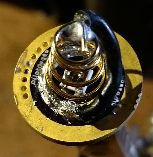
This isn’t exactly “good” science. I don’t understand all of the ins and outs of how this affects drivers, but we have learned quite a bit from experience. Some drivers will work just fine without any modification when the Illuminated tailcap is added. I’m sure there are some drivers that simply won’t work correctly at all after it is added. Most drivers will have issues initially (like not changing modes when the switch is pressed) but will work correctly once a bleeder resistor is added. This is a resistor placed on the driver directly between Battery+ and GND (the flashlight body) to “bleed” power past the driver to the tailcap. It can be placed in a number of different ways on the driver. The needed value is typically between 500-800ohms, but will depend on how much power your tailcap draws. If you already have a bleeder resistor and still have problems, try a bleeder with lower resistance.
Here are some pictures of the bleeder placed different ways.


.
.
In The Tailcap
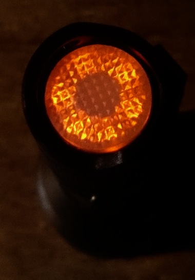
Generation 1
I highly recommend using a Gen2 design as they are much more efficient
This is where it started. In case you were wondering, the design Banggood placed in lights like the X6/X5 and the Cometa falls into this category, and is most similar to my Rev3 design. The generation 1 boards include Rev1-4 and pyro1son’s design. They consist of a single PCB on which you mount your switch (ex. Omten 1288), your resistors, and your LEDs. You then replace the typical steel retaining washer and opaque tailcap boots with translucent ones. A replacement washer can be made yourself or bought from a few places as can clear boots. See the links at the bottom of the OP.
The Rev3 design requires resistors to set your tail brightness. The needed resistance can vary anywhere from 1kohm-25kohm. The Rev4 and pyro1son’s boards introduced pads for 3x3 potentiomers to more easily adjust resistance. We recommend getting 25k or 50k rated pots to get the best range. These two versions also allow you to adjust the brightness after installation, without completely removing the whole assembly.
Gen1 boards use more power than the Gen2 boards because more light gets trapped inside the switch area.


Rev3 - Simple dual-resistor dual-LED version. LEDs and resistors are in parallel, but a trace can be cut to separate the two sides. 17mm and 20mm - Info in Post #263
Rev4 - Dual pots to adjust brightness of a dual LEDs, and a mini slide switch in the spring to adjust quickly. 16mm and 20mm - info in Post #566
pyro1son - Dual LEDs and a pot in the spring to adjust quickly. 16mm and 17mm - Info in Post #555
.
.
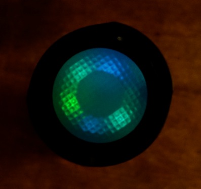
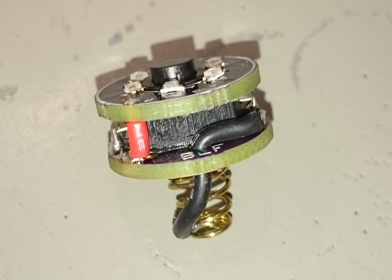
Generation 2
This includes Rev5 (and its many sub-revisions) and the still mostly-untested Rev6. They offer greatly-improved efficiency because they replace the retaining washer with a “ring” PCB, and mount the LEDs right there under the cover. This gives back most of the light we previously lost down in the switch. It also offers more room for more LEDs and color options. This ring includes pads for resistors right there with the LEDs, so you can pair it with any standard switch PCB. You could, however, pair it with a Gen1 base PCB (or the Rev5 PCB) to combine the efficiency of the Gen2 “ring” design with the easy control of the Gen1 pot/switch features. Because these are more efficient, you will probably want more resistance to get a usable brightness. I recommend 10k-30k for resistor values and 50k+ for pots.
This is the type you must use if you want to install in an S2+ with the metal switch. However, that switch design blocks much more light than a rubber cap, so be prepared for much higher power draw than in other lights.
Rev6 is the version that has an Attiny13 mounted in the tail, but as I said it is mostly untested.


Update: In addition to my own designs below, now there are options available made by Led4power and/or Lexel
Rev5 - This is a base PCB to give more function to the “ring” type PCBs. It is very similar to Rev4 but with wire connection pads instead of LED pads. 16mm - Info in Post #691
Rev5.1 - Supports six LEDs on three channels, each with their own resistor. Can be used with any switch PCB or paired with Rev5 or pyro’s PCB for more control. 16.5mm - Info in Post #746
BIG SWITCH - This is identical to Rev5.1, but larger overall to work with larger switches, like the Omten 1217 or some forward-clicky switches. The center hole is 8.4mm diameter, and all bottom pads should clear a 12mmx12mm switch body. 19mm - Info in Post #1064
Rev5.2 - Supports six LEDs on two channels, each with their own pot mounted on the ring. Can be used with any switch PCB or paired with Rev5 or pyro’s PCB for more control. The two channels can be merged or the pots bypassed with jumpers. 16.5mm and 18mm - Info in Post #1050
Rev5.3 - Set of both Top and Bottom boards. Top supports six LEDs on two channels, each with their own balancing resistor that can be paralleled or bypassed. Connects to the Bottom board with standard 0.025” header pins through matching vias. Bottom is similar to Rev5, supports dual pots and mini slide switch. 16.75mm Top and 16mm Bottom - Info in Post #1184
Rev5.3 Pot - This is an alternative to Rev5.3 Bottom. It is similar to Pyro’s board, with a single pot in the middle of the spring. It also connects to Rev5.3 Top with header pins. 16mm - Info in Post#1256
Rev6 - Untested “smart” ring design with MCU and six LEDs all in one package. 19mm - Info in Post #729 and #743
Note: Rev5-6 are designed around the dimensions of the Omten 1288 and probably won’t fit on anything bigger.
LINKS
These links may be where I bought mine from, or just a good example to show you what you are looking for. In any case, most of these items can be found from many sources all over the internet.
Omten 1288 switches: MtnElectronics , Kaidomain
Translucent Spacer (5/16 Nylon washer) at Home Depot
Various Switch Covers/Boots from Kaidomain
16mm Clear Switch Cover/Boot from Simon
Lighthouse LEDs
Cheap resistor pack from Fasttech
50kohm range 3x3 potentiometers on ebay
Small slide switches for Rev4, 5, and 5.3 boards on ebay

