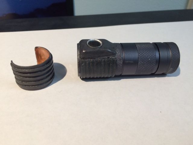
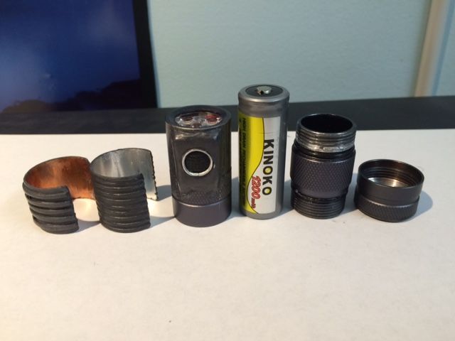
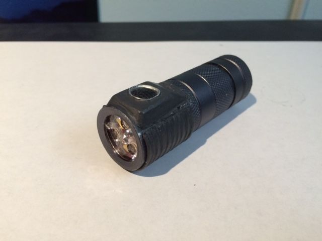
[Mod] Convoy S2+ Mini - triple XPL with sideswitch *opinions needed*

Awhile back I modded a Convoy S2+ mini to a triple. In doing this mod, I also expanded the interior of the battery compartment so that it fit 18500 cells with no changes to the exterior of the light other than the triple emitter. Here’s how I did it:

The stock pill is quite long and has a lot of empty space in it especially with a relatively flat driver inside. Rather than have all this empty air, I decided to shorten the pill so that the driver sits much closer to the emitter shelf. I could have instead installed a copper heatsink, but for this mod I wanted to see just how much power I could get into a small light.

Converting this light into a triple and running 18500 isn’t hard. The key to this mod are the adjustments to the pill. I did this with just handfiles, a variable speed power drill (no drill press), a cylindrical cutting bit with a smooth bottom, a vise, and some scraps of aluminum. Here are the steps:

  • STEP 1: FLATTEN the top of the pill. The pill has a rim around the top edge designed to keep a 16mm star centered. That rim needs to be filed off in order to make room for the 20mm triple star. 20 minutes with a large handfile takes care of this.
  • STEP 2: REMOVE the top portion of the pill threads. The top of the inside of the head isn’t threaded where the reflector was. This was fine with the stock aluminum single-emitter reflector, but a Carclo triple TIR optic isn’t as tall. If you mount the triple star and then Carloc optic and screw it in, it won’t set fully to the top of the light. The top portion of the pill threads will stop when they get to the unthreaded portion of the head. There are two ways to fix this: (a) use a spacer, or (b) file off the top portion of the pill threads so they no longer stop the pill from screwing into the unthreaded portion of the light. Since I was going for minimum size, I chose option (b).

I mounted the Noctigon triple star with optic on top, then screwed it into the light and took an approximate measure of the gap between the top of the optic and inside top of the head. Then I removed the pill and filed off the top portion of the pill threads to that measurement. I used a handfile with indoor stairway grip tape wrapped around the pill to protect the saved threads and make it easier to hold while filing.

  • STEP 3: SHORTEN the back of the pill. Just file it down with large handfile. Or if you want to save some time, saw off part of the back with a hacksaw and then file it flat. Don’t worry about saving the little shelf for the driver… the plan is to make a new one. File a couple notches into opposite edges of the bottom of the pill so you’ll have a place to insert needle nose pliers when screwing it into the head.
  • STEP 4: CUT a new driver shelf. I put the pill upside down in a large vise. Then I took a small scrap of aluminum sheet and bent it into a “U” shape with a flat bottom. The length of the legs of the “U” were about the height of the inside of the driver + a little extra for the driver wires. I then inserted this scrap into the bottom of the driver with the flat bottom of the “U” facing up. The purpose of this little scrap of aluminum was to keep the cutting bit at approximately the same height from the top of the driver.

Once this was in place, I put the cylindrical cutting bit in the drill and cut a new shelf for the driver. This only took a few minutes. It’s rough and not perfectly flat, but that’s ok… it doesn’t need to be perfect. It just needs to provide a base for the driver. Make sure to use a bit that has a FLAT smooth bottom with cutting edges on the sides only.

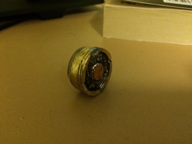
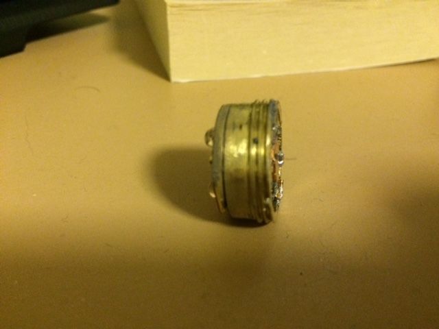
  • STEP 5: ASSEMBLE the pill. Install the Noctigon triple emitter and wire it to the driver. Insert the driver and solder it to the pill. I placed tiny copper scraps in the solder joins between the driver and pill to help bridge the gap. I also removed the BLF17DD’s rather long driver spring and replaced it with a copper disk. Since I wanted max power I went with a domed triple XPL (originally 3C tint, but later changed to 3D tint) with widened Carclo 10507 optic. The driver is a BLF17DD FET driver.
  • STEP 6: TAILCAP. I found I hadn’t quite shortened the pill enough for the light to fully close with a Kinoko IMR 18500 inside. I could have removed the pill and filed it down a little more. But rather than do that I decided to slightly modify the tailcap. A little filing to the baseplate below the rubber button, and a slight extra extra turn to the brass retaining ring were all that was needed to give me that last 1 mm. While at it, I also solder-braided the tailcap spring with 22-gauge wire.

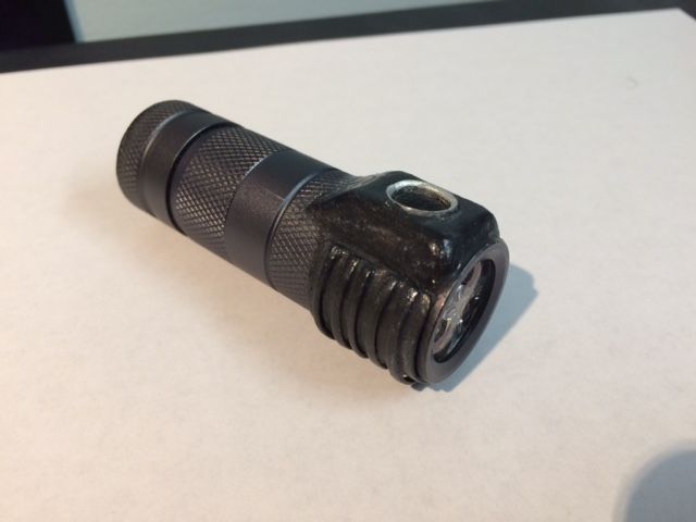
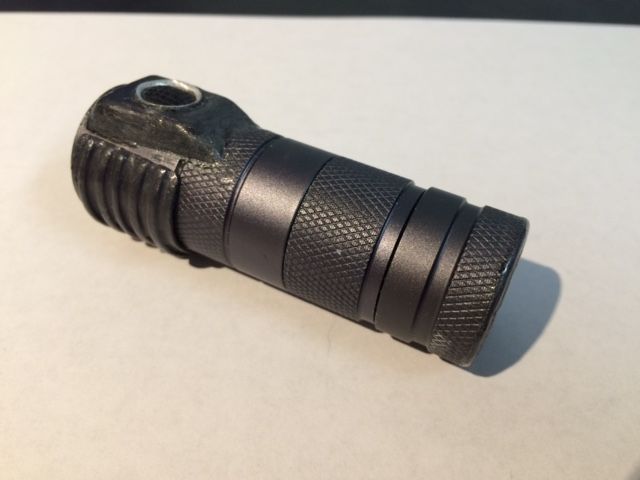
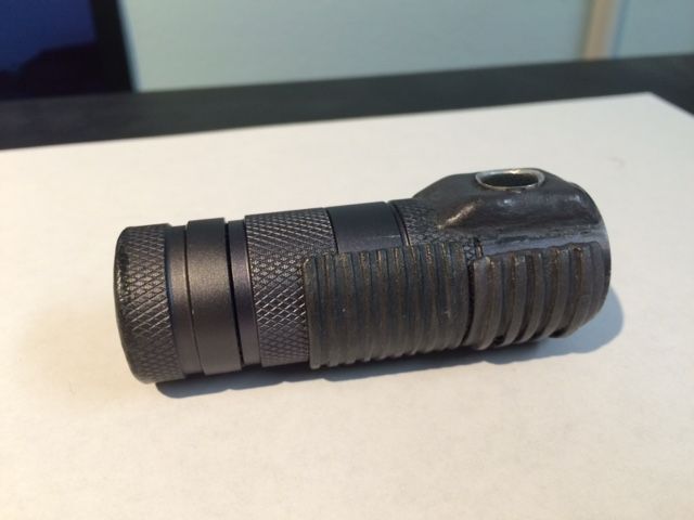
Here are some pictures of the completed pill (apologies for the fuzzy iphone pics):
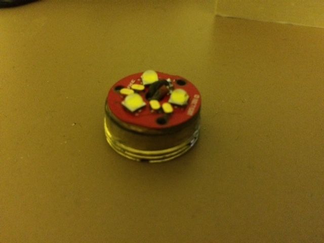

This light puts out a wall of light in a tiny package. Output at turn-on with a fresh IMR cell should be around 2500 lumens. Impressive in a tiny 84mm long pocket light. It gets hot really really fast. If you turn it on and hold it 1 cm in front of your hand, you’ll get a burning sensation in your hand almost immediately just from the emitted light (and your other hand will shortly get a burning sensation from the heat in the head). I figure an appropriate turbo timer is probably 30 seconds.
………

EXTERNAL SIDESWITCH MOD IN PROGRESS
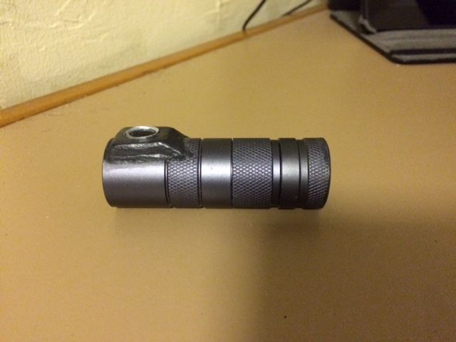
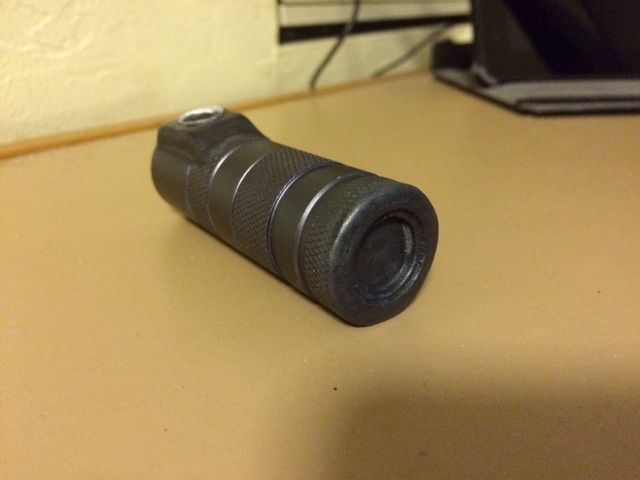
Of course I didn’t leave well enough alone and am still tinkering with this light. I replaced with the BLF17DD driver with a Nanjg105c modded with a FET and DrJones lumodrv electronic switch firmware. I drilled a small hole through the side of the head for the switch wire. This is soldered directly to one leg of a tiny tact switch. The other leg of the switch is bent down into a small depression drilled into the head and soldered in place with conductive silver epoxy. I tested it and it works! This is now a side-switch light! Here’s a picture of the work in progress:
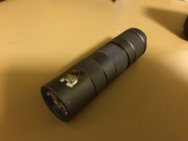
Still to do:

  • The switch is done, but it now needs a protective enclosure and rubber switch boot. This should be fairly easy to make with sheet aluminum and cutting down a standard switchboot. I have some ideas on how to do this switch. I’ll probably add a rim around the button to help protect it and make accidental pocket activation less likely (accidental pocket activation at 100% power would be BAD with this light).
  • I might add a sliding cover over the switch button. Thinking of something that slightly locks in place but can be slid down with the thumb revealing the button. Not sure if I’ll do this, but would help protect against pocket activation while still letting the light be activated relatively easily.
  • Tailcap mods. Once the sideswitch is done, the tailcap switch should no longer be needed. I plan to saw most of the tailcap off and replace it with a flat contact plate with a spring in the center. This should allow me to shorten the light by about 1 cm without affecting performance or battery capacity.

I’m also thinking about modifying a second tailcap by removing the switch and then mounting the backplate at the very bottom of the cap without shortening the cap. The goal would be to make a tailcap that lets me run the light on 18650. I think I can do this without making the light longer than than 86mm or so.

Nice. Good job.

Regards

Nice! Modding to the max! I have been through numerous battery space problems and solutions, but this is all my solutions at the same time plus a few more :-)

A small one of these might be in order!

Very cool!

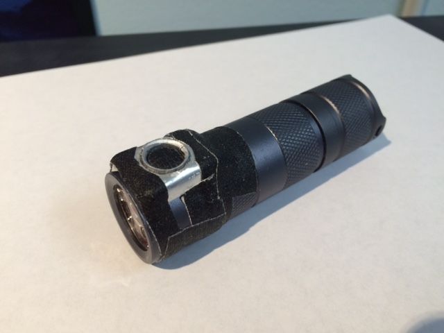
Here’s a pic with my first attempt at a switch cover (the tape is temporary to allow me to check the fit and switch tension):

The cover itself is made out of 0.032” aluminum sheet cut and bent into place. The raised ring around the button is a strip of the same sheet glued into place with super-glue. The button is a standard switch button cut and trimmed to fit.

I decided to go with a small recessed switch button as a safety measure. Since this light gets VERY hot at max power and since I wish to remove the tailcap switch, I want to minimize the chance of accidental pocket activation. The button itself is also relatively stiff. Even then, if I EDC this, I’d likely leave the light at low power when not on to minimize risk of accident. As-is, I’d rate this switch as being less likely to accidentally turn on in the pocket than any of my stock side-switch lights, including the Zebralight SC52.

Once I’m satisfied I’ll do the final finishing touches to the switch:

  • Remove the tape and glue the switch plate into place with arctic alumina.
  • Fill in all cracks at the edges of the switch plate with arctic alumina or green stuff epoxy.
  • File down the epoxy and any rough edges on the switch plate.
  • Paint the switch paint to match the body anodizing as close as possible. It won’t look as good as the anodizing, but should look close enough to roughly match.

Once that is complete then I’ll work on couple tailcaps:

  • Short tailcap - remove the switch and saw off most of the cap, add a copper backplate and spring, paint to match. Should shorten the entire light by at least 1 cm, while still allowing the light to fit 18500.
  • 18650 tailcap - remove the switch while slightly lengthening the tailcap. Add baseplate and spring. This one will be harder to do since glue alone won’t hold against the spring pressure. Goal will be to make a tailcap that allows the light to run on 18650 in as small a package as possible.

I often tinker with my lights even when they are “complete”. I wouldn’t be surprised if even after I complete all the above I make and try out alternate switch covers or other things.

Nice work, a few thoughts:

You could have used the pill from a S2 it is way shorter than the S2+ pill. Then make the top of the pill where the led goes flat and solder the noctigon directly to the pill.

Have you seen this thread? There the side switch is really discret.

Daggum! That is AWESOME!

A ton of work on that pill for sure…and with the extra mAh of the 18500 it probably won’t come on…blind everyone in front of you, then run out of battery :stuck_out_tongue:

Great build…keep up the great work!!!

I thought about doing the switch that way with an internally mounted tact-switch and a piston, but it would have made the light longer. One of the things I was trying to do was make it as short as possible… and the only way to do that was an external switch.

Did a bit more work on this light. Here are some updated pictures:

Switch cover and boot installed and painted and the tailcap switch removed:

I glued the cover on with arctic alumina. One disadvantage is if I want to remove the pill I’ll probably need to cut the epoxy and remove the cover so I can access the solder join on the tact switch. I think if I do that I should make a little plug for the switch wire to insert into. A plug would make pill access easy… I’d just need a tweezers or needle-nosed pliers to pull the wire out of the plug before unscrewing the pill.

Rear of the light showing the modified tailcap:

After removing the tailcap guts, I used a hacksaw to saw off everything behind the switch retaining ring. I left the brass switch retaining ring in and used it to brace a round copper end plate. The copper plate has a raised tab on the inside for negative battery contact. I glued the contact plate and retaining ring into place with superglue and then painted it.

I didn’t even realize I’d done it at first, but this light actually has no battery compartment springs at all. There’s a raised copper contact at each end. Battery contact is maintained just from screwing in the battery tube to the head. It feels very secure and makes a good connection so I think I’ll leave it as-is. This also allows the light to be super-short…. the entire light is just 72mm long!

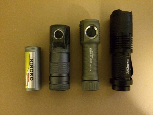
A picture of the modified light showing its size.

Left to right: Kinoko IMR 18500 cell used by the modified S2+ mini, the S2+ mini, Zebralight SC52w, Sipik 68.

Here’s a picture with a heatsink installed.

I made a removable heatsink out of some copper sheet with soldered on copper strips and kester solder paste. In addition to absorbing and radiating heat, it isolates the hand so fingers aren’t so close to the pill. The heatsink allows for much longer runtime at max power. The downside is it makes the light heavier and doesn’t look as pretty.

You can also see from this picture that my paintjob on the heatsink and switch doesn’t quite match the anodizing. I may try going back and repainting it to see if I can get it closer. I think the paintjob on the tailcap is a closer match. When I painted this I manually blended acrylic water-based hobby paints, then brushed it. To provide a durable finish I applied a layer of brush-on super glue, then lightly sanded the glue with steel wool to reduce the gloss.

Still to do:

  • Make alternate 1x8650 sized tailcap.
  • repaint switch cover and heatsink to try for closer match to body anodizing.
  • consider reducing the height of the switch cover. As-is, the cover stands up fairly high from the light. It would look more graceful if it were flatter. Also after having used it a bit, I don’t think it needs to be raised quite so much around the button. I estimate filing down the bottom of the switch cover could reduce the height of the cover by 2mm.
  • consider making and installing an internal socket for the switch wire to make future driver and emitter swaps much easier.

I flattened the switch plate a couple mm. Here’s a picture:

This change made the switch around 2mm flatter so it doesn’t break up the line of the cylinder so much. The button is also less recessed and easier to press. Risk of accidental activation is higher, but it’s still a relatively stiff button.

I’m not happy with my paint job on the switch plate and heatsink. It’s durable, but it looks homemade. My paint methods work fine for painting something black. They even work ok for matching grey duracoat. But matching the beautiful metallic grey anodizing on the S2+ mini seems impossible.

I wonder if maybe I should just go with the polished metal look: remove the anodizing with greased lightning and sand off my paint job, then polish up the bare metal. I’d still probably need to use a little silver paint to hide the arctic alumina (or maybe replace the out layer of it with silver-colored epoxy), but that would be about it.

Looks a bit kludgey (as you stated) but I think you just created a homemade 18500 zebralight. That is pretty cool.

Agreed it really does look a lot like a Zebralight with the grey color, raised button housing and heatsink fins. It’s shorter and fatter than my SC52, but noticeably heavier due to the copper heatsink and larger battery.

It’s also ridiculously overpowered for such a tiny light. Without the heatsink on a fresh cell I figure I can run it for 10 seconds at max power before it gets too hot to touch under the head. With the heatsink I can probably go 30 seconds. Or perhaps a minute if I play “hot potato” with it and swap it back and forth from hand to hand.

Even at 25% power it’s noticeably brighter than my Zebralight SC62w at max power. It can be run continuously at 25%, but still requires “hot potato” especially when the heatsink is off. It’s a good thing I’m using a ramping driver with lots of steps (Dr Jones lumodrv with FET).

Here are some updated pictures:

Light with 2 external heatsinks added:

The larger heatsink at the front is made of copper with soldered on copper strips. The thinner one at the back is a single piece of aluminum sheet with slots filed in.

With both heatsinks installed the light is substantially heavier, but can be run at max power for much longer. I painted the heatsinks to try to match the anodizing. The paint significantly cuts down on heat conduction into the hand holding the light, but perhaps that’s a good thing as it allows the light to be used at max power much longer without getting too hot to hold.

Here’s a pic with just the thinner heatsink installed:

The thin heatsink is enough to absorb some heat from the head allowing the light to be run longer at max power, but not as much as the copper heatsink or the combo of both heatsinks. I think it looks better though. The ridges in either heatsink also help provide some grip.

Here’s a picture of the disassembled light:

I quite like how it came out. The paint job isn’t a perfect match to the anodizing, but it’s fairly close. Not really noticeable except on close inspection. As a pocket rocket this thing wows everyone who sees it. 2500 lumens from a light shorter than a Zebralight SC52. It’s my current EDC. :smiley: :bigsmile:

I think this light is mostly done. I’m not sure I’ll do anything else to it, but I’m considering the following additional mods:

  • File down the switch cover a bit more to try to make it a little smoother, but I’m not sure it’s worth the effort. The paint job on the cover is a very close match and I’m not sure I could get it so close on a second try.
  • Mod a second tailcap to allow the light to take 18650s, but that’s rather low priority at this point since 18500 is much shorter, lighter and more pocket friendly. And I don’t need the extra capacity.
  • Make a single piece heatsink sleeve out of copper with copper ribs that slides in from the back and covers the entire body tube and head (except for the switch). This would make the light slightly fatter and a lot heavier, but would allow even more prolonged use at max power. If I make it all of copper and put a matching copper ring around the tailcap the light could look quite pretty.

I filed down the switch cover an aluminum heatsink a little and repainted it. This is about the best I can do with the paints available.

The paint job on the switch and heatsink still just doesn’t match the anodizing on the body tube. The color is close, but the texture is off.

I’ve concluded that it’s pretty much impossible for me to get a perfect match with the anodizing with the paints I have available.

It looks ok from a distance, but still looks homemade close up. I have a few options at this point:

  • Option 1 - Leave as-is. It looks decent even if not great.
  • Option 2 - Paint the body tube in grey to match the paint on the head. It wouldn’t look great, but at least it would be uniform.
  • Option 3 - Paint the entire light black. The black is much easier to do well since I don’t need to blend any paints to match color. Also any imperfections in the texture are hard to see. From experience, the black paint just looks like shiny anodize.
  • Option 4 - Strip off all paint and anodizing and then polish up the bare metal. This is the most work-intensive option.

I’d have to disassemble the entire light to remove the anodizing, including removing the switch and switch cover, which are currently epoxied on. Then I’d have to soak the anodized parts in Greased Lightning to remove the anodize.

Removing the paint is also high effort. Every bit of it would need to be manually scraped and filed off. And it clings really well because of the layer of super-glue brushed on top as a finish. (Or I guess I could try soaking it in glue remover)

The light might look quite decent with bare metal. the switch cover body tube and heatsink are aluminum. The tailcap would have visible brass, copper and aluminum. I could use the other heatsink which is copper for more contrast. The only thing that would look a little off is the arctic alumina holding on the switch plate. I could replace that with shiny silver epoxy, but it still would never look as shiny as bare metal.

A second potential disadvantage is that without the layer of paint there might be to much heat conduction from the head into the hand holding it. This might further limit runtime on max power.

Anyone have an opinion?

Do you have any beamshots so we can see this thing punch a hole in the side of your garage like a Type X Phaser?

In my honest opinion,don’t try to hide your mods.Keep the original body as it is.Work with the small details like how the switch cover meets the heatsink and make the mods more visible with color of your choice (mine is aluminum).Enjoy your new “muscle flashlight” :wink:

S2+ originally has only sharp corners,I wonder if the switch cover would look more uniform if it had slightly sharper corners ?

My vote on option 1 - Leave as is: Has the look of a crack-pipe, but cool as f*ck

Awesome mod, love it! CNQG has really small switch covers and you can tint JB weld or clear epoxy to black with ordinary liquid shoe polish. I wish I were retired and had the time to do this more but it’s great to see what others come up with. Kuddo’s!

Very nice work, thanks for sharing. I look forward for the S2+ Ti version.