Lindy 4 port usb High power travel charger
Official specifications:
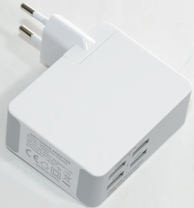
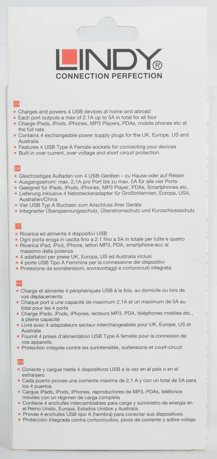
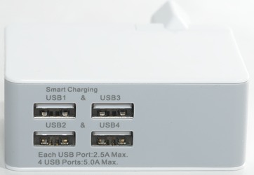
- 4 x USB Type A Ports
- Output per port: 2.5A Max
- Total output: 5A (max)
- Over Current, over voltage and short circuit protection
- Includes adapters for use in UK, Europe, USA and Australia
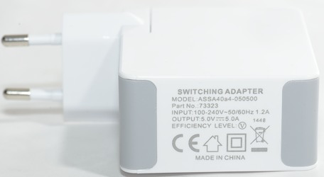
- Model number: 73323
- Input power: 100-240V 50/60Hz 1.2A
I got it from av-connection.dk
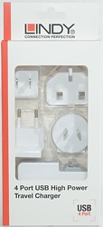
I got this charger in a cardboard box.
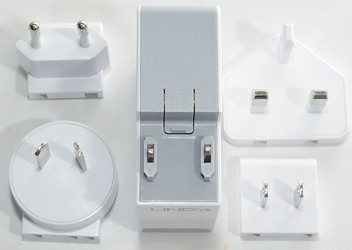
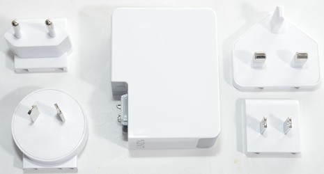
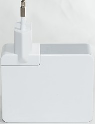
The charger has a replaceable plug and the box included four different types.
Measurements
- Unloaded power consumption is 0.16 watt
- All ports are in parallel.
- All ports has automatic coding up to Apple 2.5A
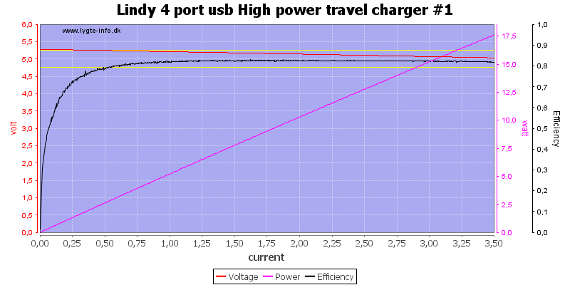
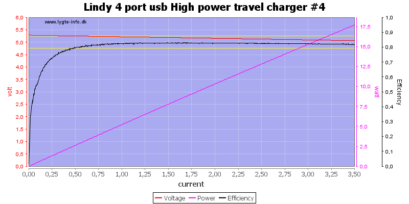
There is not much different between usb ports and no overload protection.
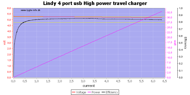
There is a total overload protection at about 6.5A.
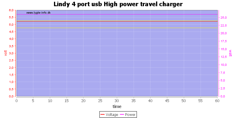
No problem running at 5A for one hour.
The temperature photos below are taken between 30 minutes and 60 minutes into the one hour test.
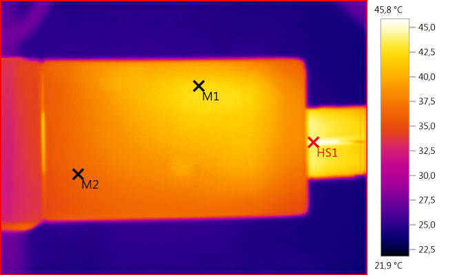
M1: 42,2°C, M2: 36,2°C, HS1: 45,8°C
M1 is above the rectifier diode.
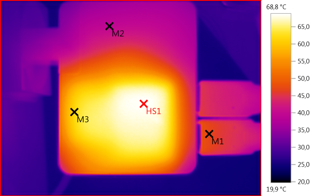
M1: 47,1°C, M2: 39,6°C, M3: 61,8°C, HS1: 68,8°C
HS1 is the mains transformer.
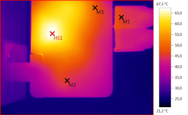
M1: 45,8°C, M2: 45,4°C, M3: 49,3°C, HS1: 67,3°C
HS1 is the mains switcher or maybe the mains switch transistor.
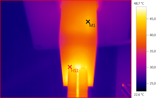
M1: 42,4°C, HS1: 48,7°C
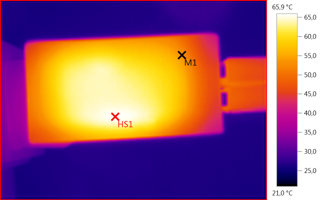
M1: 53,1°C, HS1: 65,9°C
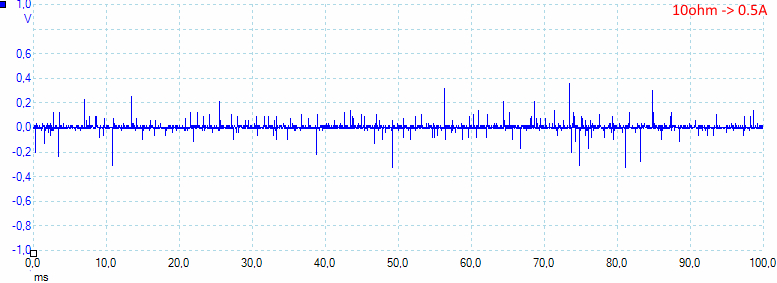
At 0.5A the noise is 30mV rms and 800mVpp, the is some peak noise.
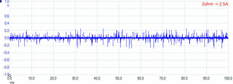
At 2.5A the noise is 31mV rms and 680mVpp
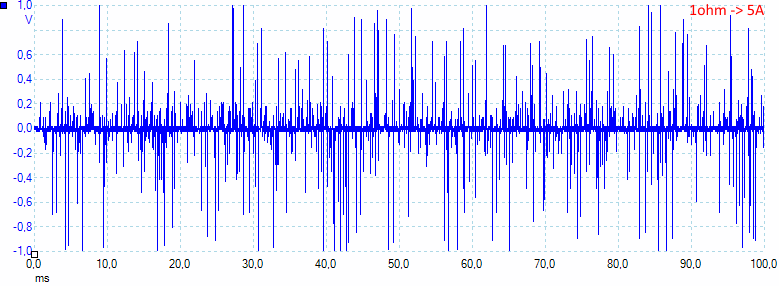
At 5A the noise is 110mV rms and 2450mVpp, at full load the noise is very bad.
Tear down
I first tried to press on it with the vice, this did not get me anywhere (I had not really expected it to). Instead I cut it open.
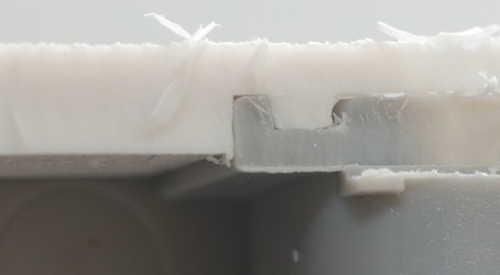
The way it was made I expected the bottom have a very solid connection to the body or the charger might break open if pressure was applied to the mains plug. As can be seen there is track in the two plastic parts to get a good connection and everything is probably filled with glue, before it is pressed together.
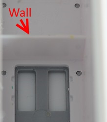
Notice the wall in the plastic, it is used to improve the isolation between mains and low volt side.
After cuttting it was fairly easy to pull apart.
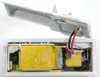
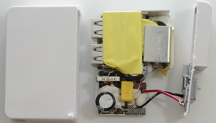
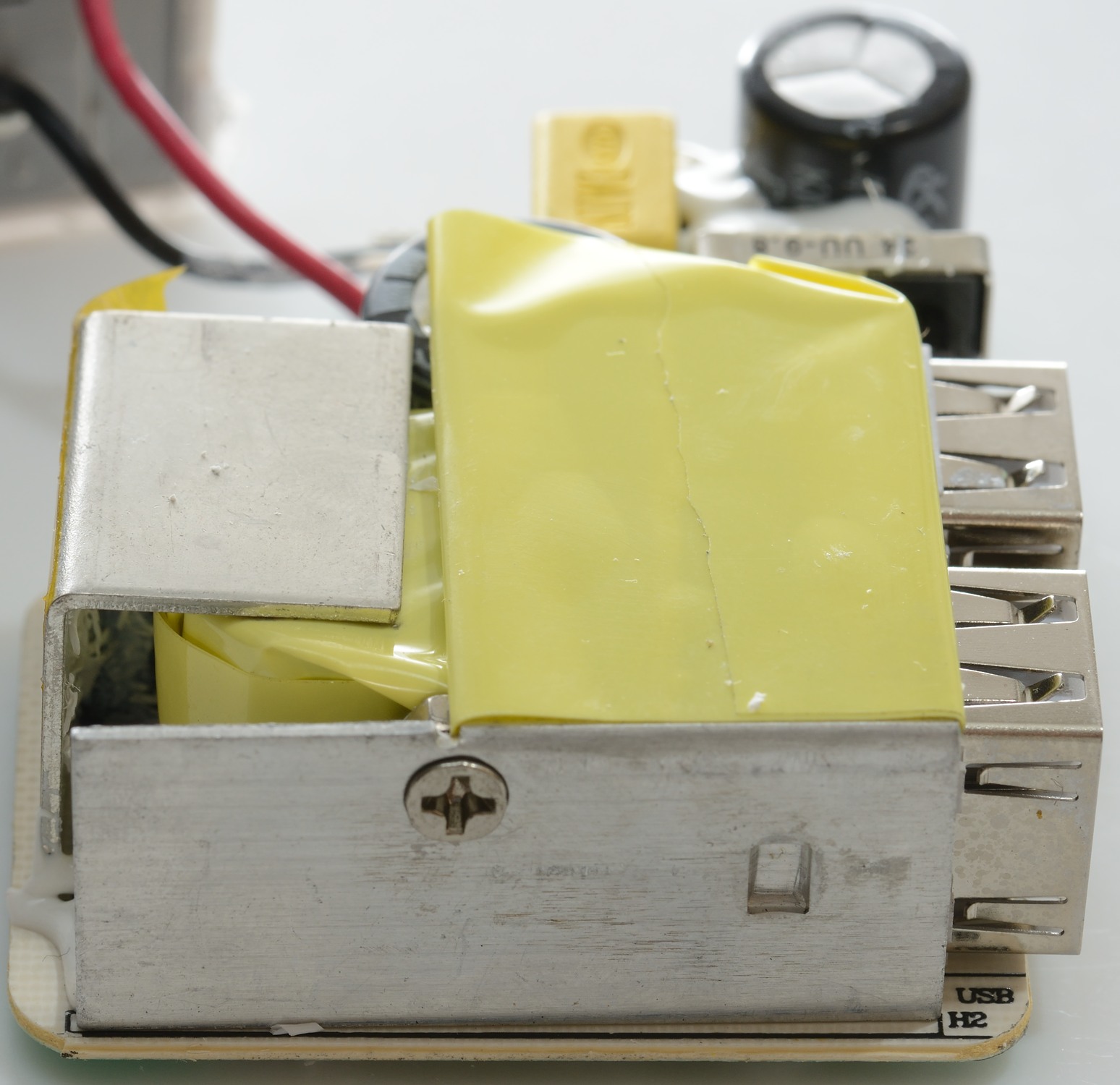
On the mains side can be seen a fuse (Brown box), a common mode coil, 4 diodes for a bridge rectifier and heatsink for the mains switch transistor.
The opto feedback can also be seen and the heatsink for the rectifier diode. The yellow tape around the heatsink is very important for isolation, because it is close to the other heatsink and the transformer.
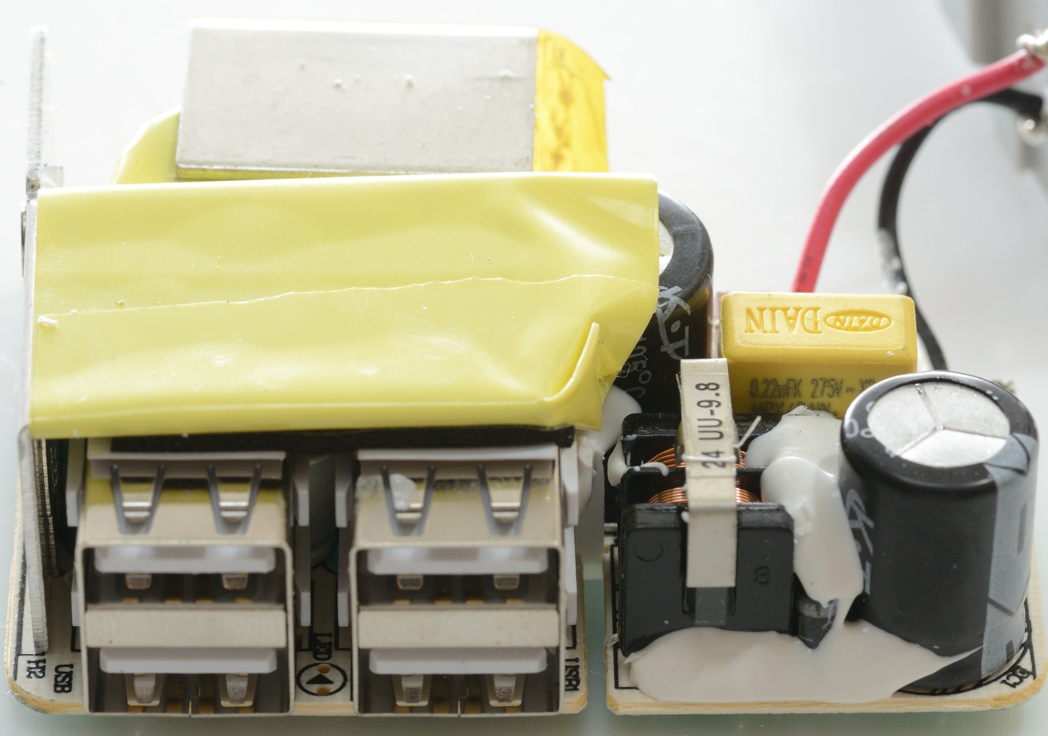
Here the four usb connectors can be seen close to the common mode coil. They are not allowed to be close and will not be it when the charger is put together. Notice the slit between them, the plastic wall will seperate them there.
One of the input rectifier diodes can be seen next to the common mode coil.
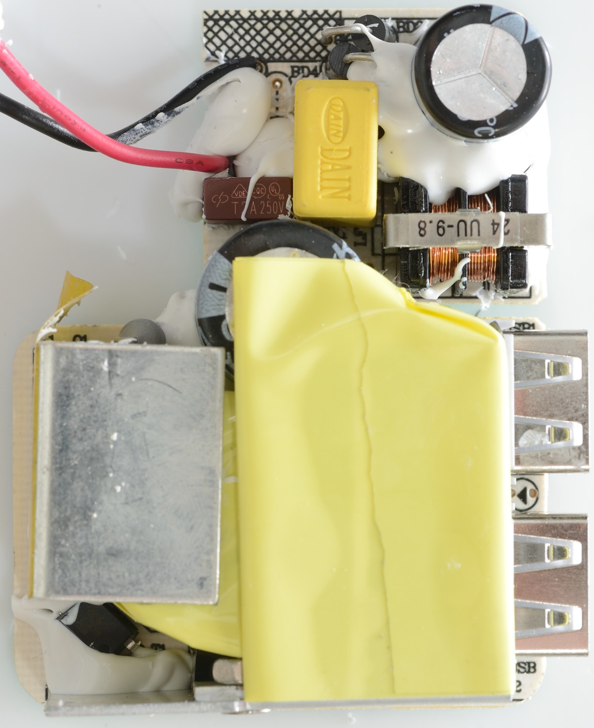
The rectifier diode heatsink on the low voltage part of the circuit.
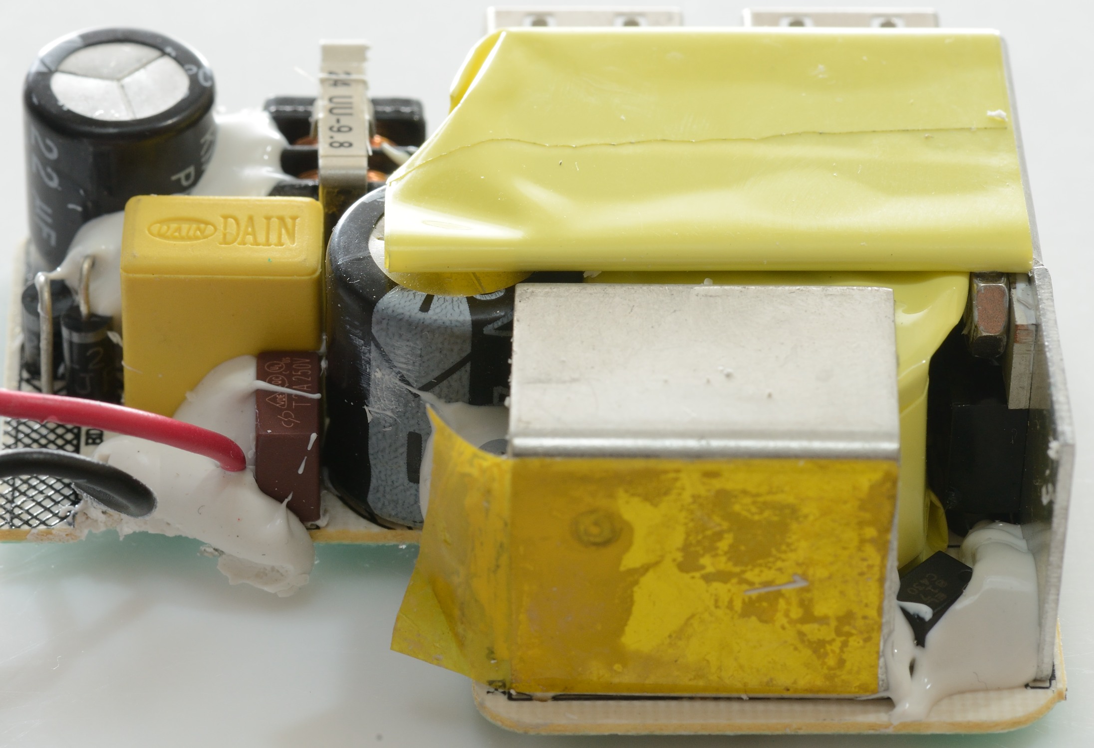
The mains switch transistor heatsink and the recitifier diode mouonted on the heat sink.
In the corner between the two heatsink is the opto coupler for feedback (It is partly hidden under the white stuff).
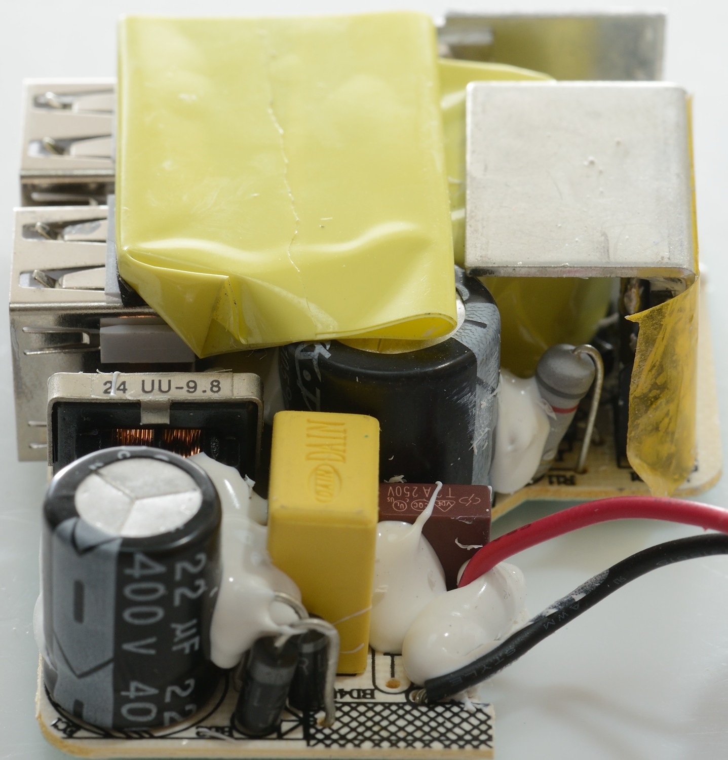
Here two more diodes of the input rectifier can be seen.
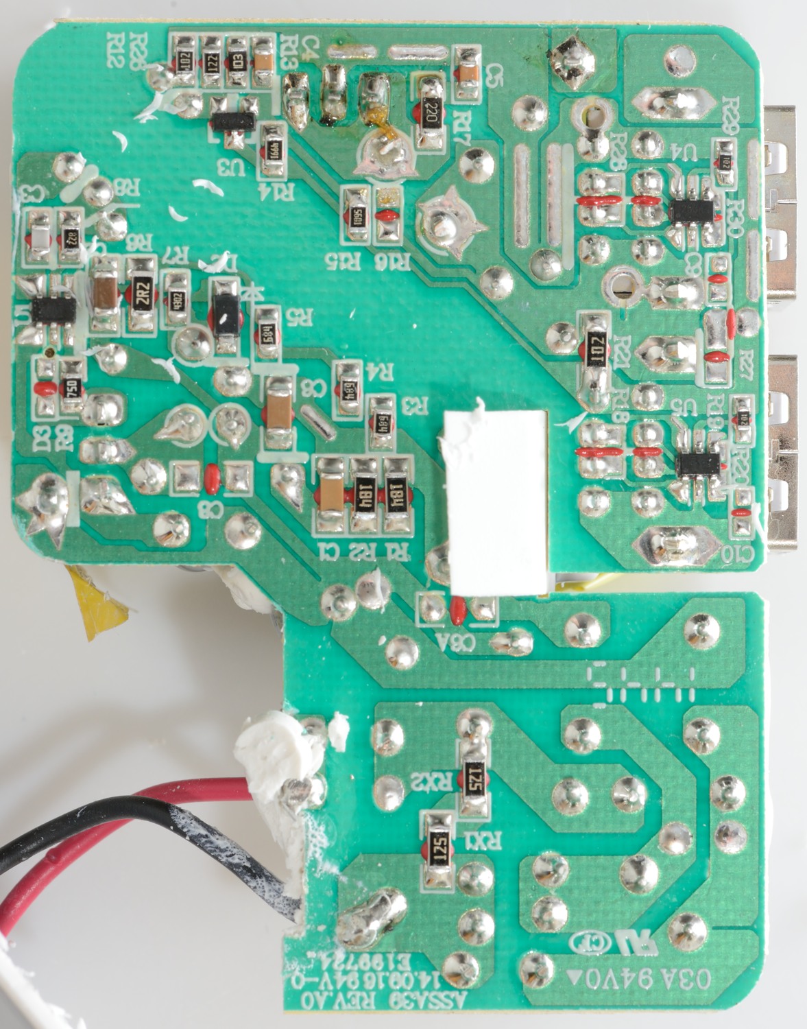
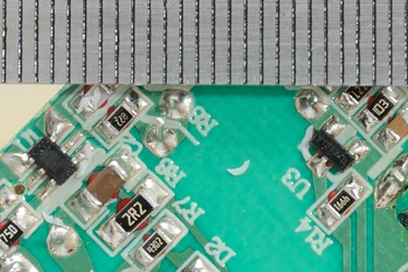
The switcher controller ic (U1) is placed below the mains switch transistor. U3 is controlling the optical feedback and U4/U5 is the automatic coding of the usb connectors.
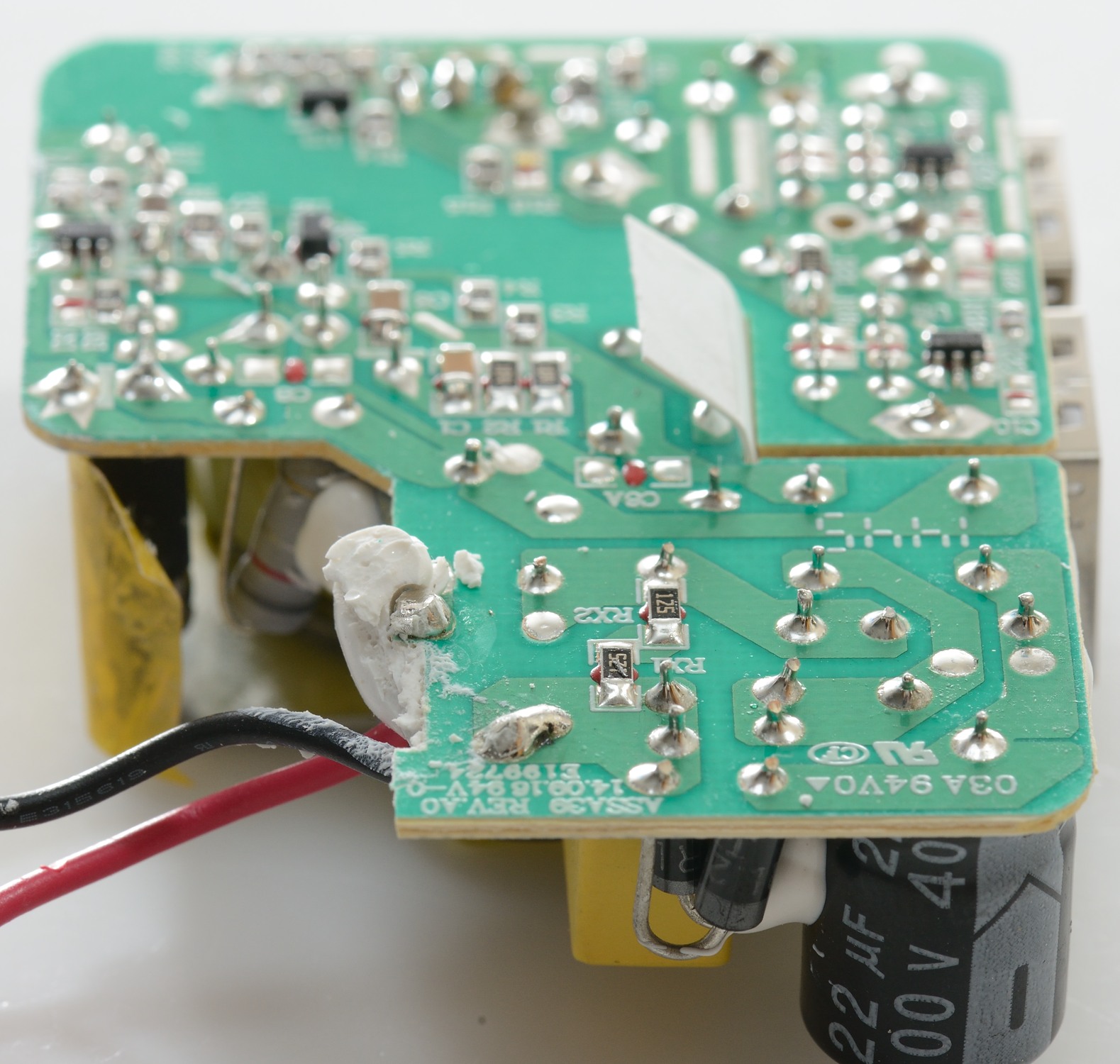
The white plastic sticking up is part of the isolation between mains and low volt side.
There is no issues with the isolation distance, it is fine.
Testing with 2500 volt and 5000 volt between mains and low volt side, did not show any safety problems.
Conclusion
The adapter can deliver the rated power and looks safe, but I would have liked over protection on each port and much lower noise when fully loaded.
Notes
Read more about how I test USB power supplies/charger