Josiah was eight years old when he began to reign, and he reigned thirty and one years in Jerusalem. And his mother's name was Jedidah, the daughter of Adaiah of Boscath.
2 And he did that which was right in the sight of the Lord, and walked in all the way of David his father, and turned not aside to the right hand or to the left.
2 Kings 22:1-2
Josiah did that which was right in the Lords Sight all the days of his life. He carried the light with him whither so ever he went, and the light reached to the far edges of his kingdom.
submitted for your approval is my entry into this years made from scratch competition. Hope you enjoy:)
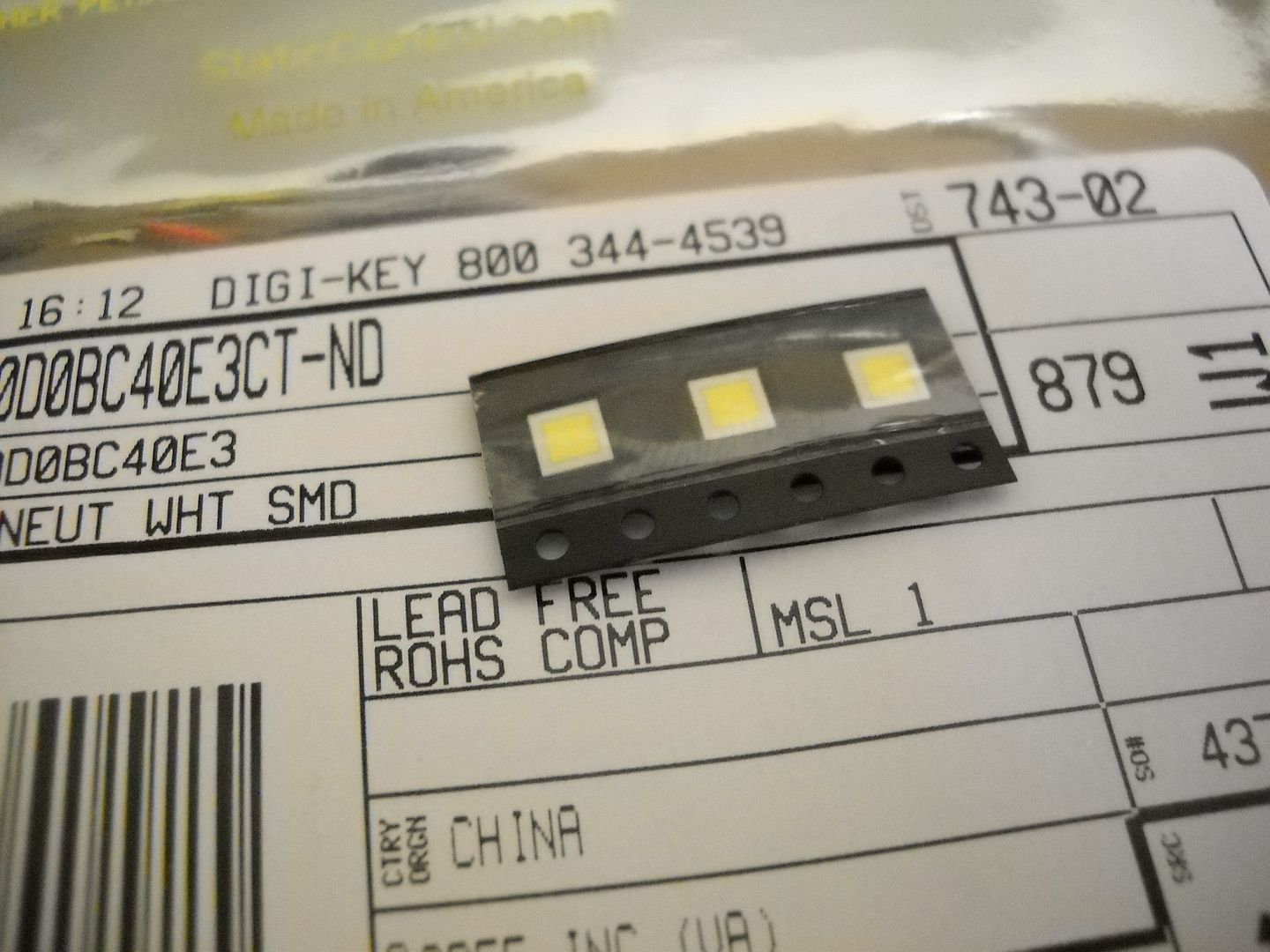
First we will need some raw materials.
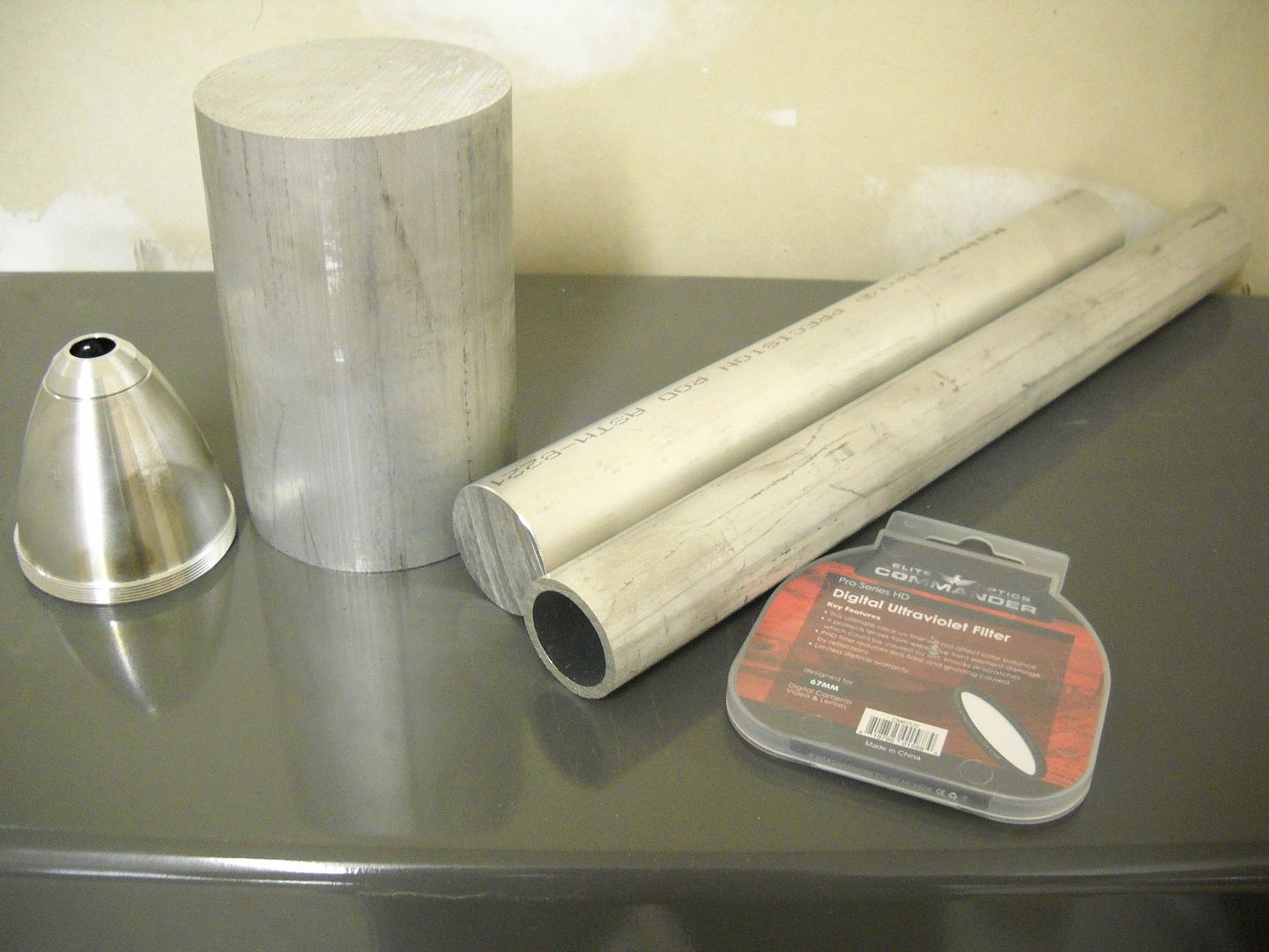
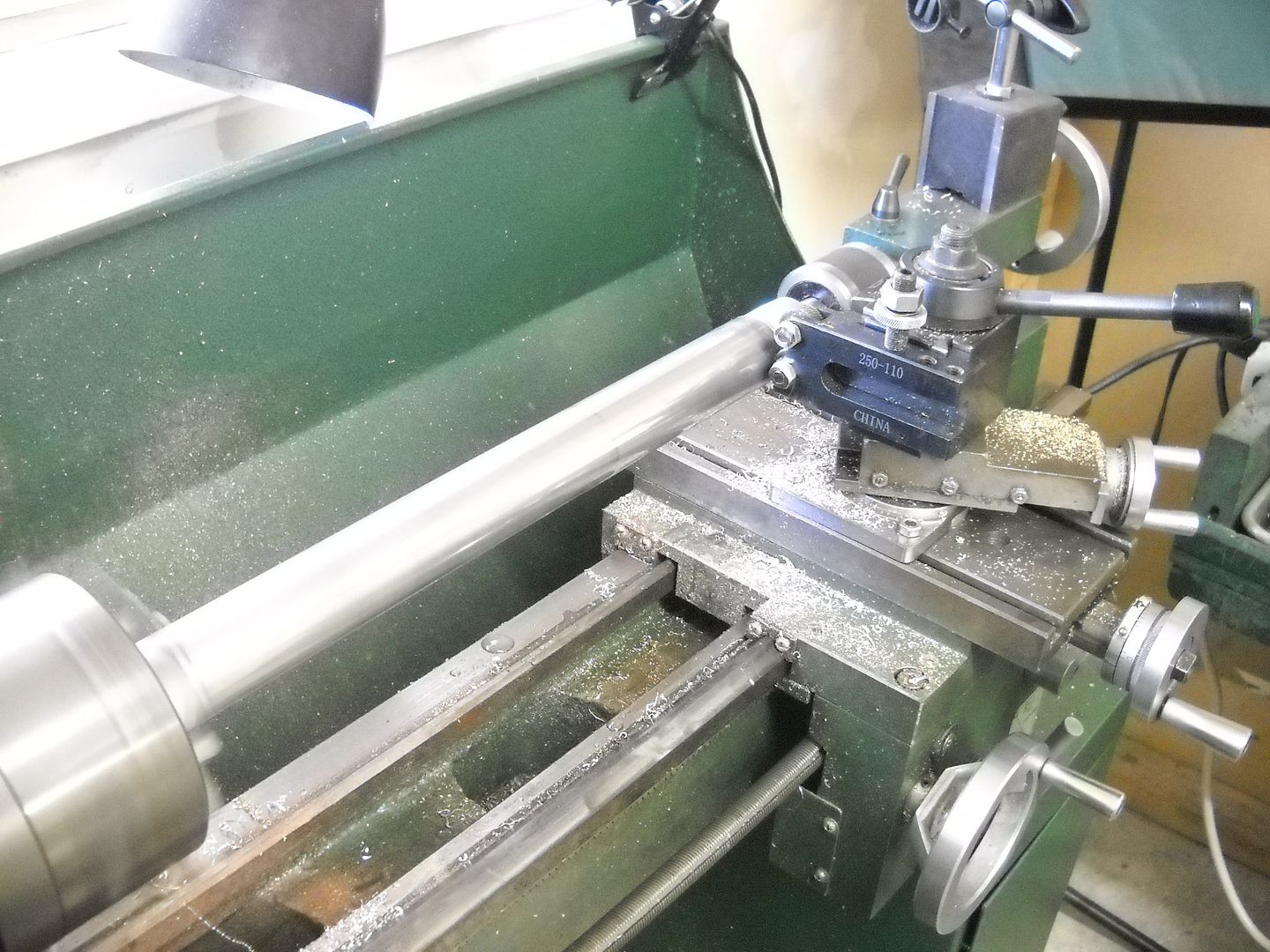
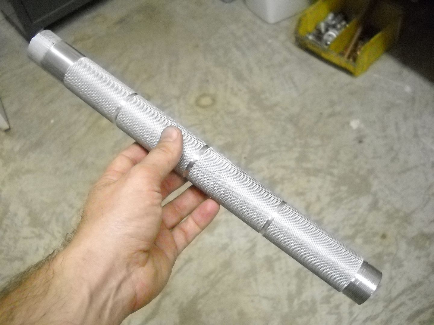
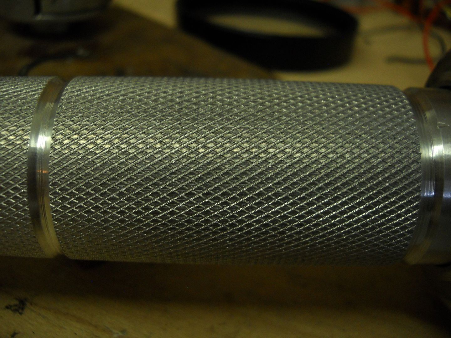
I wanted to build a long slender light this year so some SCH40 tubing is a premium choice for a body tube. Lets start there.
A little knurling and some grooves and we're all set.
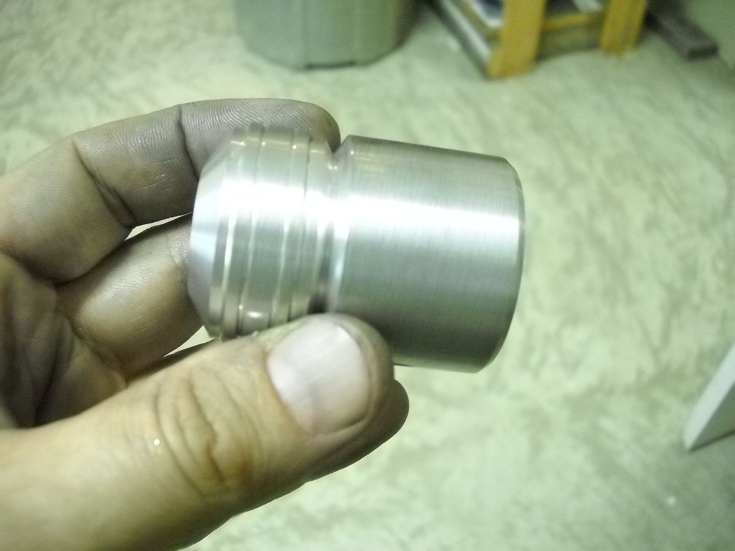
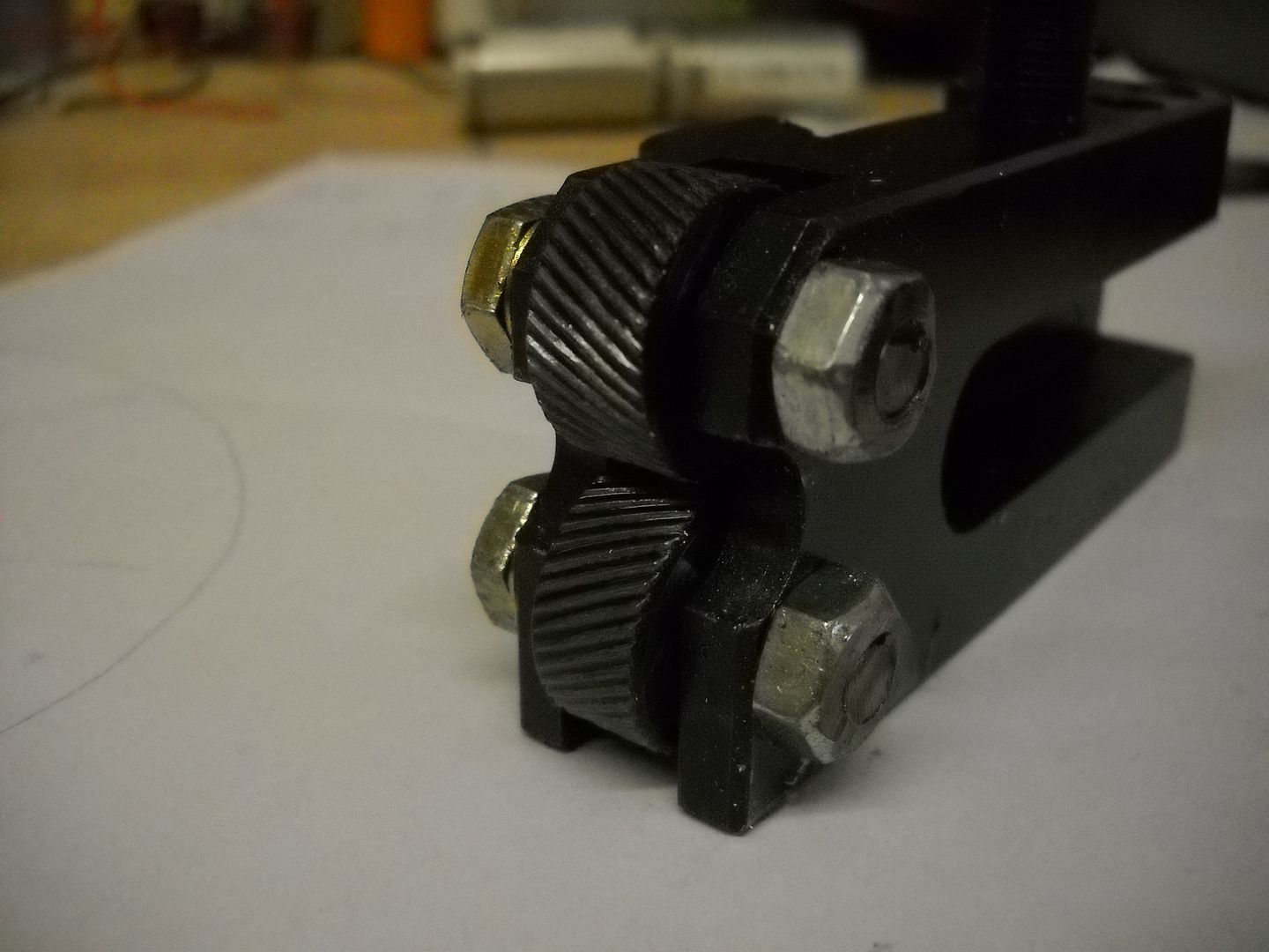
Next we'll move to the tail. I wanted to give the light kind of a scepter look.
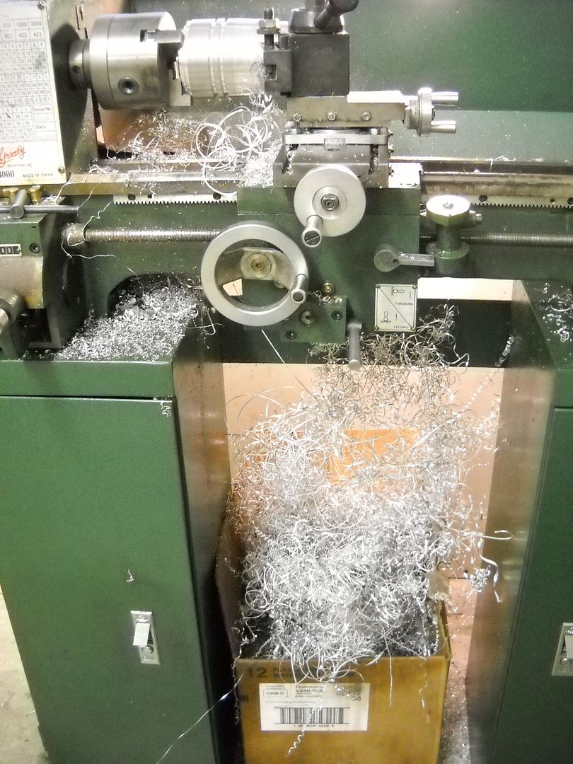
With this in hand its time to move on to the head. I have to say this is the part of the build that I looked forward to the least. Machining solid 3.250" round stock on a mini lathe is not an easy task by any means.
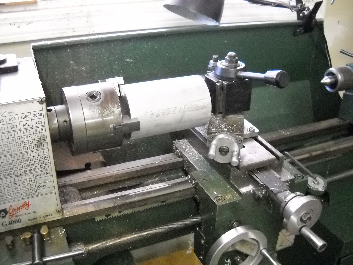
Now I am by no means complaining. I am very grateful to have my little grizz and the opportunity to build this light. But just so you have an idea, when I say a long day, I mean ya, pretty much allllll day long turning and shaping and boring and so on. Minis are versatile little creatures but not that rigid or powerful so this is a big task for one.
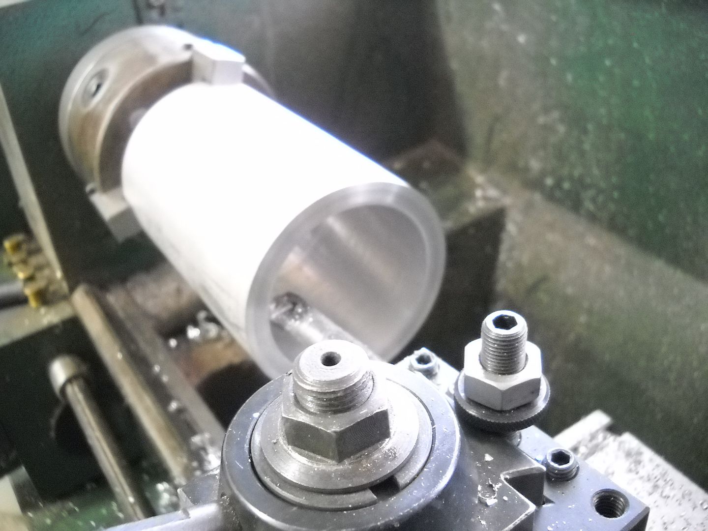
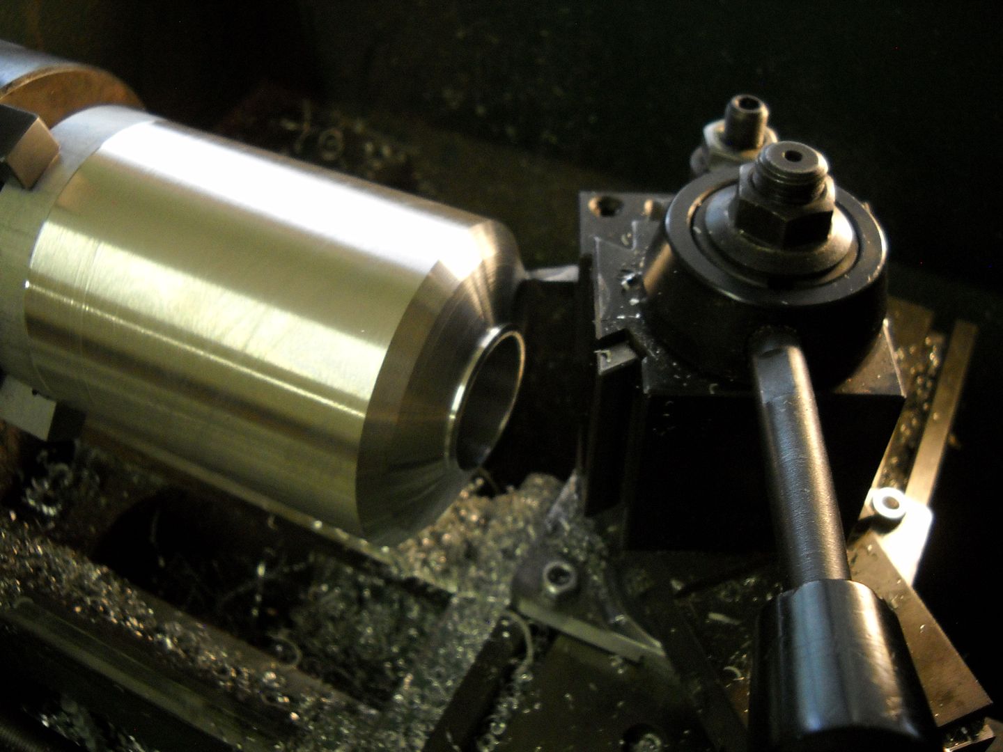
By the time its all said and done you've got more metal in the bin than left on the head. LOL
Rather than trying to thread the bezel end I just made an insert that will hold the lens and o ring in place with 4 set screws.
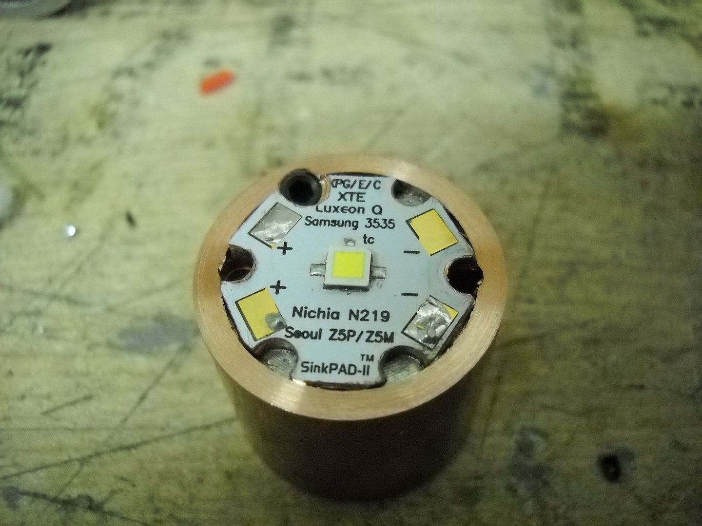
Now we can move on to the heart of the beast. The original plan was to use a de-domed XHP-70, and I did try this, but the beam was not as tight as I wanted.
Fortunately for me Cree released yet another great emitter that solved this problem. Yep none other than the XHP-35 high intensity. For those of you who have not yet seen this emitter it is similar to the other XHPs accept that the 4 dies are wired so close together there is no separation. Cree is even calling it "monolithic" Its foot print is XPG and it looks like XPL, but its 12V
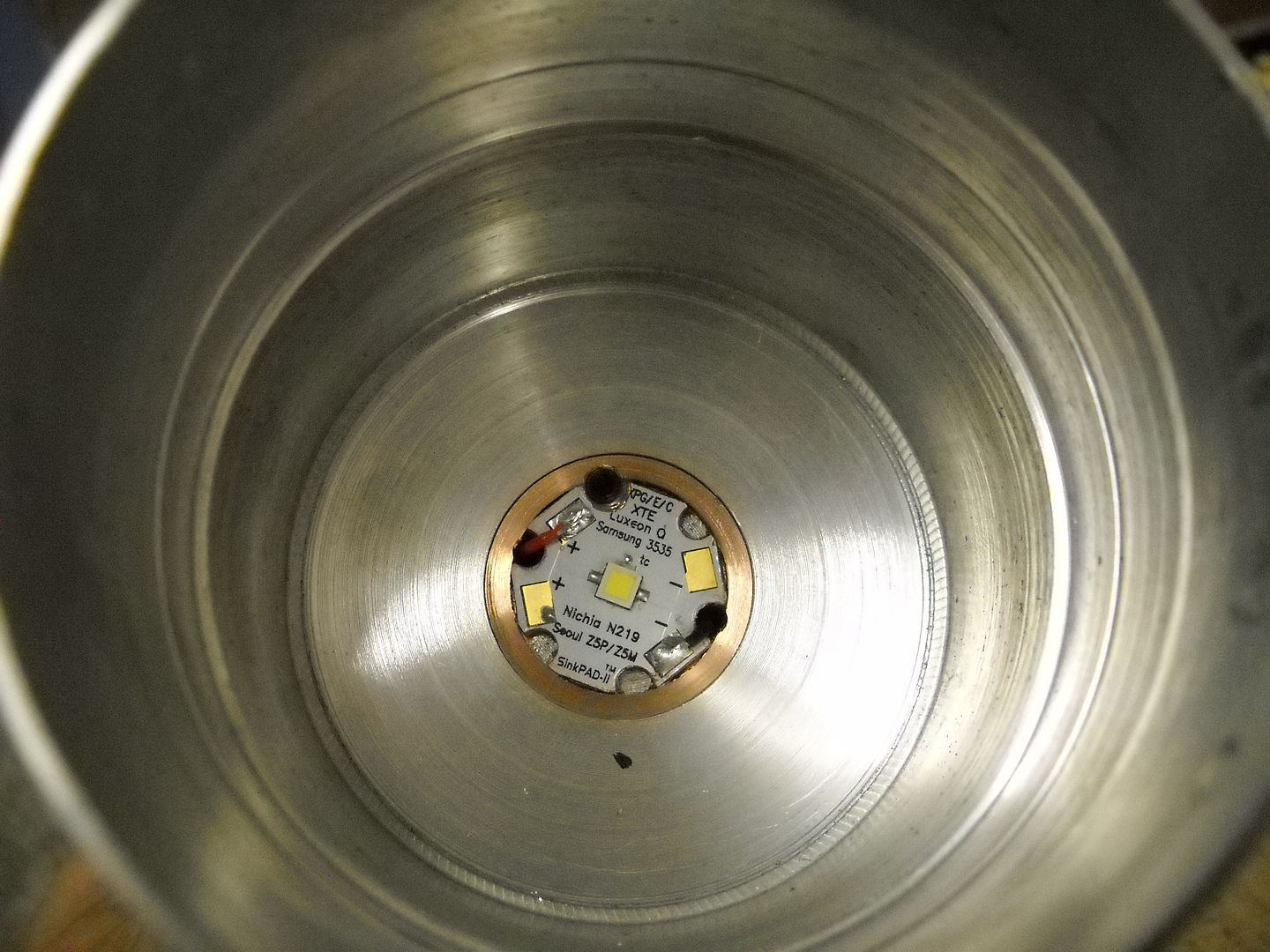
Since the head of this light is so deep it was hard to get a perfectly flat surface for the emitter to sit on. Perfectly smooth was easy, but flat not so much. I kept getting a slight hump even when taking only 2k at a pass. So I decided to just bore the center of the head and put a 1" diameter copper slug in the center. This worked out better in the end for the heat sinking anyway. I reflowed my star to the core.
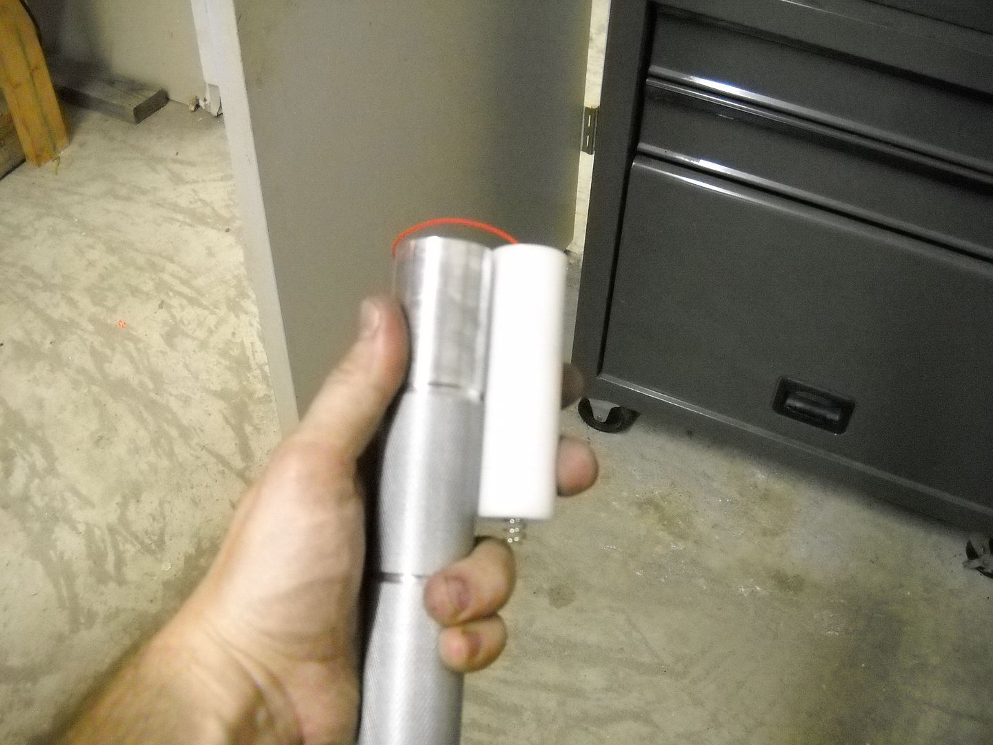
I made this body for use with 4x 26650s and like I said I wanted it long, so even with the cells a plug had to be made to fill the extra space.
Later I replaced that spring with a copper rod because with a twisty cap it made it hard to change modes.
Connections to the driver.
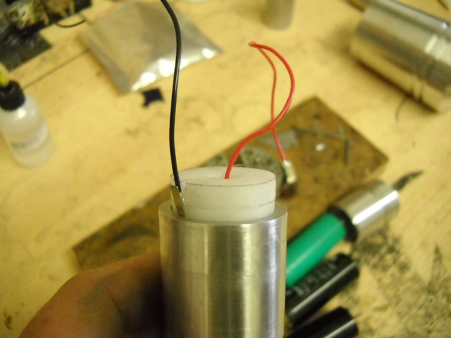
Now at this point some of you may be wandering, what is he going to use for a driver? It may surprise you, but the answer is simpler than you think.
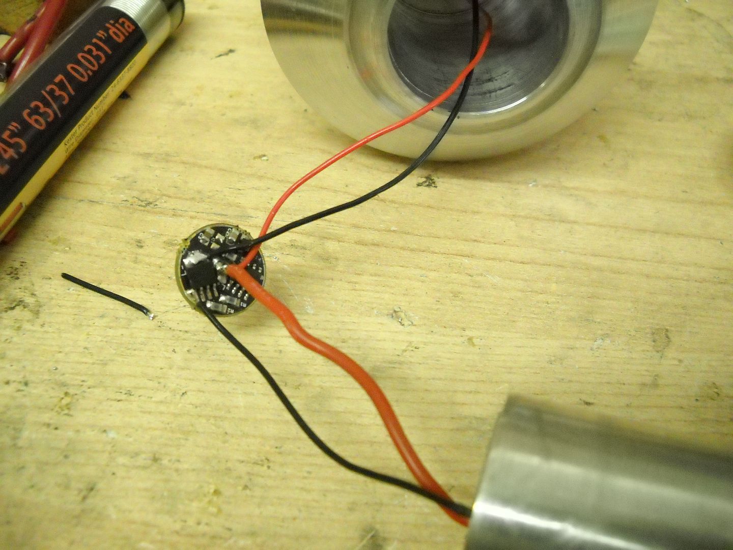
Yep, not even joking. 
There has been some speculation in a few threads as to what is the best way to go, and I am certainly not saying this is it, or that its the only way. Just IMHO the easiest.
I had sort of a leg up on this because I had made some of these boards with 16V components and finally got the nerve up to try this with an XHP-70 on a 12V sinkpad.
I was fully expecting to have to dumb down the max output by reducing the PWM level from 255 to like a hundred something. However after some careful experiments I found that the 70 had no issue running this way at max as long as the sinking was adequate.
So when my 35s arrived today I decided to go for it and the result is the same. The XHP-70s DD off the 4 cells run at around 4-5 amps or so depending on your cells and resistance etc.
The XHP-35s in this config run about 3.5 amps on high which is over 3 times the factory spec. I did decide to use some cells that have high internal resistance. My 5200ma Keeppowers. I really have no idea if the 35s could survive this on a set of Kongs as they typically drive much harder.
EDIT: Though the emitter can well handle the 3.5A current, controlled testing I did later showed 2.5A to be the dead fall for the emitter ( ie nothing to gain above 2.5A) so I dialed it back to 2.5 A by changing the PWM max to 180. :)
Anyway on we go....
The reflector I had pictured at the top is one I bought because it was deep, but it did not focus the way I wanted so I carved up a Courui DO1 reflector instead.
9/15/2015 UPDATE
Ok men time for an update.
I figure its time to let everyone know what has been going on. Long story short I had this light basically all built, looking how I wanted etc, however as it turns out the XHP-35 and courui reflector combo was not what I was hoping for either.
The reflector was doing its job, and I did get about 255,750 lux with the combo, but the over all output of the light was very disappointing. The XHP-35 offered up only a meager portion more lumens that a U4 bin XML2 ( a few hundred . This is all fine in a small light but in a horse this size it really just felt hollow.
I will go ahead and post a couple of shots of what the light did look like because its almost exactly what I had in mind when I started this project. I was going for a sleek wine glass/regal type look.


That said it was time to fully reboot.
As much as I love the tapered down head design in order to pull off the next revisions I had only one choice. Go BIGGER!
Ya I know as if a 3.5" head diameter is not large already, but I wanted to incorporate a reflector I know I can count on to get the job done.

For those of you not familiar with this reflector it is the LUM 5-90
http://www.illuminationmachines.com/products.php?id=9
I realize a few builds have been done with this already, but I think I can still squeak out a bit of an edge over the competition.
So, onward and upward we go...
As sad as it made me to have spend all of the hours boring and shaping that first head from a solid piece I knew I had to have an expansion. So I got some more stock that was another inch round (4.5" diameter).
Next I cut a bit off the head and threaded the end of it.

Then threaded and shaped the expansion.


I also threaded the end for a bezel this time since I did not like the set screw thing.
Since this emitter is going to be driven very hard and I want to get every last drop of output I can from it a massive slug will be needed.
The body of the slug is made from aluminum and has a 1" x 1" piece of copper pressed into it.


Doing it this way will allow me to transfer heat both to the head and the body directly since each will be threaded in/on to the slug with a generously long portion of threading :)
This time for the emitter I decided to go with a tried and true performer. A de-domed XHP-70. Only a direct bond to the sink will do so its time to grab the torch.

9/17/15 UPDATE:
So in the beginning I was going to just have this light be a twisty, but the mode changing was not all that functional. I also really dont like the feel of a top heavy light so I decided to solve both of those issues by making a thick heavy copper housing for a clickie switch.
Bored out the tail.

The battery end.

Pressed fit together


Now we have a balanced light, and and awesome control mechanism.
Since I now have a lot of the extra space in the body use up with that tail cap I got rid of that acetal plug and made an aluminum one. The driver will now be housed in this rather than the head.


Time to finish up the head.
Here is the sum total of the parts for it.

With the adapter part way in.

And the adapter on the neck of the light

9/17/15 UPDATE #2
I'm gonna go ahead and add some more to this so we can move things along.


Candle Mode :)


Now it would seem that with this done, it would all be over right? However before we roll out to beam shot alley there is one more thing I'd like to mention I think many of you may find interesting.
This goose still has one more golden egg left to give.
Let me give you a hint. In some of those pictures there is no lens in the light and in some it is.
Can you tell which ones? I cannot accept that there is a tell. If you look closely the ones where the o ring is visible ( actually a piece of wire since my o ring is not here yet) its there.
Whats so special about that you say? Plenty of good AR lenses can be photographed this way.
Well I say to you, where do you get one this size then..... Nope not a cheap sorry, barley thick enough to catch a rain drop camera filter. Its some thing else.
2.25mm thick.

An crystal clear. ( accept for a light purpleish haze if you turn it right)

Lets have another look. Just to be fair I will tell you the lens is installed in this picture.

Any one care to wager a guess as to where I got this beauty? What its special about it?
9/26/15 UPDATE:
Allrighty, time for the final chapter.
First off the reveal on this awesome lens. At this time I must give credit to my beautiful wife since it was actually her idea.
She comes in the shop from time to time to see what I'm up to and when I mentioned to her my difficulty with the super thin UV coated camera lens she said "what about a picture frame shop? They have anti reflective glass".
So I called around and managed to source some. However some shops use what I would call an imitation which basically amounts to a frosted glass that does eliminate glare ("anti glare" vs "Anti reflective" I guess), but actually cost you light rather than improving pass through. This is what I ended up with the first time, but after I called around a bit more I found a shop that said they use "museum glass" which is AR coated on one side and UV coated on the other. He also confirmed the purplish haze like true AR lenses have so I went and got some.
This time with glass in hand I went to a glass shop where they had a circle cutter. The guy did have some trouble cutting the glass ( perhaps because of the coating), but shortly after I left with a pair of lenses just the size and thickness I need.
This happens to be the brand of glass that I got.
Its not cheap but is worth it IMO. I called Michael's today and they also carry this glass.
Moving on I brought along a few beam shots:)


This next one is close to 300 yards.

Control Shot

The road ends before the light beam does.

Finally some numbers.
The Arc of Josiah gave me an impressive 266,750 lux at one minute. I am quite pleased with this for a quad die emitter.
Lumens at one minute were 5281 at one minute! Again very pleased.
Over all I could not be happier. I got 30K more lux than I had with XHP-30 and more than 3 times the amount of light.
I'm so glad I did the controlled testing with this emitter because it gave me an edge. I had thought before that the max for an XHP-70 was around 4 amps on a 12V star or 8 on a 6V, but the test showed gains up to 6A on the 12V star.
https://budgetlightforum.com/t/-/35480
Loaded with the 26650s I get 5.7A at the tail on this light which is just about perfect.
Thank you all so much for watching, and for the support. A Huge shout out to _the_ for hosting the contest this year, to Old lumens for the original plan, to those to donated prizes, and of course to SB56637 for crating this awesome forum we call home!!
 . Sure seems like it would take a lot of pressure and consistency to get it right.