A look at QI (Wireless power transfer)

A look at QI (Wireless power transfer)


Wireless power transfer does not mean you can transfer power a long distance, you nearly need contact, but there is no connectors that needs to mate. This means that the advantage of wireless power is not charging at distance, but that there is no connector, you just drop the phone on the charger and it will charge.
Lets first take a look at the products I will be playing with.

Receiver


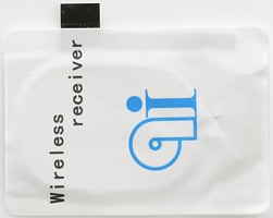
The receiver is a thin square (1.2mm thick and 44*62mm (excluding connection)), most of the contents is a coil, but there is also some control electronic. I got this model because it looked easy to connect to my test system, I just had to solder two wires onto the contact points.
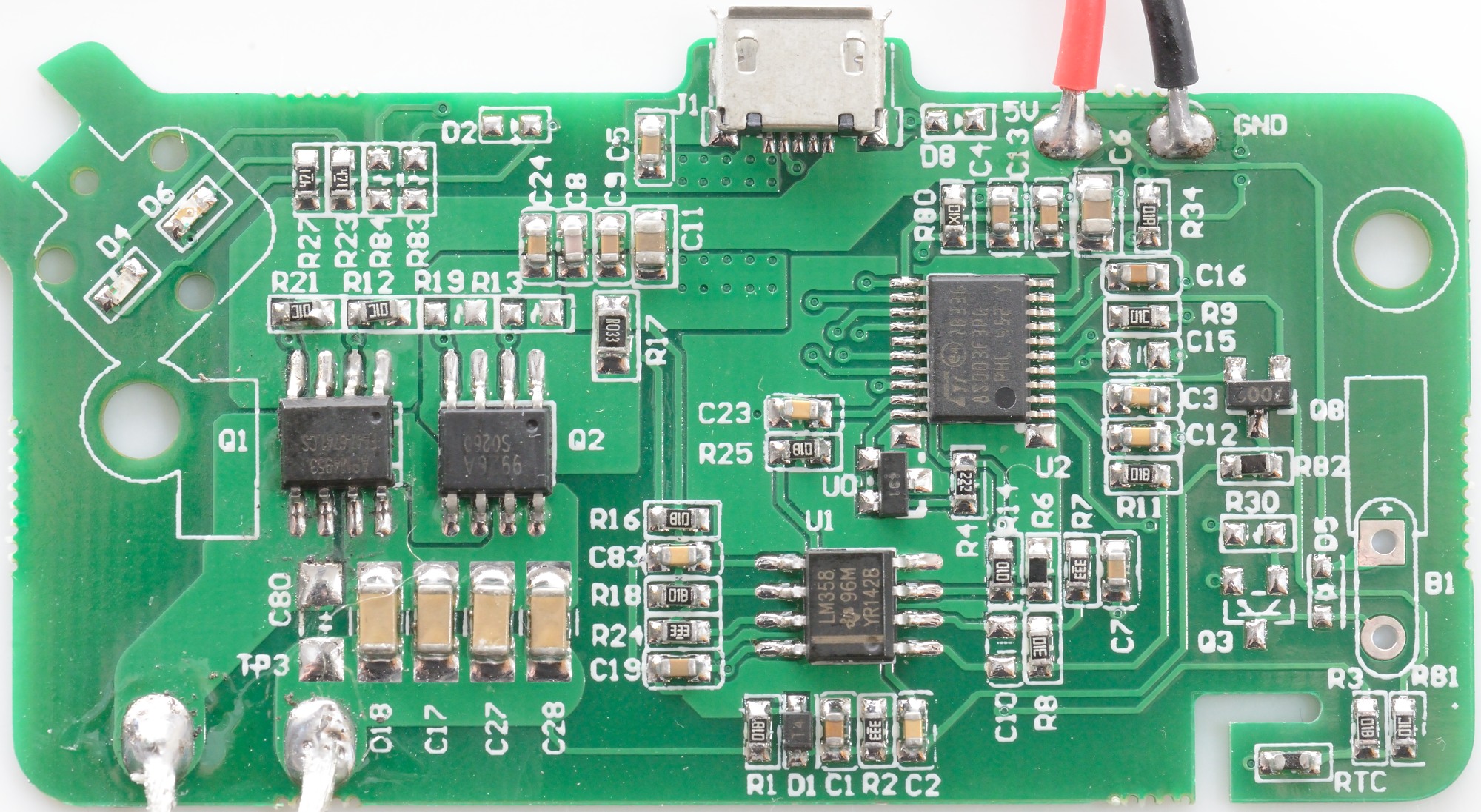

Transmitter #1


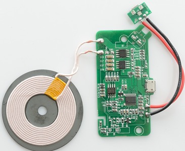
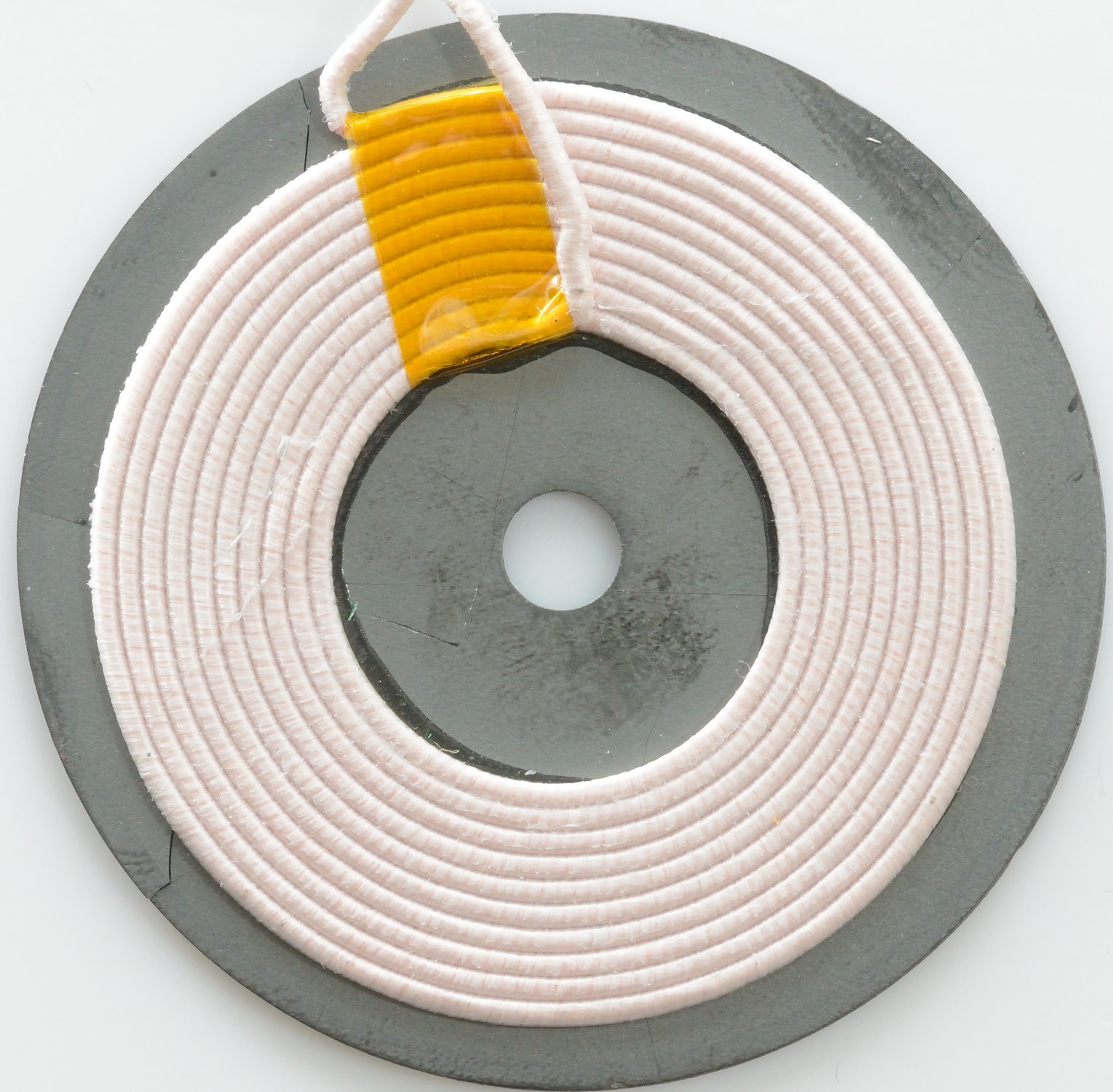
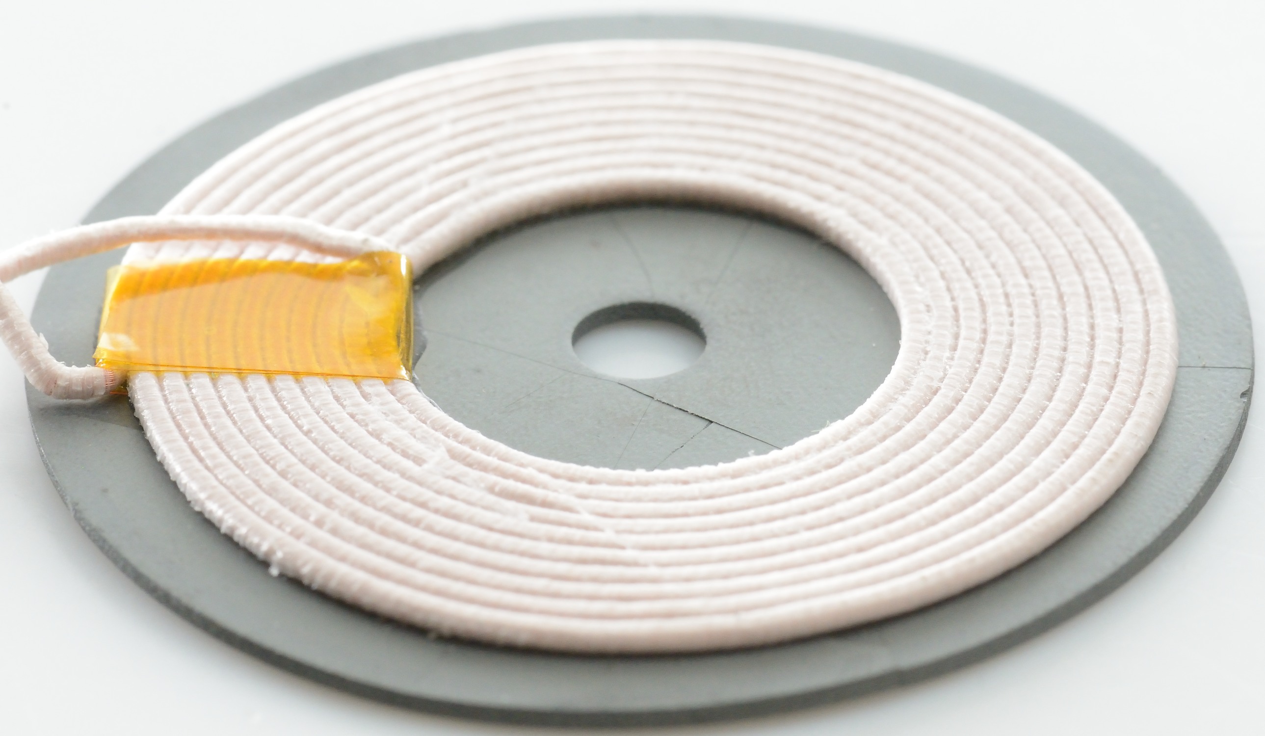
The first transmitter is a loose circuit board and a transmit coil.


Transmitter #2


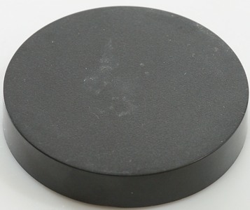
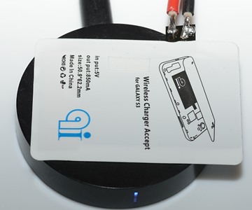
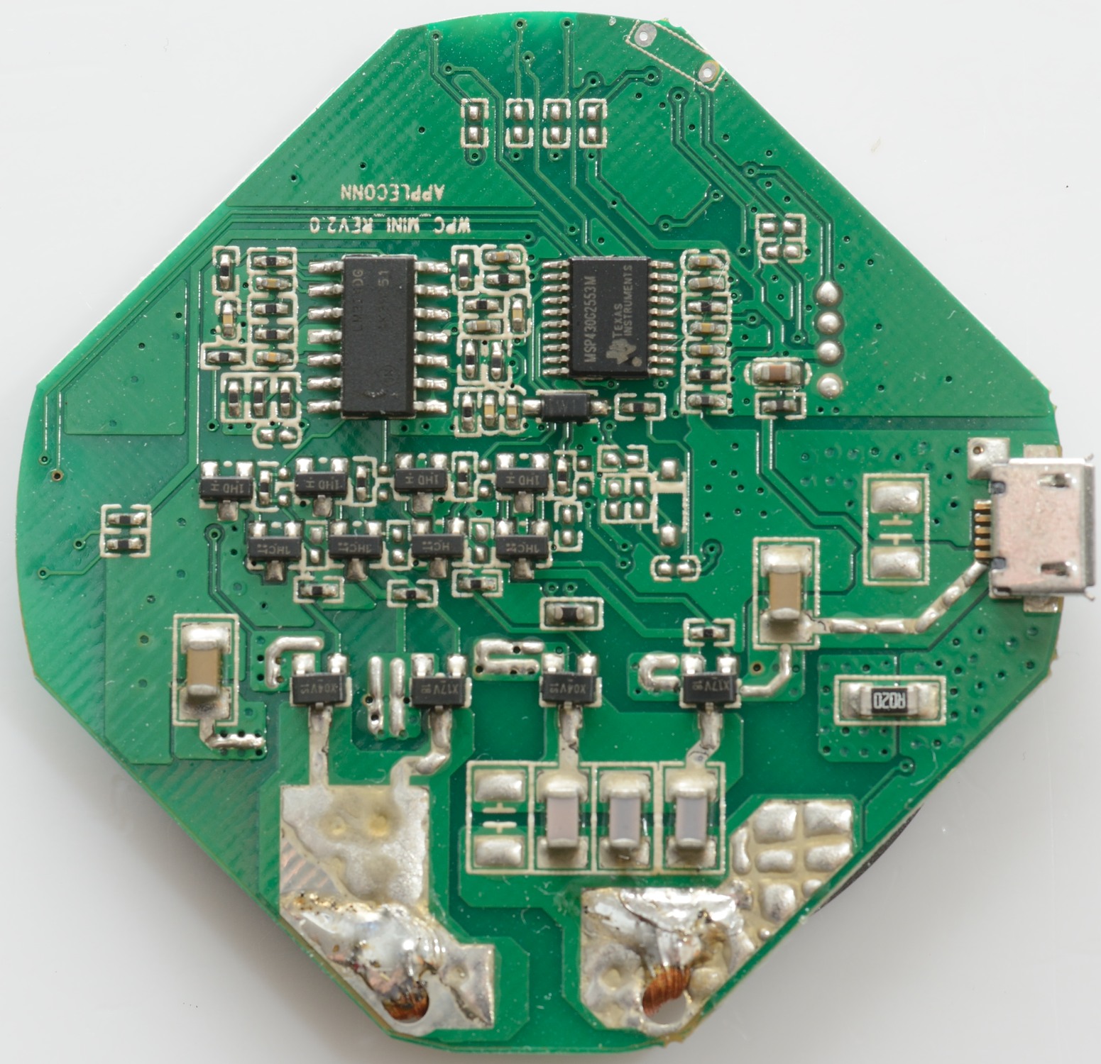
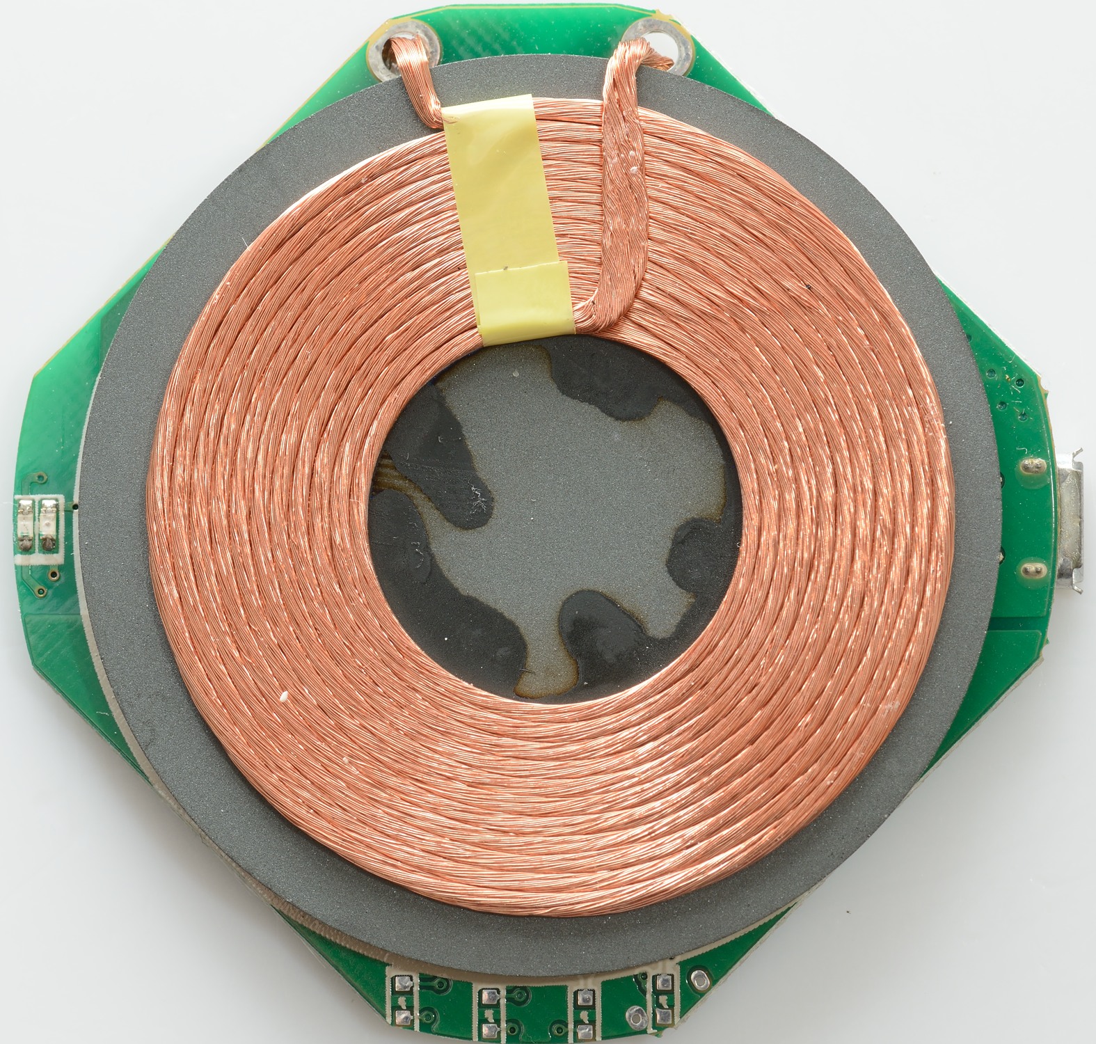
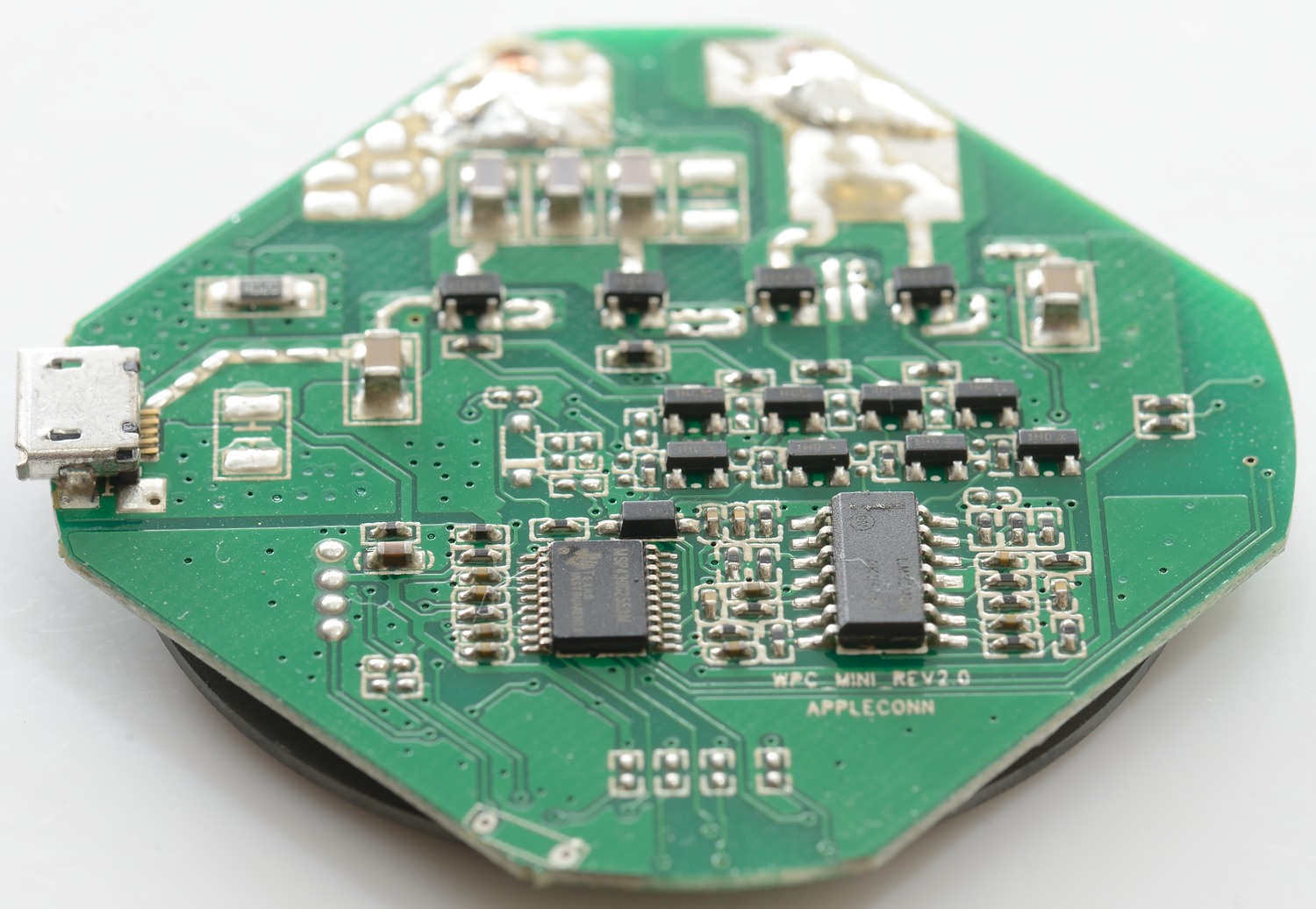
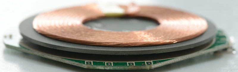
The second transmitter is a puck.


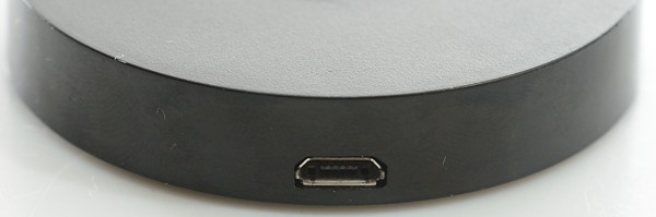
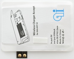
On one side of the puck is a micro usb connector for power input.


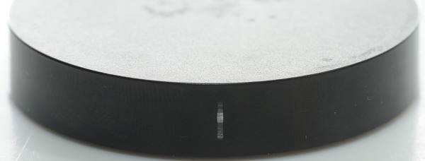
On the other side is a led to show status: Red is powered, blue is connected.


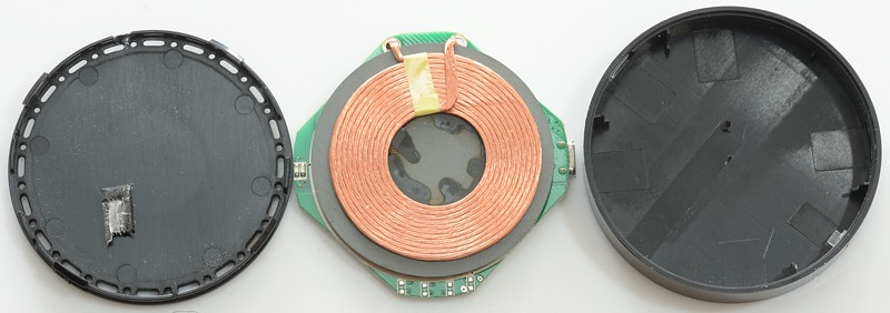
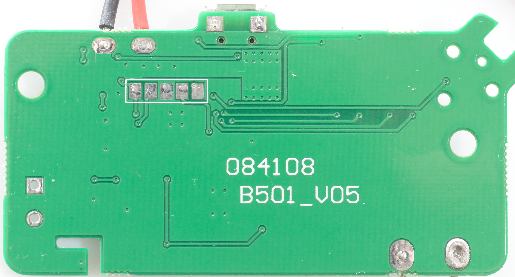
I could just open it.


Performance test

Like always when moving or converting power there will be some loses, how bad is it with this technology?


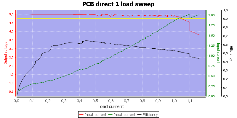
With the antenna placed directly on the coil I get about 60% efficiency in power transfer.


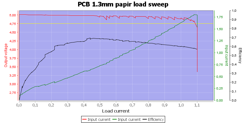
I tried to increase the distance with some paper, it did not reduce the efficiency.


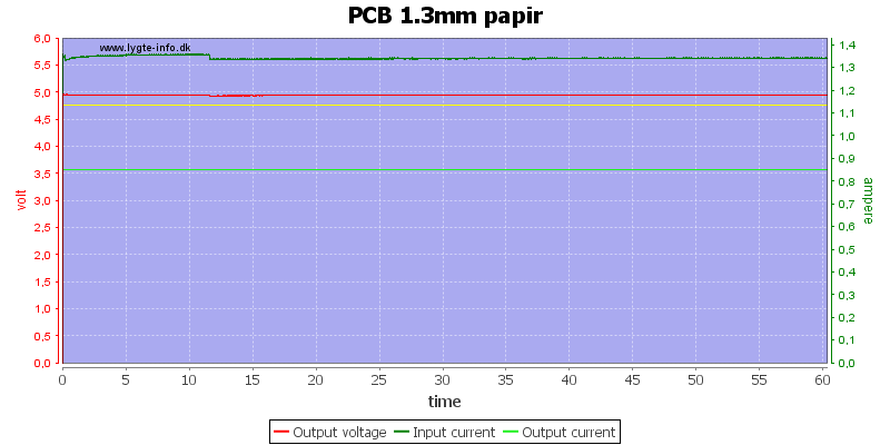
No problem running an hour with full power transfer (I did have problems without the paper).


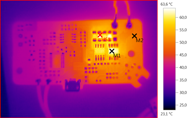
M1: 63,5°C, M2: 50,1°C, HS1: 63,6°C
Some of the power is lost in the drivers and in capacitors.

Some observations on transmitter #1

  • Coil must be the correct way for it to link up, i.e. the flux direction is polarized.
  • Current when not linked is about 10mA with 30 and 130mA spikes.
  • Current when linked but unloaded is minimum 100mA
  • Very difficult to get a stable link.


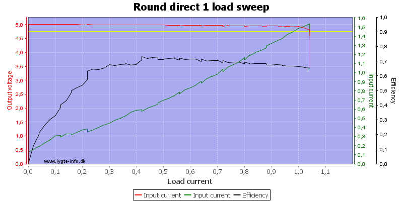
The round antenna has better efficiency.


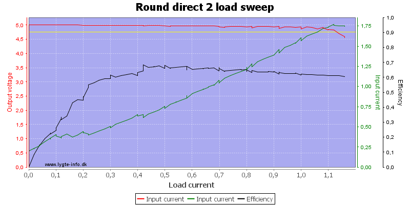
I tried moving the receiver antenna a bit around on the puck, it did change the maximum current and efficiency.


This position has lower efficiency.


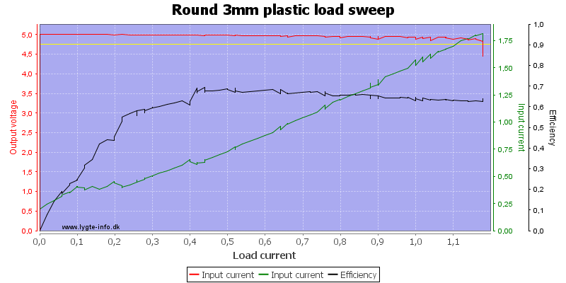
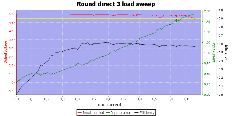
How does it work if I increase the distance, first try was 3mm plastic, it works without any problems.


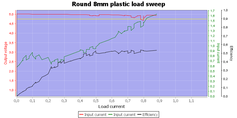
But with 8 mm plastic I am nearly out of range.


Running an one hour load test worked fine.


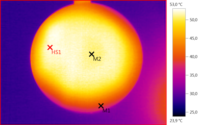
M1: 39,0°C, M2: 51,0°C, HS1: 53,0°C
The heat is distributed over the surface.

Some observations on transmitter #2

  • Coil must be the correct way for it to link up, i.e. the flux direction is polarized..
  • Current when not linked is about 12mA with 100mA spikes
  • Current when linked, but no power is drawn 130mA to 500mA a bad connections requires more current.


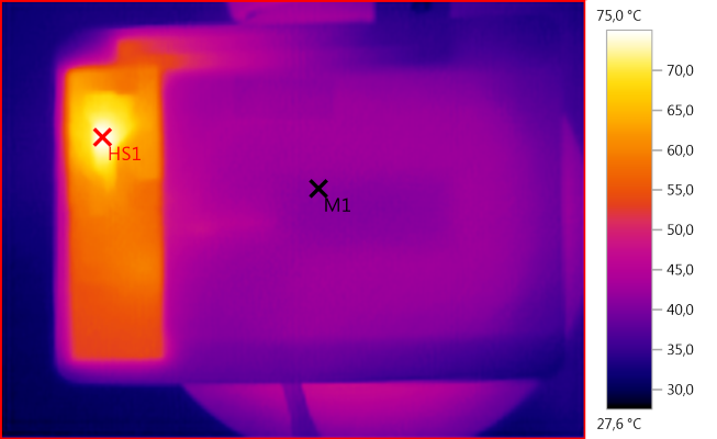
M1: 41,3°C, HS1: 75,0°C
The receiver has some electronic inside that gets fairly warm.

I did also try with iron, copper and aluminium between the sender and receiver, it was not possible to transmit through it. Even a piece of aluminium foil was enough to block the transmitter.
But it did increase the current consumption:


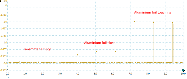
Current spikes without foil and with foil.


How does it work

Using my oscilloscope I looked a bit on the waveforms, first from the round one.


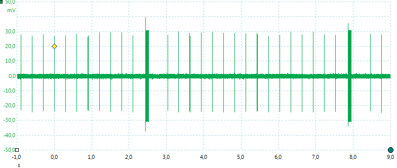
When no receiver is within range the output is mostly off, it will just turn on once each second.


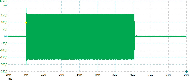
This "beep" is 0.06 second long. The idea is that it is long enough to power up a receiver and let it answer back.


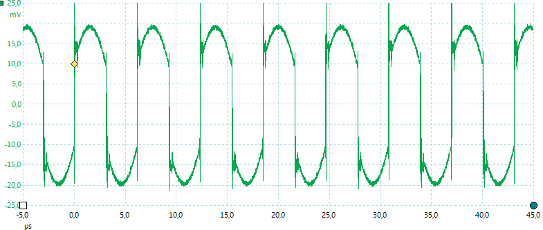
The actual frequency is about 164kHz.


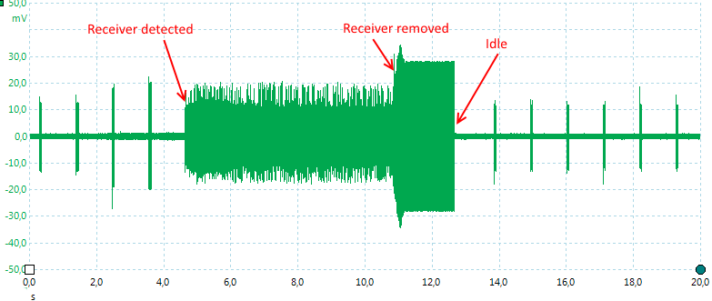
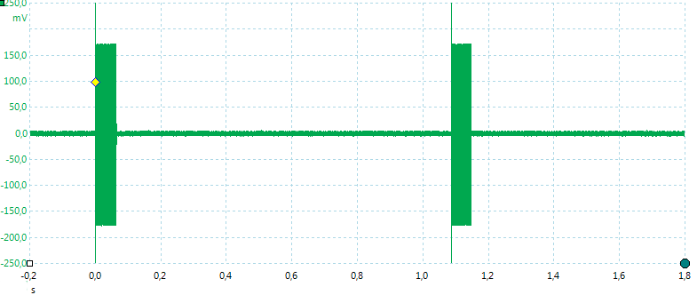
Here is a full cycle with a receiver detected and then removed again

I did also look at transmitter #1:


It "beeps" at a faster rate and sometimes it has longer beeps.


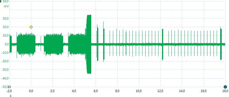
I did frequently have connection problems, here is one where it did not succeed.


And here is one where it got a connection and I removed the receiver again.


A bit more about how it works

The system is controlled from the receiver, i.e. the receiver sends commands to the transmitter about power level, when no commands are received the transmitter will go into idle mode. These commands are modulated into the transmitter frequency, by the receiver.

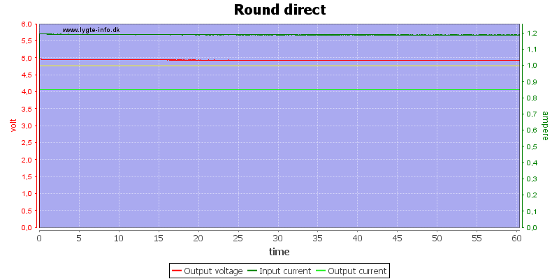
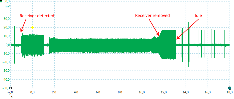
Here is an example where I switched on a 0.85A load:


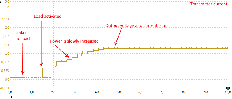
It takes some time for the system to react, then the receiver starts asking for more power until voltage is up again and it is supplying the current.

This makes the system fairly safe, it is not radiating a huge amount of power when idle, it will only transmit the beeps looking for a receiver. When the receiver is placed on it the power is increased as much as the receiver needs or too the limit of the transmitter.
The frequency used is the old long wave radio frequencies where the transmitters used about 100000 times more power and much larger antennas


Heat

The efficiency is between 60% and 70%, the lost power does not just disappear, it manifest itself as heat. This heat is generated in both the transmitter and the receiver as can be seen on the IR photos.

Depending on environment and what is being charged this can be a problem, LiIon batteries are usual supposed to be charged below 50°C (A phone is supposed to have a temperature sensor that will shutdown charging if the battery gets to hot).
If the temperature will be a problem depends on how fast the phone tries to charge and if it is smart enough to reduce charge current when things heat up.

There is also another detail when adding a charge path to some equipment: is there something in the equipment that interferes with the charging frequencies?

Here is a test with two phones without any QI charging patch placed on the puck charger:


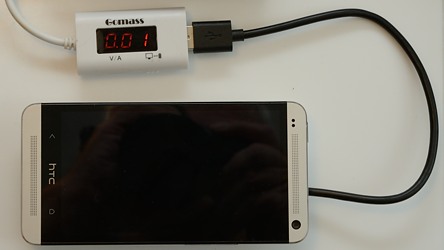
First with my HTC, even the aluminium shell do not give any problems.


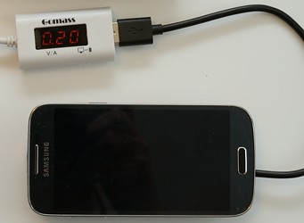
But this phone draws some current (The meter is not showing the correct value).


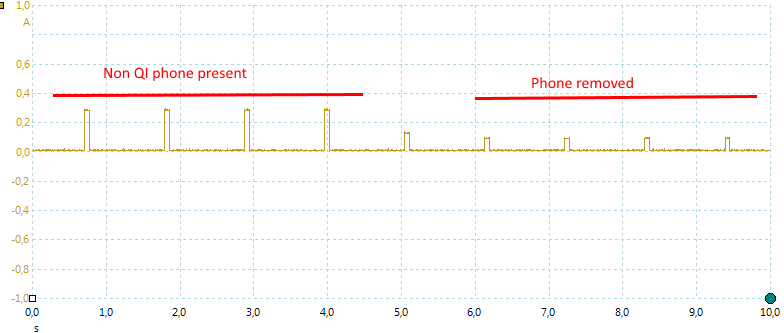
Here I try with my scope and it is obvious that the ticks are larger (i.e. with more power) when the phone is present. This, by itself, is not a problem, but if more power is required during the charge it means more loses and more heat. More heat means higher temperature!


Conclusion

For something that needs to be charget often I like the convenience of this. With the significantly reduced efficiency it is not really smart for devices that use a lot of power, but for a mobil phone or other small devices it looks very nice.

The charging speed will probably not match a connected charger, but with a charging path close to you bed this may not be a problem.


Notes

I only tested with one receiver, if I had used another receiver the result may have been different.

i like the idea of being able to just put down the phone on a wireless charger and not have to connect anything. haven’t tried it though.

I use a QI charger with my phone. It is so easy to use compared to fiddling with a micro USB :slight_smile:

Thanks for the excellent write up and explanations. Much appreciated!

How does the receiver attach to your phone? Tablet?

I love this idea. I have broken more screens and USB connectors forgetting they are plugged in, or someone walking by and snagging the charge wire. This looks like a good solution for the accident prone :slight_smile:

Depends on the phone:

  • Some phone has already one build in.
  • The above patch will fit between the back cover and the phone and the phone has a connector/contact points for it.
  • You get a new back cover with it build in and it might fit a connector/contact points inside the phone.
  • You buy a patch and glue it to the back of the phone, it is connected to the usb input

Try do a google search on you phone model and QI to see if anything pops up.

Do not expect anything to work if the phone has a metal back cover. This is a problem for me, I love phones with metal covers, but would like to get QI on my next phone.

Great timing, I just ordered some QI chargers and receivers a few days ago. The one thing that concerned me from the reviews were reports of batteries getting overheated, but it wasn’t clear whether it was too much charging current to the batteries or just trapped heat from the receiver. Looking at your thermal shot of the receiver, it looks like they need to do some more work to keep the electronics cooler.

KuoH

Very nice little look into qi charging. A while ago I got one of these chargers and glued 4 magnets inside the puck directly adjacent to the coil and mounted the puck on an incline as a desk charger. My phone has strategicly placed steel plates in the back around the antenna so I just place my phone on the puck and it sticks to it and charges. Never measured current draw before and after but now I’m thinking I will do so. Also I did not come up with the idea for the dock, there’s a thread on xda about it. My phone is the nexus 5.

I hope the next Nexus will have qi. I want to uprade from my Optimus G which is the bastard sibling of the Nexus 4.

Very informative write up.

I had a Samsung Note3 with the Qi backplate and charger base, and despite being heavy on current draw (1.6A 5V) It didn’t charge my phone nearly half as fast as with a 2A charger connected. It also got very hot…

There is plenty of room for improvement for this technology, I’m sure one day it will have close to full efficiency and probably replaces the physical connection in all the devices. The true “wireless era” is only a few years away.

I did not thing about the heat, I have just added a chapter more to the article about it.

No need to plug to charge?
I like the idea but only few mobile phone support that function :frowning:

Love wireless charging on my Lumia phone!

Ordered two wireless chargers from Ebay, one was cheapest square one - didnt work, phone got very hot but was not charging, while the other one, cheapest round one, chargers very good!

I like the convenience of wireless charging - if your phone spends most of its time on the desk or at least significant time, you can always place it on charging pad and you will less likely have to worry about your smart phone running out of battery at the end of they day ;)!

Only drawback that on some chargers you need to place phone on them pretty accurately to make contact as well as external silicone shells might add 1mm or 2mm to the distance between charger and phone thus making important perfect placement of your phone on charging pad!

I bought two Qi chargers, one was heating up battery and not charging at all, the other is charging very well and the battery get only warm, not hot. I charge it with the cable pretty rarely so cant say for sure how much warmer the battery gets when Qi is being used, but it appears that it does get warmer, but not to the point of dangerously warm IMHO.

Qualcomm supposedly have found a way around it:

https://www.qualcomm.com/news/releases/2015/07/28/qualcomm-becomes-first-company-enable-wireless-charging-mobile-devices

This is finally the practical version of Nicola Tesla’s scheme of world broadcast power, without the disadvantages like burning down all trees that happened to be in resonance.
It was also my high school science fair project. I lighted a flashlight bulb with my train transformer with cardboard between the coils of wire. Not very neat, but it got me the extra points in my physics class.

If you guys are tired of plugging in usb cables to charge, check out Sony Xperia magnetic charging cables, they work great & just as fast as normal usb charging.

The only downside is they are only available on some models of the Xperia line. And unfortunately not on the latest (for sale ;)) Xperia Z3+

The problem of heating batteries during wireless charging can be attributed to two things. 1) The thickness of shield plate behind the receive coil. 2) Whether the transmitter uses an attractor magnet to help guide and center the phone on the charging base.

The shield plate is critical for operation as it provides a path for the magnetic flux, concentrating it through the coil (and not through the phone). Thicker is better, but thicker means the phone is thicker, and its hard to market a thicker phone. And because thin uses less material, thinner is cheaper. But a thin receiver shield can work well enough... except when it's used with a magnetic centering transmitter. This is because all magnetics have a saturation point at which they can no longer conduct magnetic flux, related to their volume (in this case thickness). The field from the magnet shifts the saturation point of the receiver causing it to be much less efficient.

The result is the shield begins heating and the flux finds a different path to follow, like through the battery. :(

Unfortunately the battery is not particularly good at magnetics, and also heats-up due to something called "eddy current losses". This is how inductive cooking works.

Because the wireless receiver is usually very close to the battery, heat generated in either will cause a bad affect on the battery.

Bottom line: choose a charging pad without a magnet. And hope the Qi receiver supports thermal management (it should). Display of the "Qi" logo implies adherence to the standard. (They would never lie about that , would they?)

That would be very interesting to me if I were interested in cell phones. Sounds like a good approach would be to calculate all that with the finite difference time domain method. It was first published by a man I worked with at Lockheed. It isn’t that time is evolved directly, it is that the saturation mixes frequencies so frequency domain methods are not directly applicable.

Do you know if the receiving coil/chip has a parasitic draw?

If you are thinking about current going from the phone into the patch, I have not measured it.

I do not believe it is relevant, the patch is not mounted directly across the battery and the phone is not supposed to boost battery voltage and then supply it to the patch.