Orico 4 port USB charging station DCP-4US
Official specifications:
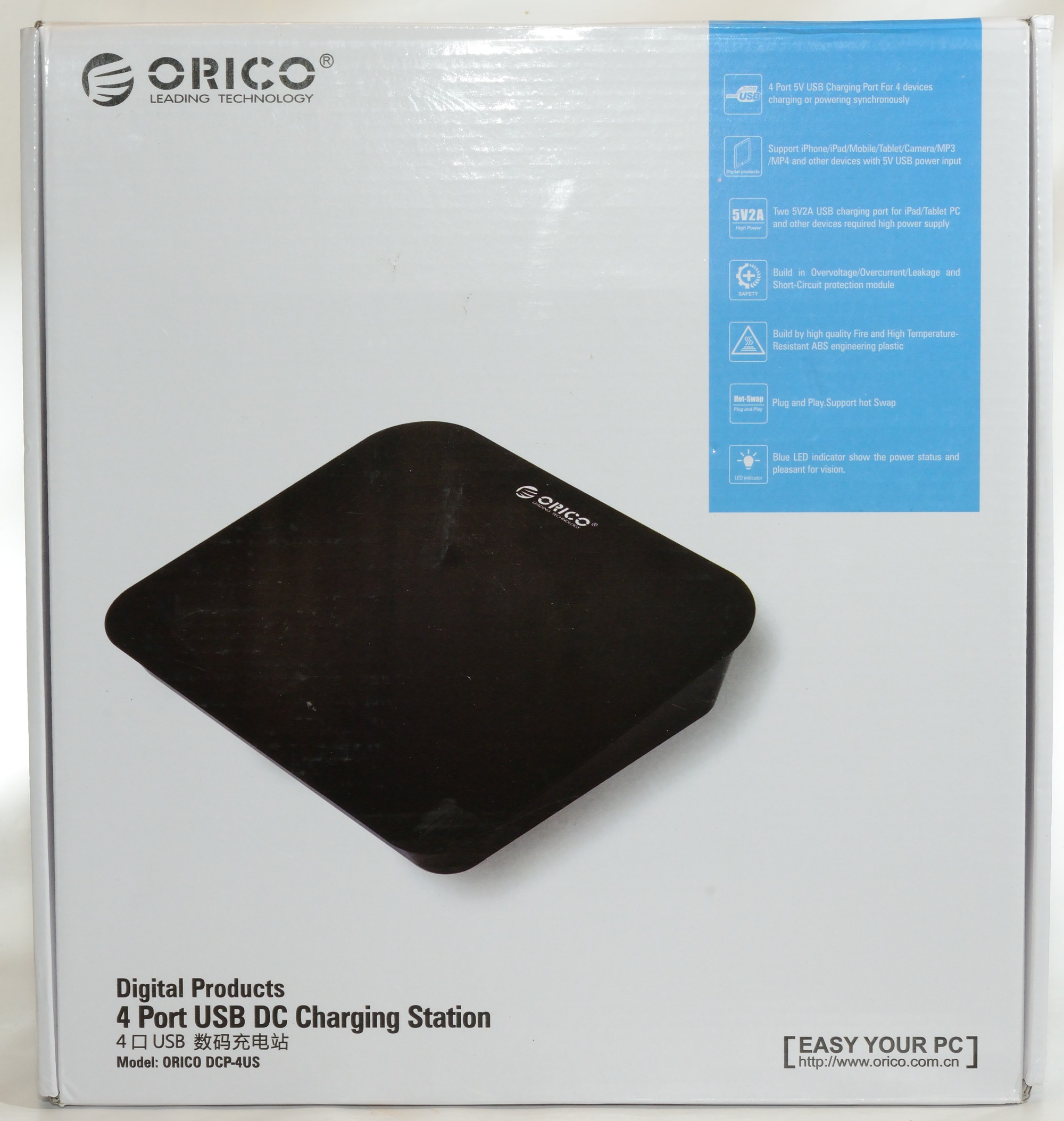
- Product material: High Strength Fire & Heat resistant Engineering ABS
- Product color: Black
- Dimensions: 225x260x60mm
- Weight: 670g
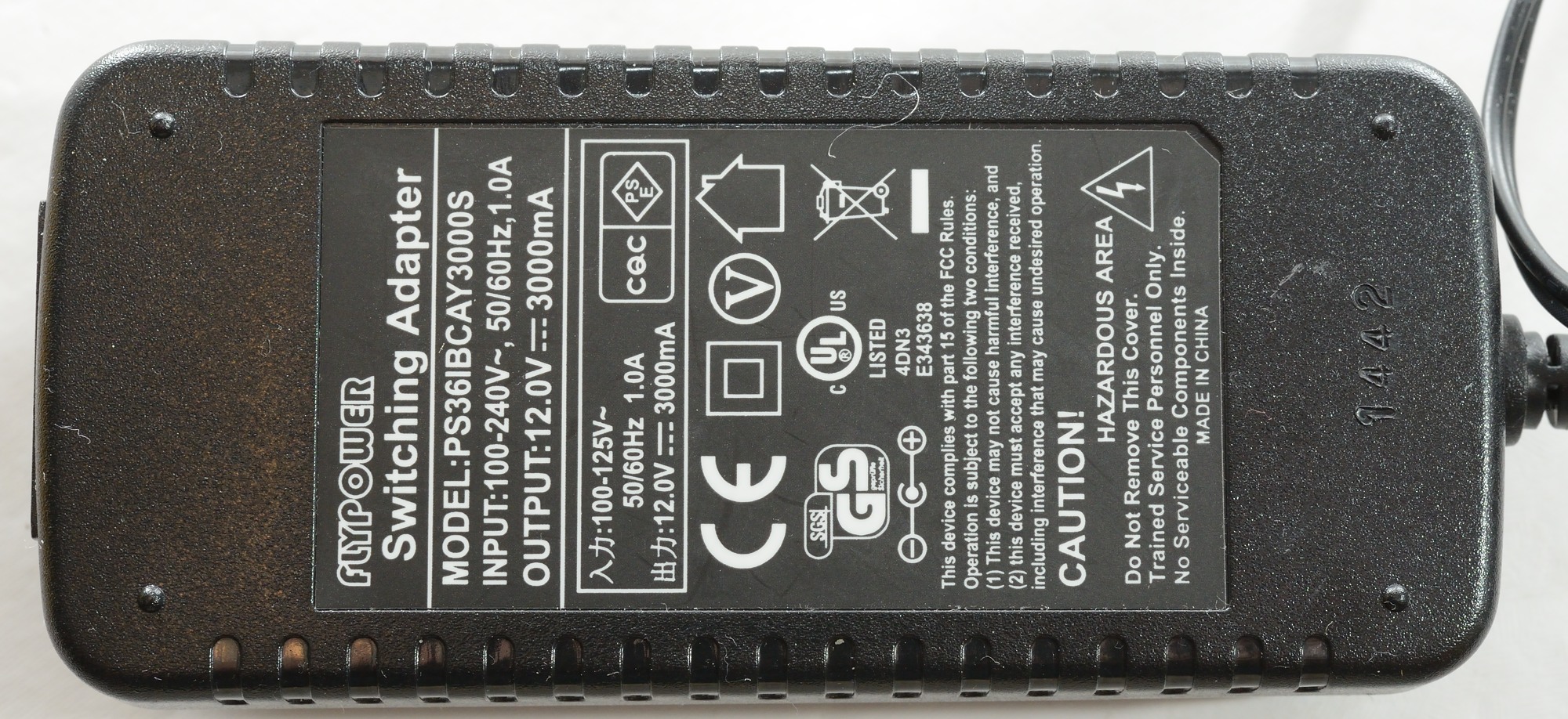
- Input: 100-240V 50/60Hz
- Output: 5V1A x 2 and 5V2A x 2
- Certificated: CE, FCC, UL, CCCC, SAA, PSE
- 35W USB charger
- Intelligence charging technology
I got this charger in a big cardboard box.
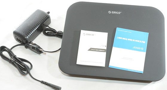
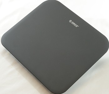
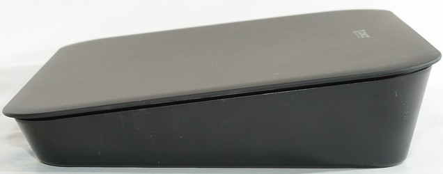
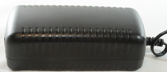
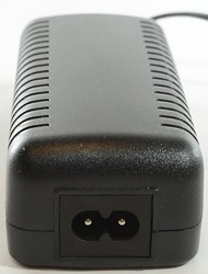
The charger is fairly large and has an external power supply.
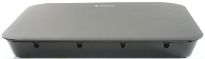
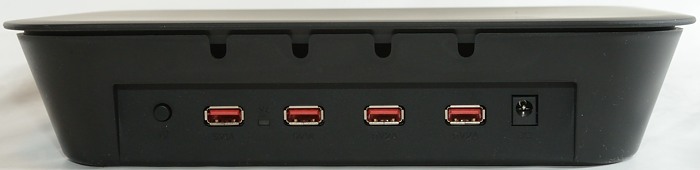
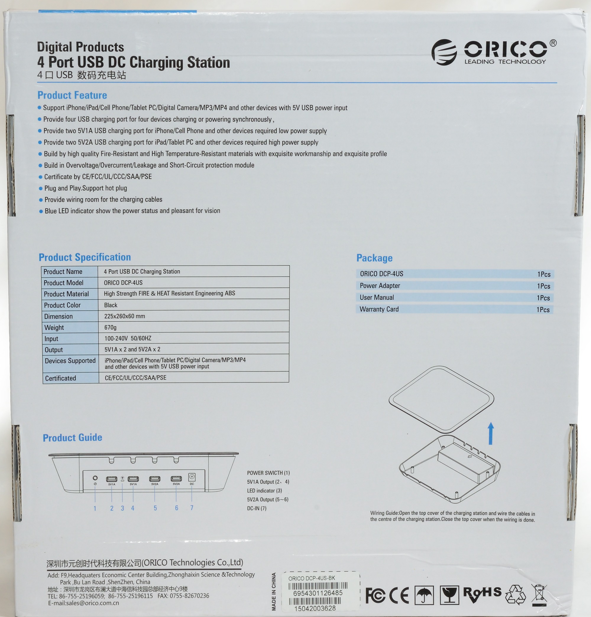
On the back is power switch, 4 usb ports, blue led, 12V input
Under the lid is space for cables.
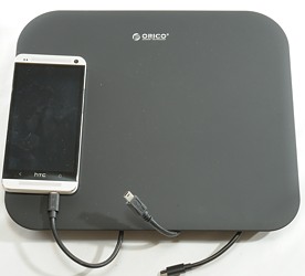
There is space for a couple of phones on it.
Measurements
- Charger + power supply power consumption when off (Switch on charger) 0.16 watt
- Charge + power supply power consumption when idle 1.5 watt
- 1A ports are coded as Apple 1A
- 2A ports a automatic selected up to Apple 2.1A.
- There is two output circuits, one for 2A ports and one for 1A ports.
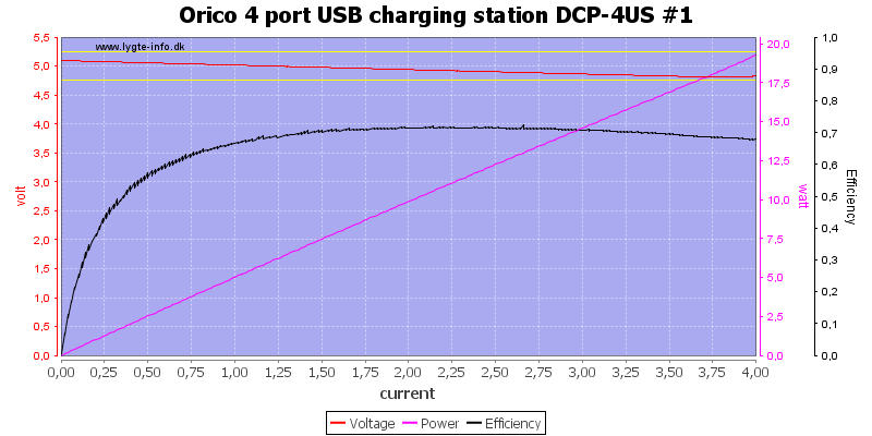
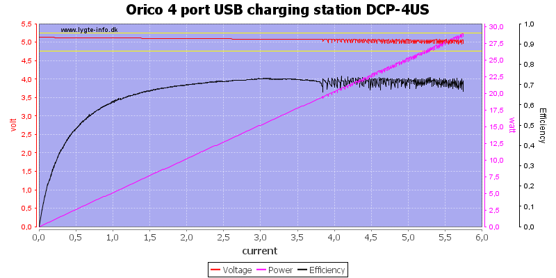
There is no individual overload protection on the ports. The efficiency is on the low side, this is because it has two power supplies in series: First the external mains -> 12V and then the 12V -> 5V internal switcher. In that light the efficiency is good.
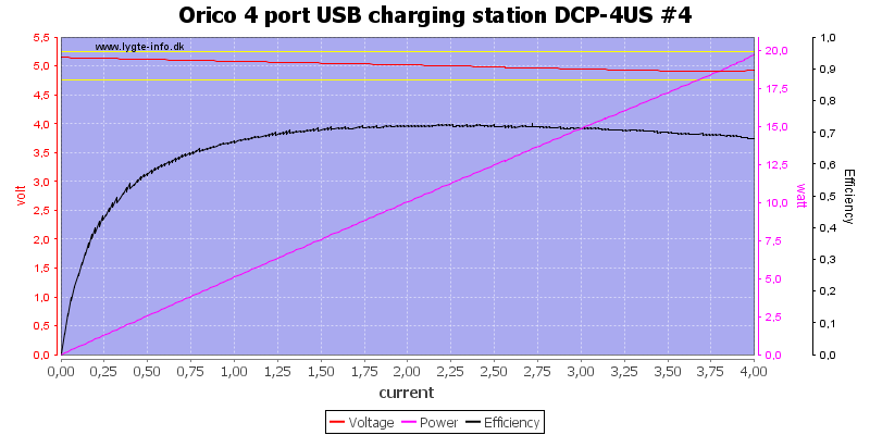
The 2A outputs looks exactly like the 1A output.
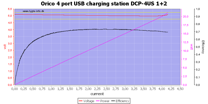
Running two outputs in parallel reduces the voltage drop in the connector and I could use larger current, but hit the overload protection just above 4A. This protection is for a pair of ports.
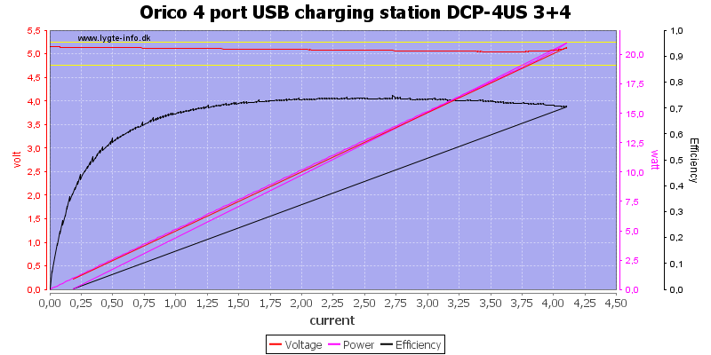
Running all four output is parallel did not give double the current, probably because there is a small difference between the voltages (I need an electronic load more to do this correctly).
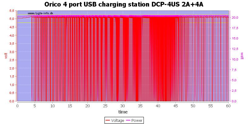
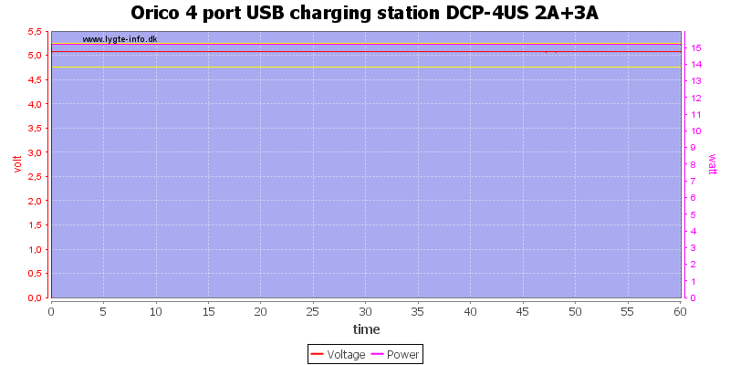
Loading the two 1A ports with 1A and the two 2A ports with 2A did not work, the output did shut down very often to cool a bit. The curve only shows output from 2A ports.
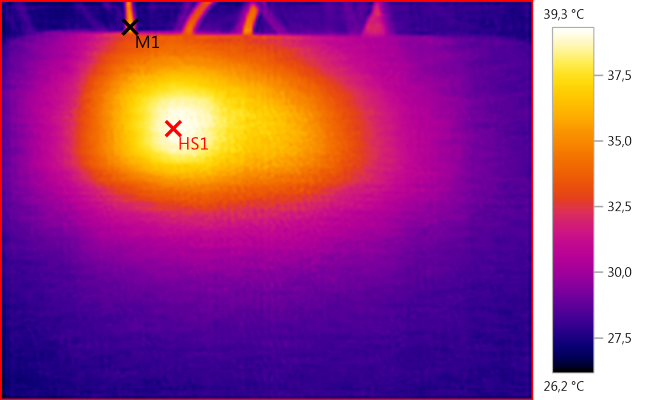
The temperature photos below are taken about 45 minutes into the one hour test.
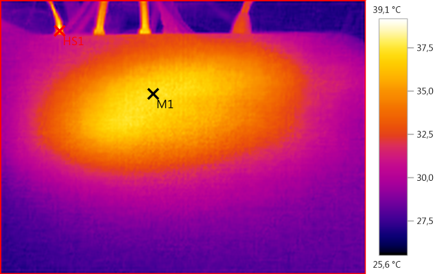
M1: 37,2°C, HS1: 39,1°C
The outside of the charger is fairly cool.
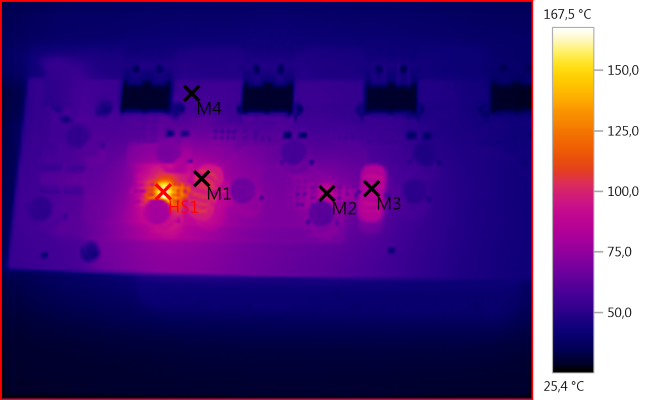
M1: 104,1°C, M2: 91,4°C, M3: 84,0°C, M4: 55,4°C, HS1: 167,5°C
But not the switcher IC for the channel with 4A load. This chip can handle up to 5A output current and will shut down if it overheats.
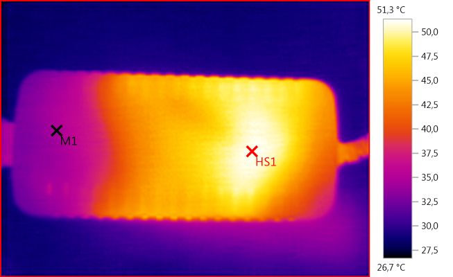
M1: 34,8°C, HS1: 51,3°C
HS1 is the transformer.
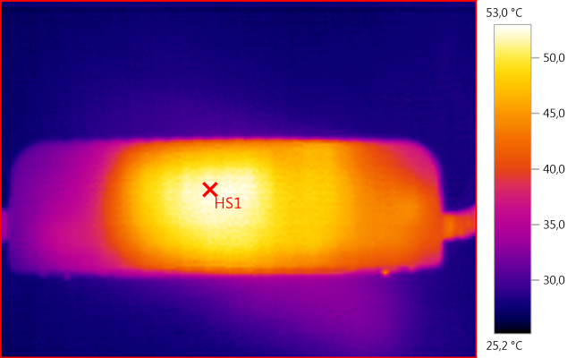
HS1: 53,0°C
HS1 is the heatsink for the mains switcher transistor.
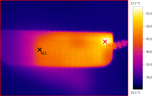
M1: 44,8°C, HS1: 57,7°C
I wonder about HS1, it must be from the rectifier diode, like most of this side. Maybe HS1 is because the white stuff is helping with heat transfer (See tear down of power supply).
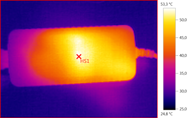
HS1: 53,3°C
Reducing the load to 3A on that switcher did help, now it can handle 1 hour.
The temperature photos below are taken about 45 minutes into the one hour test.
M1: 36,6°C, HS1: 39,3°C
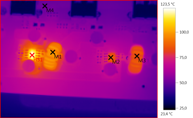
M1: 98,9°C, M2: 86,3°C, M3: 84,6°C, M4: 51,0°C, HS1: 123,5°C
The switcher is much cooler now, but still hot.
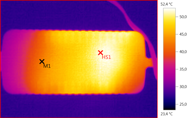
M1: 42,5°C, HS1: 52,4°C
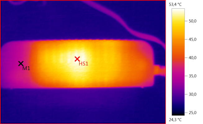
M1: 35,9°C, HS1: 53,4°C

HS1: 57,5°C
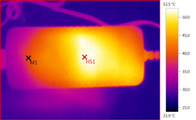
M1: 39,4°C, HS1: 52,5°C
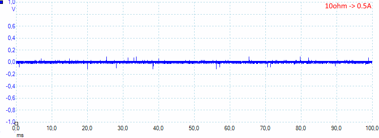
There is not much noise at 0,5A with 15mV rms and 280mVpp.
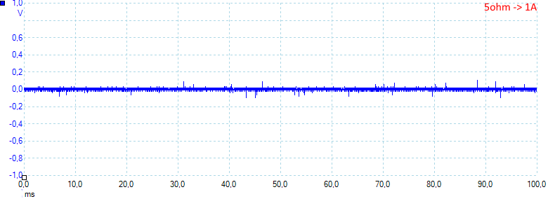
The noise is about the same at 1A with 15mV rms and 260mVpp.
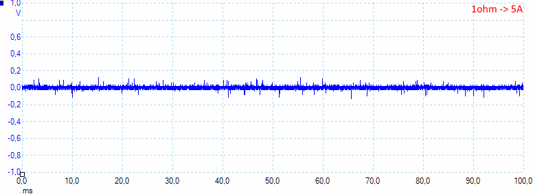
Before the chip gets to hot and shuts down it can deliver 5A and with very low noise: 22mV rms and 350mVpp.
Tear down
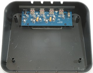
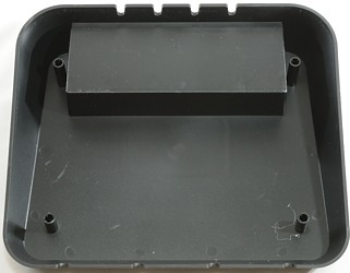
This is the easiest tear down yet, I could just take the lid over the electronic away. I do not like that easy access, but it is not really dangerous, because the highest voltage is 12 volt.
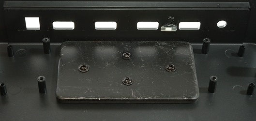
Below the circuit board is some metal to add a bit of weight to the charger.
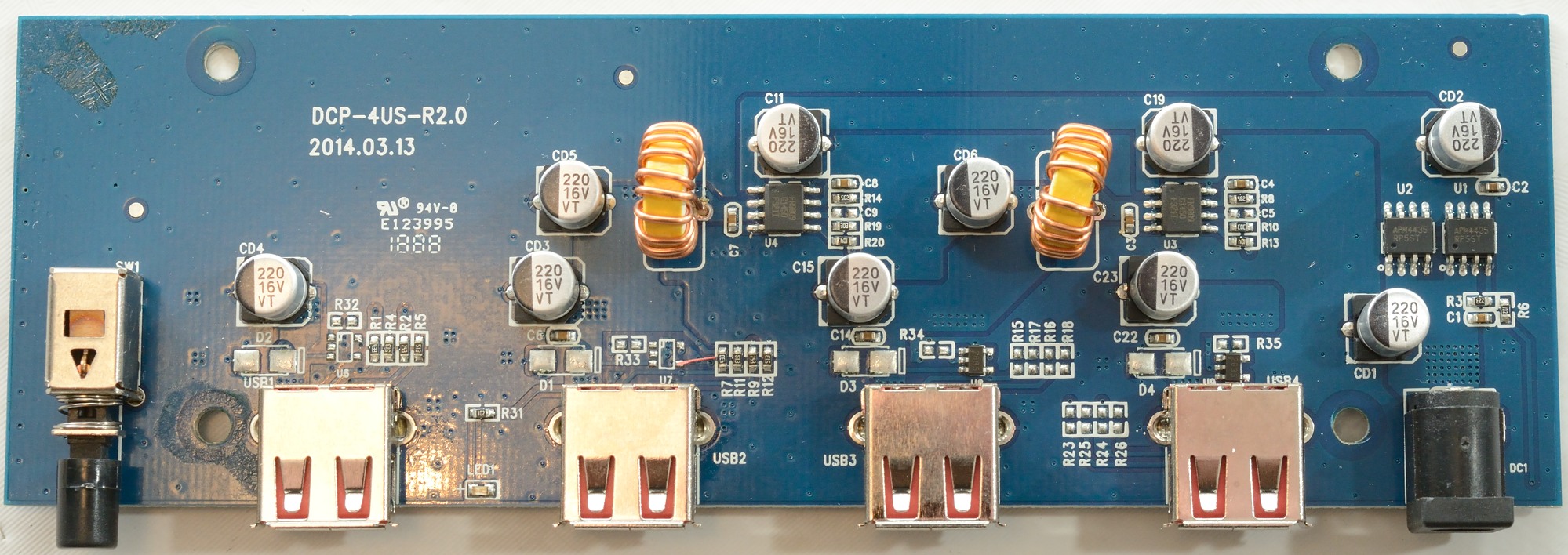
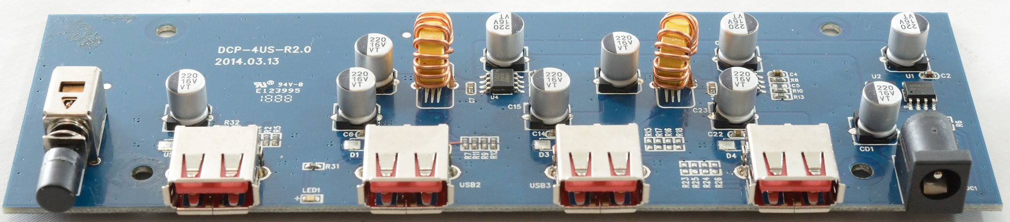
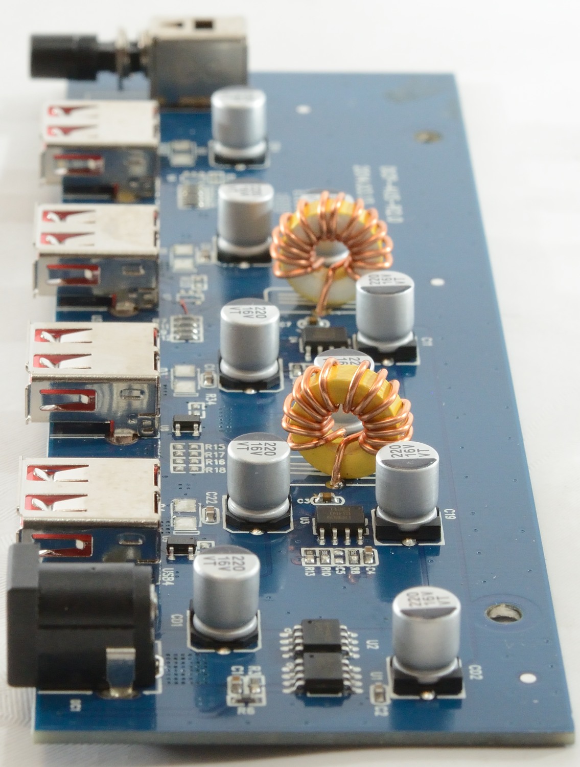
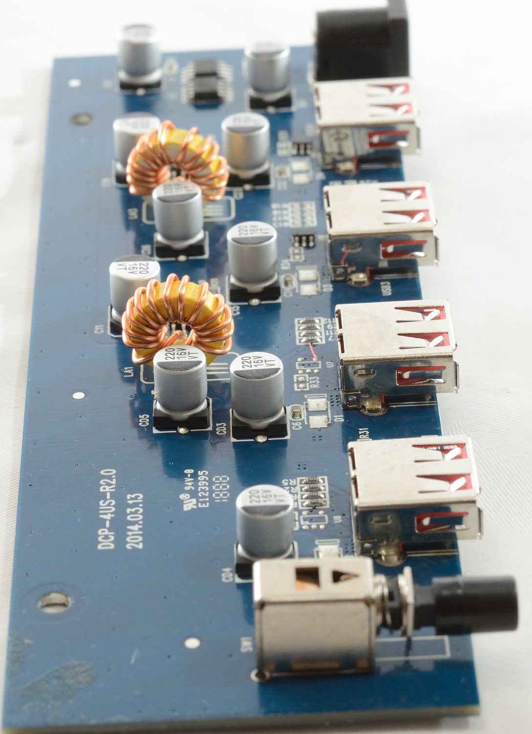
There is two switchers on the circuit board (U3, U4) that converts 12V to 5V, one of the switchers supplies the two 2A output and the other the two 1A output (It would have been smarter to let each switcher handle one 1A and one 2A output).
The automatic coding is handled by U9 and U10, for the 1A output are resistors (R1, R2, R4, R5 and R7, R9, R11, R12), but there is also space for automatic coding IC's.
The on/off switch does not directly handle the current, but control two mosfet's (U1, U2).
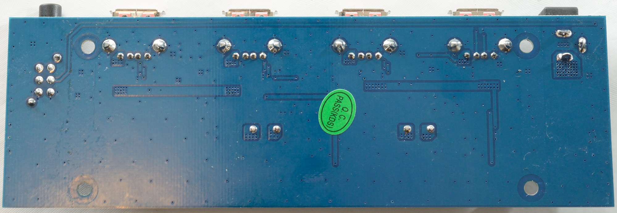
There is no part on the other side.
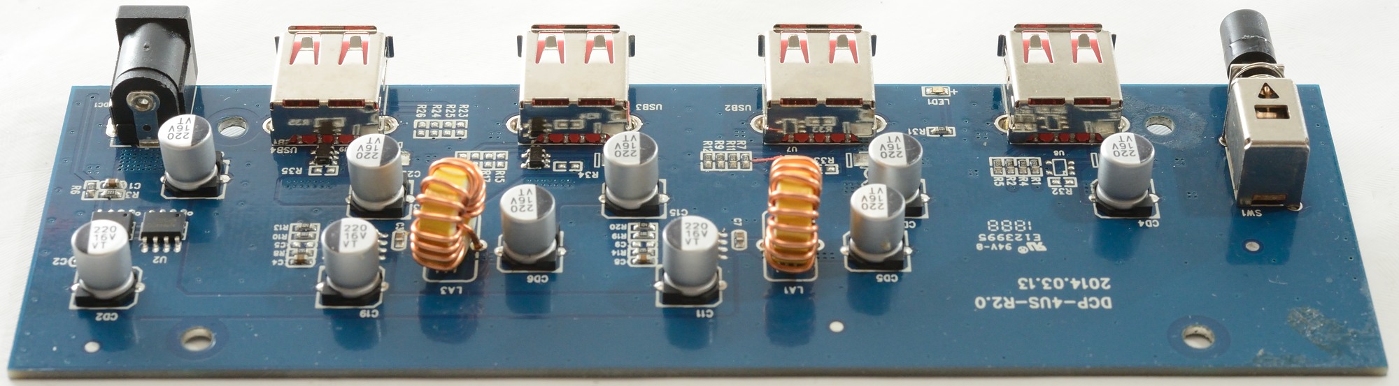

There is nothing with isolation distances inside this charger, because it uses an external 12V supply.
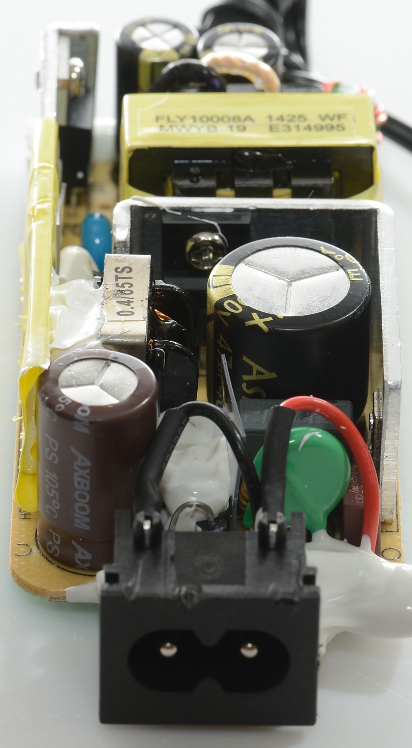
Tear down power supply
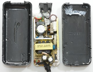
To open the power supply I needed my vice and a crowbar (a screwdriver), applying some pressure opened some cracks and a screwdriver could handle the rest. I would say this is a fairly good sealing.
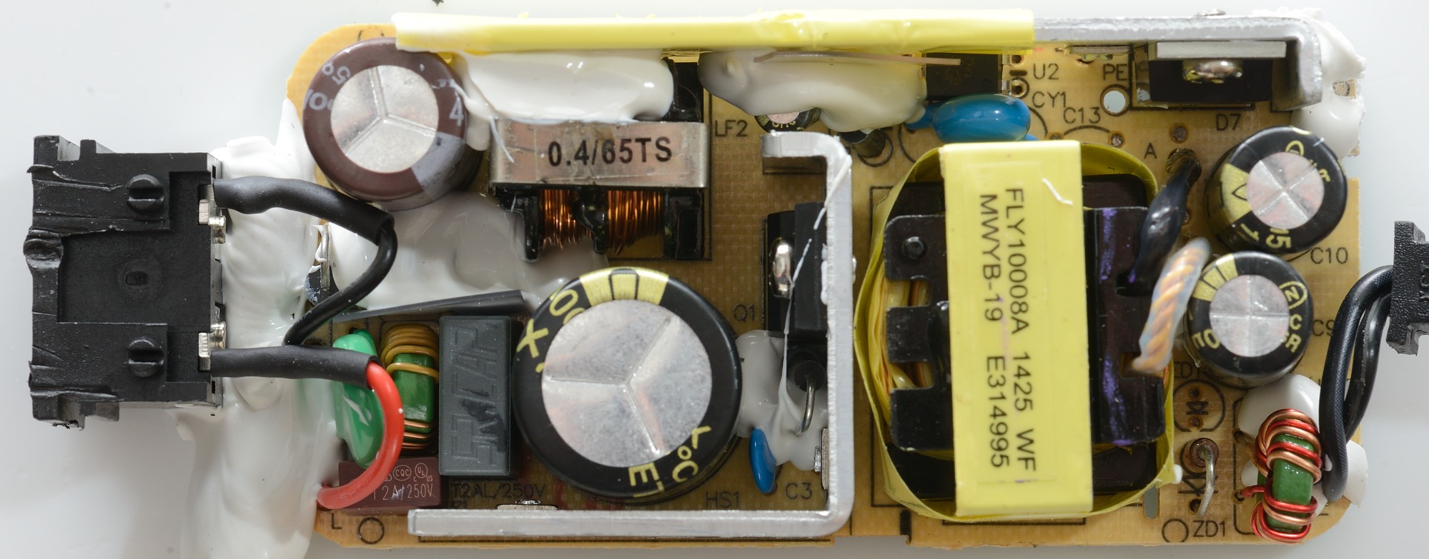
There is a lot in this supply. On the input you have a fuse (red) and a MOV (Green), two common mode coils. The bridge rectifier is four diodes hidden in the white stuff. On the heat sink is the mains switch transistor. There is also a safety capacitor (blue) and opto feedback.
On the low volt side there is the rectifier diode and a common mode coil.
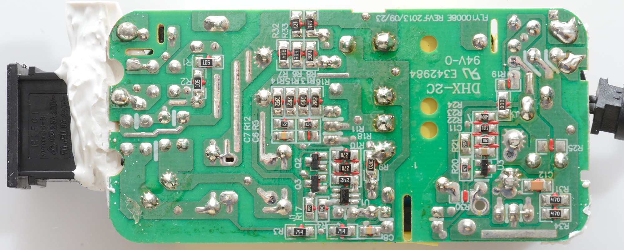
On this side there is not that much. There are a some resistors in parallel to handle more power.
There is the switch mode controller (U1) and the feedback controller (U3).

Here we can see the mains switcher heatsink and the output common mode coil.
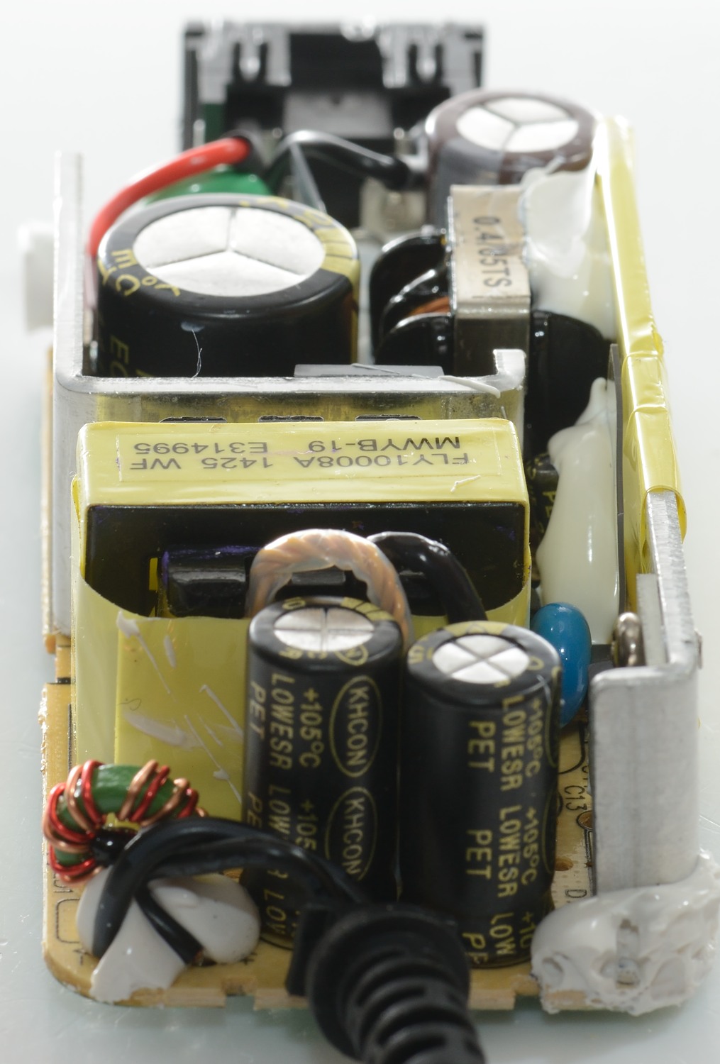
The green part is a MOV to handle voltage transient, this is not very common, but very useful in some locations.
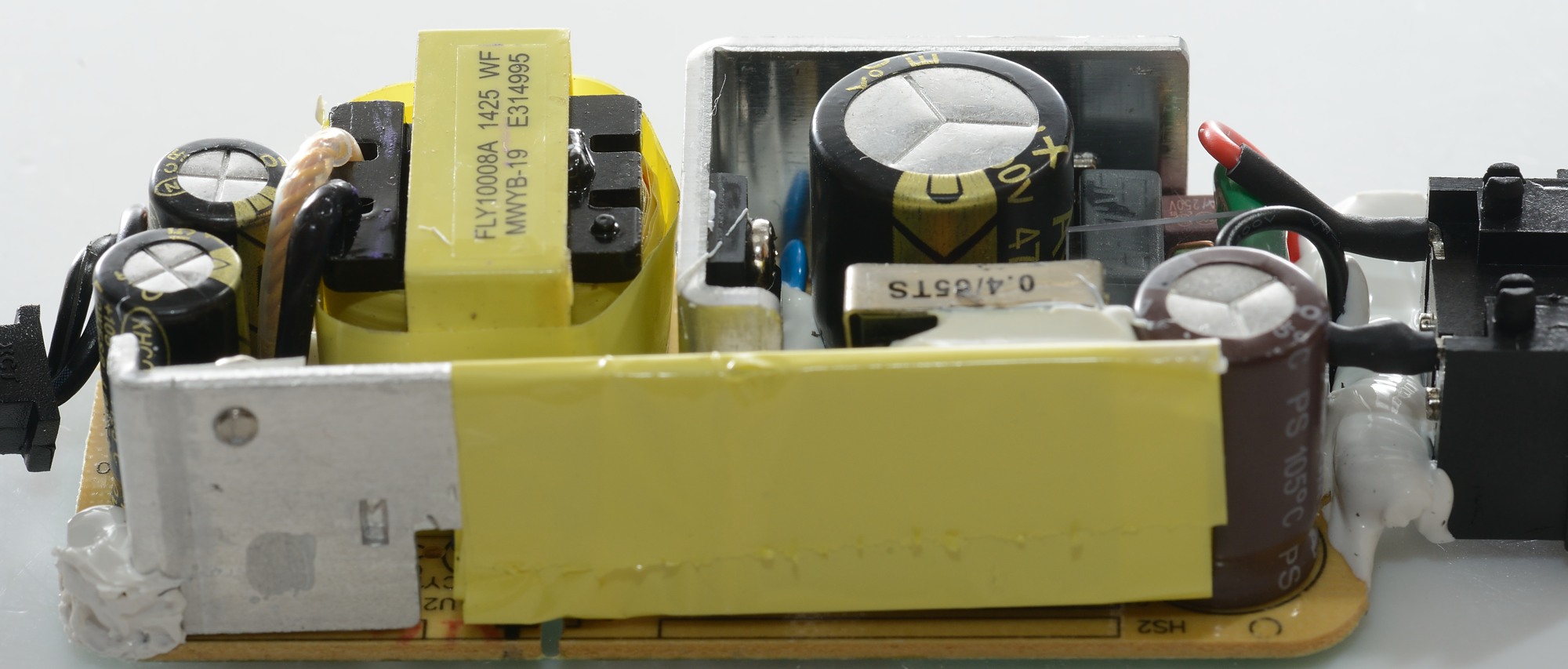
The heatsink for rectifier diode. It is wrapped in isolation tape for the part that is close to mains voltage.
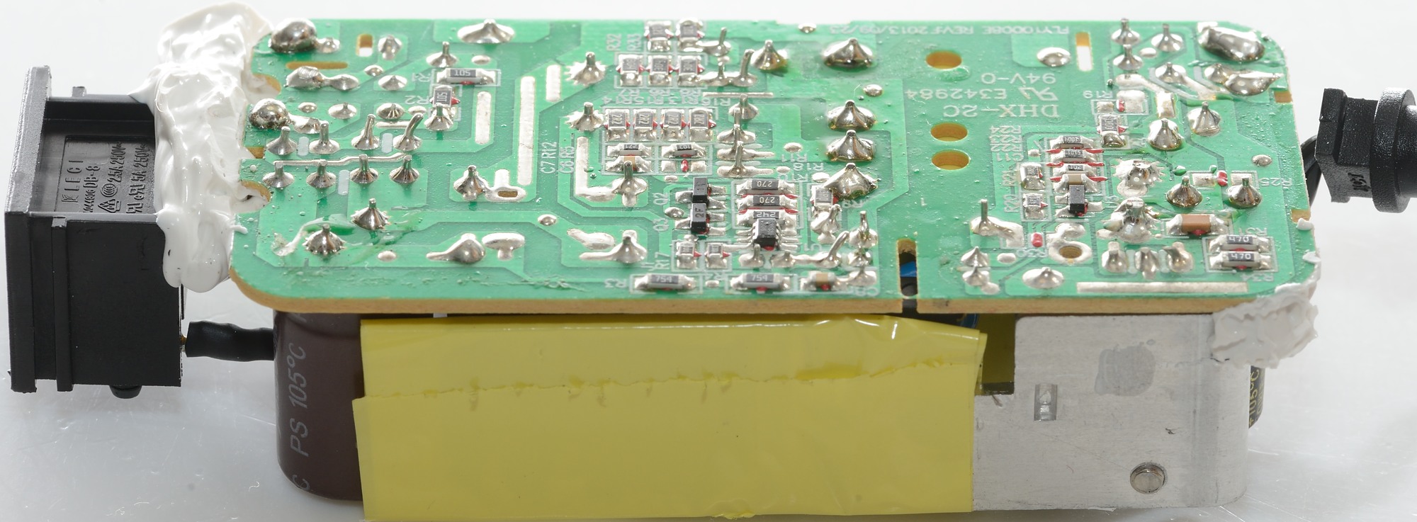
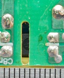
There is the required distance between mains and low volt side, the slot in the circuit board is not needed.
Testing with 2500 volt and 5000 volt between mains and low volt side, did not show any safety problems.
Conclusion
This is the largest usb charger I have tested to date and the first one with external power supply. It has some minor issues: Why not build the power supply into the unit and why load one channel with 2x1A and the other with 2x2A (Where it is struggling), using 1A+2A for each channel would have been much better. Coding as Apple 1A is silly today, Apple can handle DCP.
But if you like a dedicated place to charge your phones and pads it works very well, especially if you have at least on Apple phone, but even without it can handle two devices at fairly high speed.
Notes
The charger was supplied by Orico for review.
Index of all tested USB power supplies/chargers
Read more about how I test USB power supplies/charger