Recently there was a question as to if modding on BLF was dying off. I hope this thread will serve as proof that modding is alive and well.
Post your flashlight mods here, post your random other mods here. Post your big mods here, post your small mods here. If you don’t think it’s worth starting a new thread to show what you’ve done, post it here.
Discussions welcome and encouraged. Ask questions so you can do it too.
Let’s keep it alive just like the “What you got today” thread.
Hey PD, thanks for starting this thread. So many little things do not deserve a thread of their own, but this can be a repository for basic and quick mods for anyone looking for ideas.
I changed the XP-G2 in a TG06 to a 219C, could not stand the cold here in Illinois! Then, I took the pulled emitter and installed it in my best friends Guidesman to replace a really old XP something and gave him much more light! Now he wants me to order another XP-G2 for his other Guidesman 2*AA.
I also upgraded an Ultrafire C3-SS to an XP-G2 4C and really like the way it came out. It was a big step up from the XR-E that was in it.
I am actually having fun with the little project lights right now. Deciding what to do with a Supfire L3 and Uniquefire UF-2200.
Well, I put my BLF A6 back together. And it still worked. Not sure if that counts as a mod but I consider it a success. I also tried to open a few lights. Just to see what was in there. They still work.
I did some measuring on a headlamp I want to mod. I am still lost , but I am not giving up….
I have gotten stuff to do mods with. I have a table to mod on. I have the time to mod. My idea’s change every five seconds, no wait, every 10 seconds, um I mean they change every day. Yeah every day I change my mind.
List of lights I want to mod.
Rayfall HS1L headlamp. Emitter and driver.
Novatac Special Ops. Emitter and driver.
Novatac 120E. Emitter.
Also have some Idea’s I would like to make happen but don’t believe they have what I am looking for.
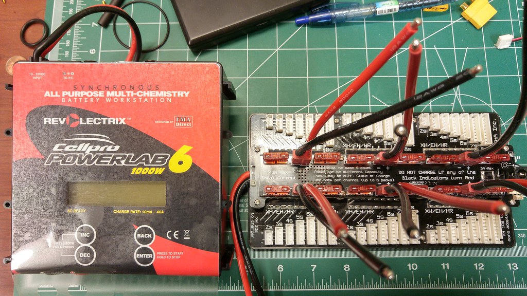
I’m working on converting a 1000w server power supply into a power supply for my newly arrived Powerlab 6. I’m mostly going to be using it for Lipo’s for my quadcopter(s?), but I have the data cable so perhaps Li-Ion testing may be in the cards at some point too. I’m delayed however by a lack of a server power supply power cable. One is on order now, and I should get it Thursday.
i received my boruit headlamps from gearbest black friday sale. might start a thread about them later on, if anyone’s interested.
one one of them i changed the xp-e to nichia 219a, changed one TIR-optic and put some frosted tape on both TIRs. On the other i put frosted tape on both sides of the main glass lens.
Nice thread-subject pd68, indeed I do mods that I do not bother making a thread about, but have nice enough ideas to report somewhere.
I modded one of these AA zoomies yesterday with a 6-chip AK-47-C1 and dedomed XP-E2 Torch. It lights up but everything went wrong, total failure, bad output. What went mainly wrong is that I sanded down the 17mm AK-47-C1 driver to 15mm (3 chips stacked for 2100mA) but not enough, pressed it in anyway with a vice and lots of force and then the aluminium of the pill was stretched out so that the pill did not srew in the batterytube anymore. Then I sanded the threads of the pill down to compensate for that but it still did not screw in, then I forced it in, ugly, ugly, ugly. On top of that in the end the current appeared just 1.2A, even on an Efest IMR 14500, and the light was even dimmer than that. I have another one of these flashlights, will do a proper mod on that one and report, it is a nice host, with some work it can become a great EDC :-)
After destroying the driver of a new xtar wk42 trying to change the LED and add a capacitor to reduce the effect of PWM, (the cap buzzed like crazy!!) * Insert ramble here * I tried a 4x nanjg that sucked and ended up putting in a LD-30 that ( insert more rambling and cussing here ) eventually worked!
Been under the weather lately, but I do have a Luckysun F3X on the way to the house. gonna see what I can do with the thing. the 1500 lumens it’s rated at seem very underpowered for 3 xml2’s. Who knows, may have a triple xhp-50 on my hands here soon!
Had one of THESE from Kaidomain and had to drill the driver to get the head unscrewed. Some threadlock and time on a radiator heater, plus the two holes in the driver finally allowed me to get into it.
Used the 3B XML2 on aluminum and the 6x7135 3+5 mode driver leftovers from one of my triple hosts to mod this into a little 16340 flooder…
Actually a nice in your sweat pants pocket light, though who knows how long the switch will last at 2A. Fun spare parts build from what I thought would be a good host for $6.