Recently I received my first ATtiny25V based BLF X5/X6 driver from banggood. But - the mcu is labeled “Atmel Tiny25 20-ssu” which says it’s NOT the low volt ATtiny25V. Minimum voltage of the used mcu is 2.7 volts, much more compared to the V version with 1.8 volts.
Should we expect some weird behaviour in low batt situations?
uh, oh. Can you see the part in the sales page picture well enough to identify it?
It’s clear from the link what they claim to be selling:
Here’s the other one: ATTINY25-20SSU Atmel, ATTINY25-20SSU Datasheet
Where do you look for the marking?
I am currently writing and testing new driver firmware for this device and the older A17DD with ATtiny13a. Before hooking up the programming clip I checked the mcu with my handy microscope, since pcb’s are the same and you may brick the mcu’s when setting the fuse bits meant for another mcu.
So I am sure about the label, would be interesting to know what they built into the X5/X6 flashlight.
What do we look for and where (and at what magnification)?
The USB microscopes are getting cheap lately, and the old Q3 “toy” USB microscope has a decent 10/60/200x lens
I am using this one, it’s great:
A magnifying glass is also ok.
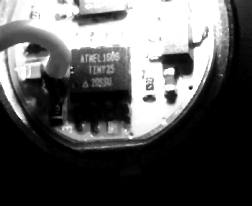
The mcu is the chip with 8 legs, the label is printed on top.
Found a picture of one X5/X6 flashlight driver here:
NOT the ATtiny25V either.
Don’t know the exact voltage drop over the schottky diode, may be about 0.3 volts, so we may expect problems already at 3 volts battery voltage. Probably some mcu’s will also work a bit below their specified minimum voltage but I would rather like to have some safety clearance.
OK, the driver I had in the mail arrived today.
The chip is the ATMEL 1609 TINY25 20SSU
So, anyone else looked?
Did this chip get substituted during the original group buy?
(I recall mention that something was substituted, but I don’t recall anyone ever saying exactly what)
Or is this one used only since the light went retail?
And how do we test to see what difference it makes at low voltage?
As always with QC — QC has to check every single item, every single time, and not using checkmarks or strikethroughs on a list — initials and date.
But we knew that.
BangGood item question page is: http://forum.banggood.com/forum-topic-169312.html
!
!
Very interesting find. I just checked a couple of my older sample drivers and they too have the 20SSu ATTiny25, even one I built does, so I checked my stock from Mouser and wouldn’t you know it, I bought the 20SSU without realizing the difference! Heading to look at the spec sheets now, perhaps that is a key to some of the sensitivity issues…
How to get rid of strobe on the kronos x5?
I haven’t been following the X5/X6 thread very closely, has the chip substitution caused any notable problems? What are the sensitivity issues?
Mike only told us about this early this morning, remember:
Thu, 05/12/2016 - 10:07
Thank you Mike.
Now we have two more data points, mine and DB C’s.
Going forward, it’s something to watch for.
Looking back, and looking at what’s currently advertised for sale — time will tell.
I know nothing about any of the electronics so I’m done. I trust the folks here who know stuff to work it out and educate the rest of us.
It’ll take time.
The spec sheet’s do indeed call for the 20SSU to have a range of 2.8V to 5.5V. The 10SSU is rated at 1.8V to 5.5V. What that might mean to how the light actually functions is not within my capabilities but I’ve posed the question to some that might know.
Sensitivity that I’ve seen is some Bistro drivers do not want to work at high load levels or high current draw. They bump back down to moon. And these invariably will not allow a tail cap current test beyond level 4, maybe 5. Full Turbo wont’ measure, it just bumps down to moon. I don’t know exactly why, and it’s done it even on some of my own builds from scratch on OSHPark boards with premium components.
Digging…
ToyKeeper tells me “the trailing edge of a FET pulse was actually creating an over-voltage condition for a moment, causing the MCU to reset. It wasn’t an under-voltage thing. A different FET can fix it, or an added resistor, or a bigger C1.”
She also said she’s tested the 2.7V variant down to 2.68V with no issues and believes the LVP is set at 2.9V from Manker. This shouldn’t be an issue but she agree’s that the 10SSU might be a better overall choice. I’m trying to determine what resistor value and where, but have used higher cap values at C1 to no avail on a couple of my own builds and on one troublesome sample driver from Manker.
Will let y’all know as I find out…
The Schottky diode eats up to 0.3 volts, so 2.9 volt as switch off limit seems still to low.
So the precautionary question — what’s the worst that could happen?
Is this — a known substitution not worth mentioning as it makes no practical difference, or
— an undisclosed modification that y’all didn’t know happened and now want to understand? Or
— a surprise to find in production drivers, but you already know isn’t a big deal for us end user type people?
I wondered when I read
but that possible worry was raised a year ago with no further mention I can see — long since an old question. Not to worry?
People often bring up that the 10SSU (attiny25v) is 1.8-5.5v but miss the fact that atmel says you need to use 4Mhz max for the 1.8-2.7v range. And none of the current firmwares implement 4Mhz. (4Mhz code)
Aka: the minimum voltage is 2.7v (with the current firmwares) regardless of whether you use attiny25 or attiny25v.
The ATtiny13a runs with 4.8 Mhz and is fast enough for everything, so I don’t see any problem running the 25V with 4 Mhz.
I would like to do some tests with this mcu’s but unfortunately I have only 25_V_ for my breadboard and no 25_V_ in the small package for the driver PCB. Will order some today. Never desoldered this small things, what’s the cleanest and cheapest way to change the mcu on the PCB? I don’t mind if the desoldered one get’s destroyed.
I really wouldn`t be astonished if the problems with the X5/X6 disappear with the right driver and frequency.
I suspect using 4Mhz may very well improve reliability of even the attiny25.
And that means 3 volts from the battery because of the power drop at the schottky diode. At 2.7 volts from the battery the mcu will be at 2.4 volts!
The fuse settings I found in Toykeeper’s bistro code indicate a brown-out detection at 1.8 volts.
Hi,
did you test a MTN 17DDm Driver with Bistro UI under high loads already? I plan using that one with some triples. Now i am confused if the driver will work with high currents.
Regards
Kenjii