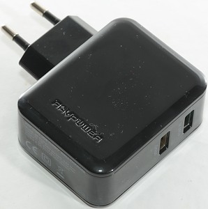
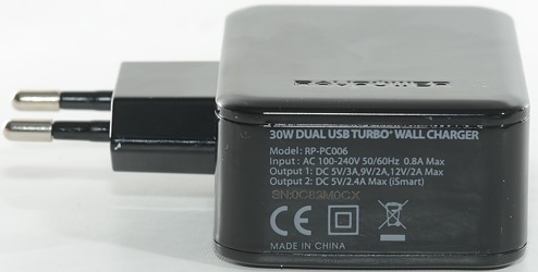
Ravpower 30W Dual SUB Turbo+ wall charger RP-PC006
Official specifications:
-
QUALCOMM QUICK CHARGE 3.0: The world’s fastest USB charging technology provides up to 4x faster speeds - charge compatible devices from 0% to 80% in just 35 minutes.
-
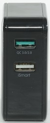
DUAL USE: QC 3.0 port charges at a powerful 12V/2A and also provides 5V/2.4A output for non-QC devices - dual port design lets you charge 2x normal devices (iPad, iPad, etc.) at the same time for 4.8A total output.
-
SMART: Includes RAVPower’s exclusive iSmart charging technology plus QC 3.0 INOV (Intelligent Negotiation for Optimum Voltage) for maximum efficiency charging.
-
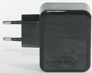
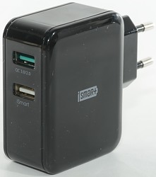
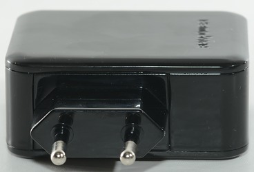
CONVENIENT: Small and travel-friendly charger with 100-240V universal power supply and foldable pins.
-
SAFE: Durable casing with over-heating, high-current, and voltage-surge protection for 100% safe charging.
-
Input: 110-240VAC
-
Output 1: DC 5V/3A, 9V/2A, 12V/2A
-
Output 2: DC 5V 2.4A max (iSmart)
-
Dimensions: 2.1 x 2.1 x 1.1 in / 53 x 53 x 27 mm (Wrong, see below)
-
Weight: 3.41oz / 96.9g
I got it from Ravpower
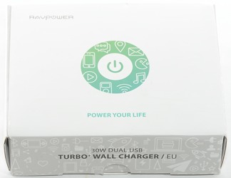
Ravpower uses a white cardboard box with very few specifications on.
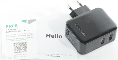
The box contained the charger, instruction sheet and warranty card.
Measurements
-
Power consumption when idle is 0.3 watt
-
Lowest QC3 voltage is 3.63V
-
iSmart output is auto coded with up to Apple 2.4A
-
QC output is QC only.
-
The charger has a blue led inside that is shining out through the usb connectors.
-
Dimensions: 65.5 x 88 x 28.2 mm
-
Weight: 103.9g
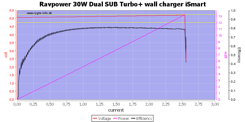
This charger has a very good output profile, it will compensate a bit for cable looses (Voltage increases with load) and it has overcurrent protection at about 2.5A on the iSmart output.
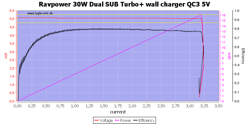
Quickcharge is supposed to deliver up to 3A at 5 volt and it does, with a overcurrent protection at about 3.2A (Very good).
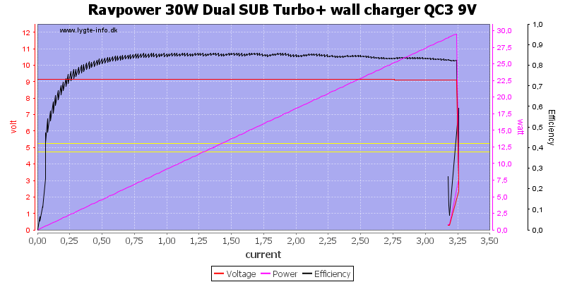
At 9V the current is supposed to be down to 2A, but the charger can still deliver 3A.
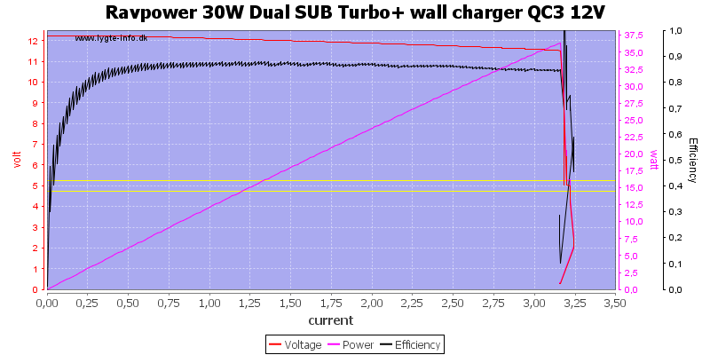
The 3A is also aviable at 12V.
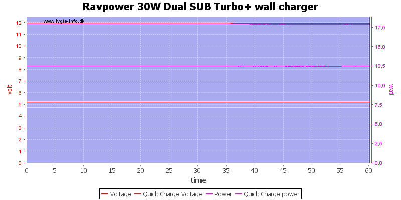
Loading both QC and iSmart output for 1 hour works fine (I only loaded 12V with 1.5A, because that is the usual QC limit).
The temperature photos below (Except the inside photos) are taken between 30 minutes and 60 minutes into the one hour test.
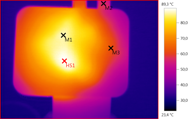
M1: 86,7°C, M2: 56,0°C, M3: 62,1°C, HS1: 89,3°C
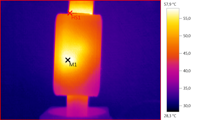
M1: 57,1°C, HS1: 57,9°C
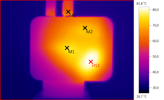
M1: 74,8°C, M2: 71,6°C, M3: 61,2°C, HS1: 81,8°C
HS1 is the transformer, M2 is the two QC diodes.
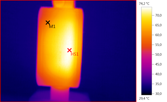
M1: 59,8°C, HS1: 74,2°C
HS1 is the rectification transistor and circuit board.
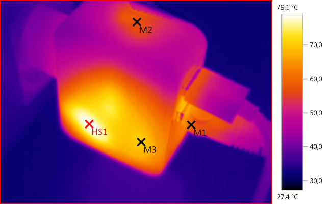
M1: 59,9°C, M2: 57,0°C, M3: 70,5°C, HS1: 79,1°C
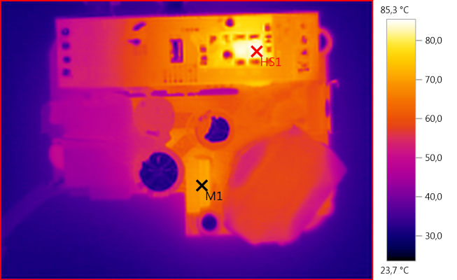
M1: 70,4°C, HS1: 85,3°C
HS1 is the two QC diodes.
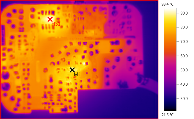
M1: 89,1°C, HS1: 93,4°C
HS1 is the iSmart buck converter chip.
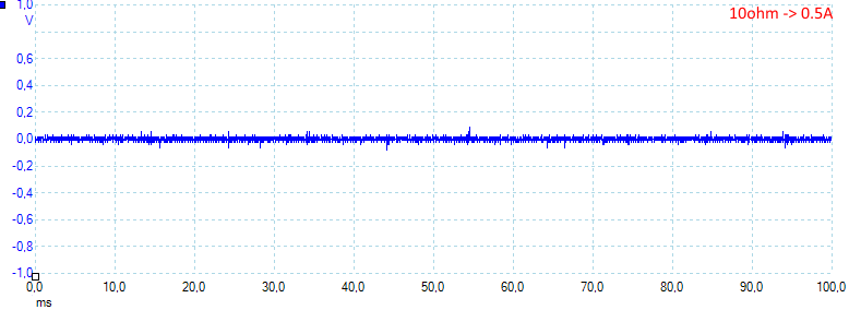
At 0.5A the noise is 14mV rms and 200mVpp
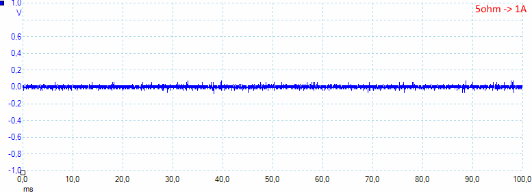
At 1A the noise is 15mV rms and 160mVpp
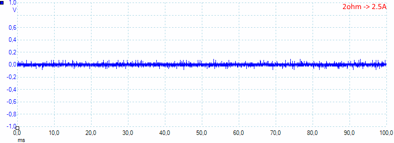
At 2.5A the noise is 19mV rms and 255mVpp
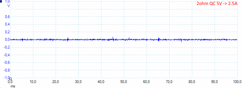
At 5V and 2.5A on QuickCharge the noise is 5mV rms and 110mVpp
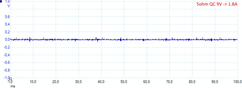
At 9V and 1.8A on QuickCharge the noise is 6mV rms and 125mVpp
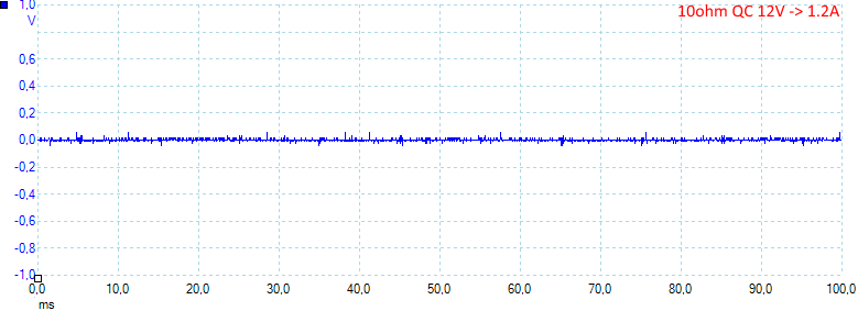
At 12V and 1.2A on QuickCharge the noise is 5mV rms and 117mVpp
Tear down
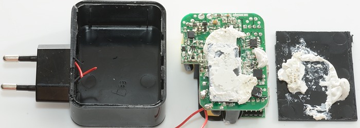
I could not break the glue with a vice or mallet, I had to cut it open, with the square shape it was fairly easy.
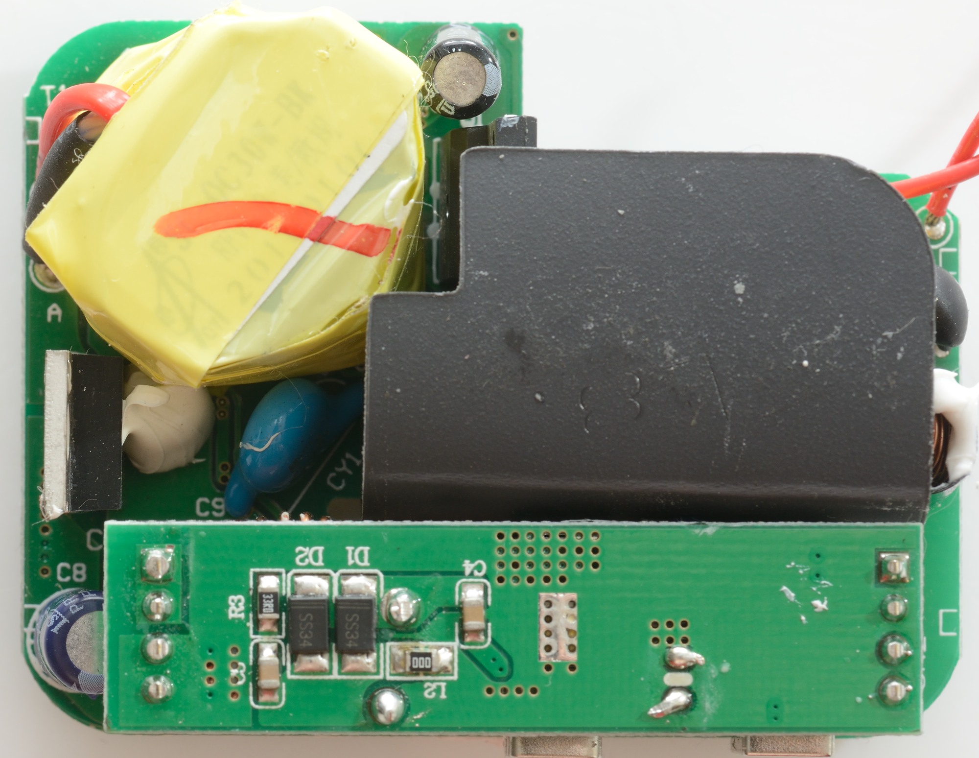
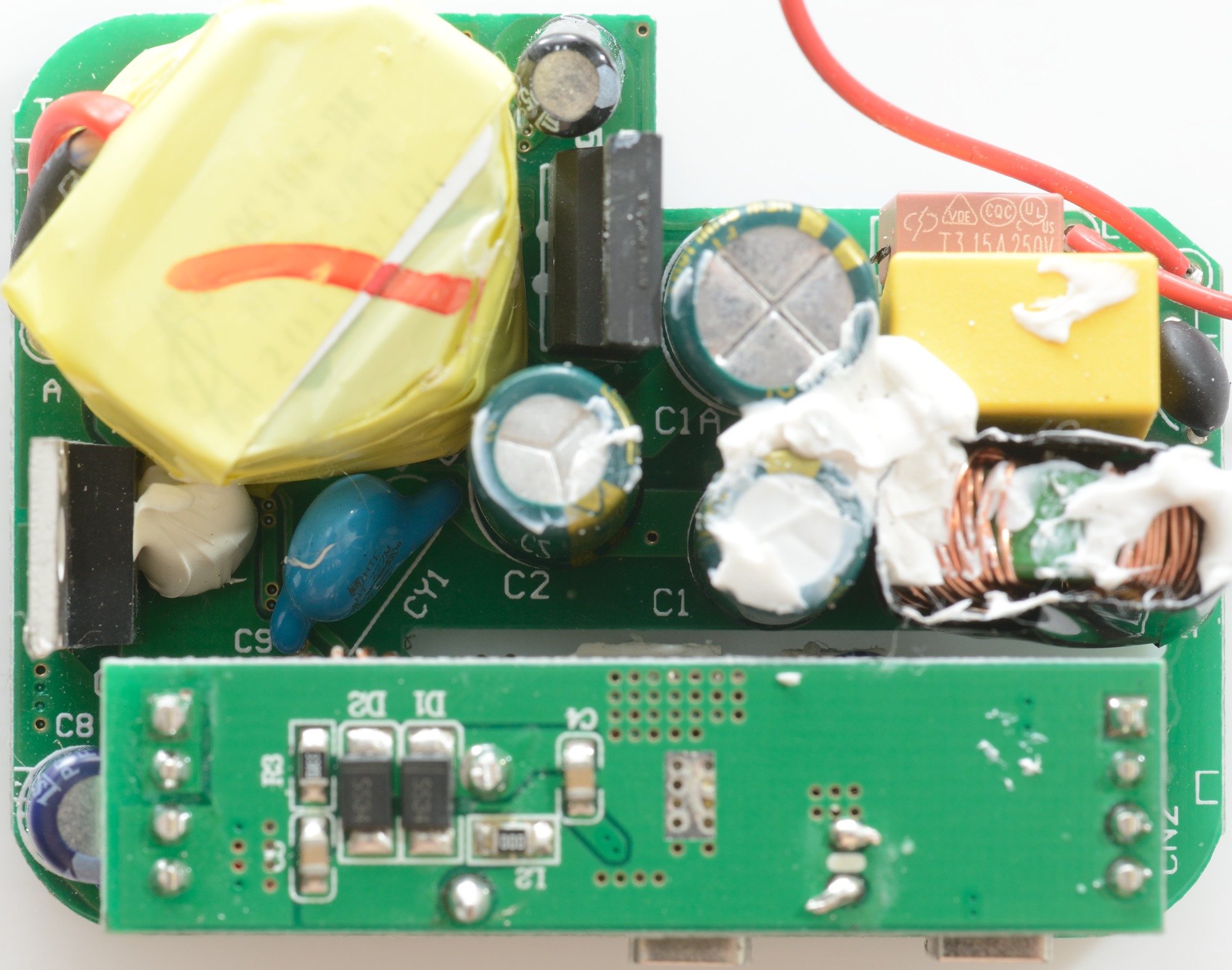
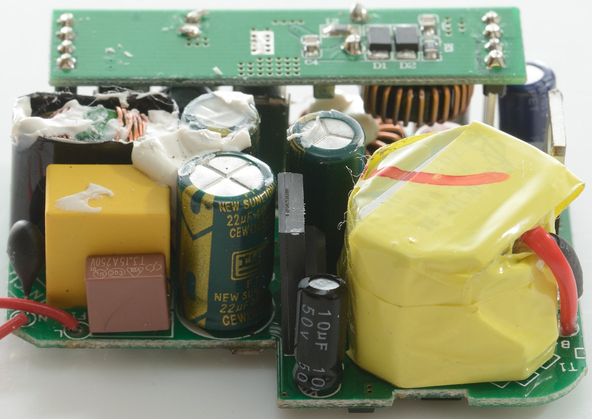
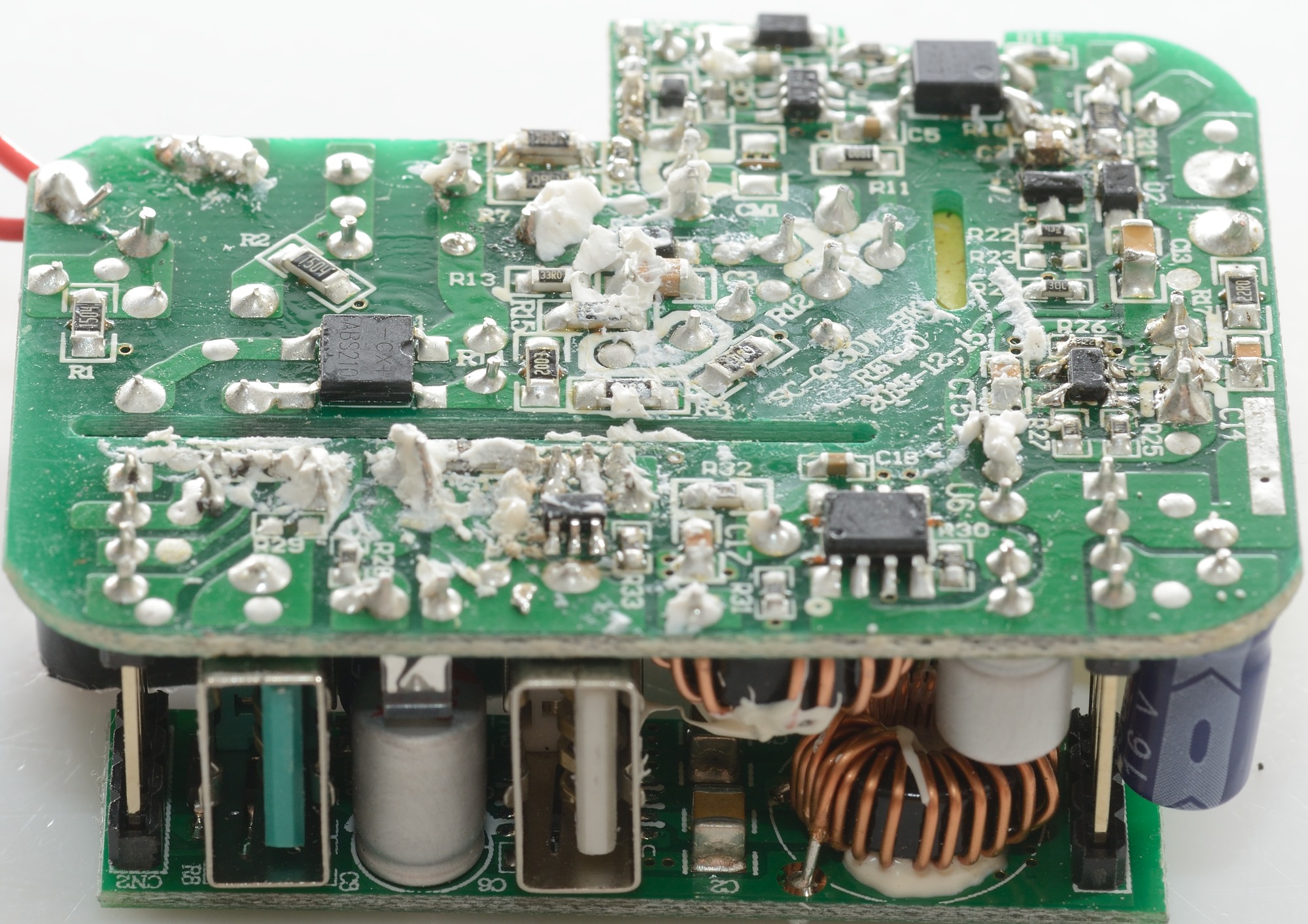
The mains part is covered in isolation paper. When it is removed a red fuse, a black inrush current limiter, a common mode coil and the mains switcher transistor can be seen. There is also a blue safety capacitor and a rectifier transistor.
The small elevated circuit board will be covered later.
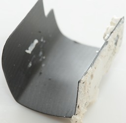
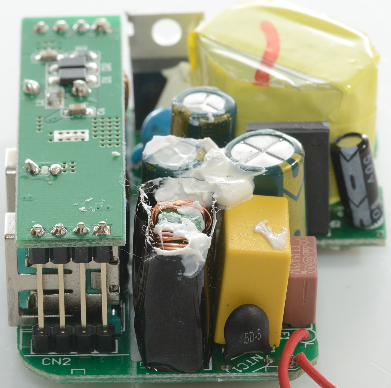
Here is the large piece of isolation paper that separates usb connectors from mains.
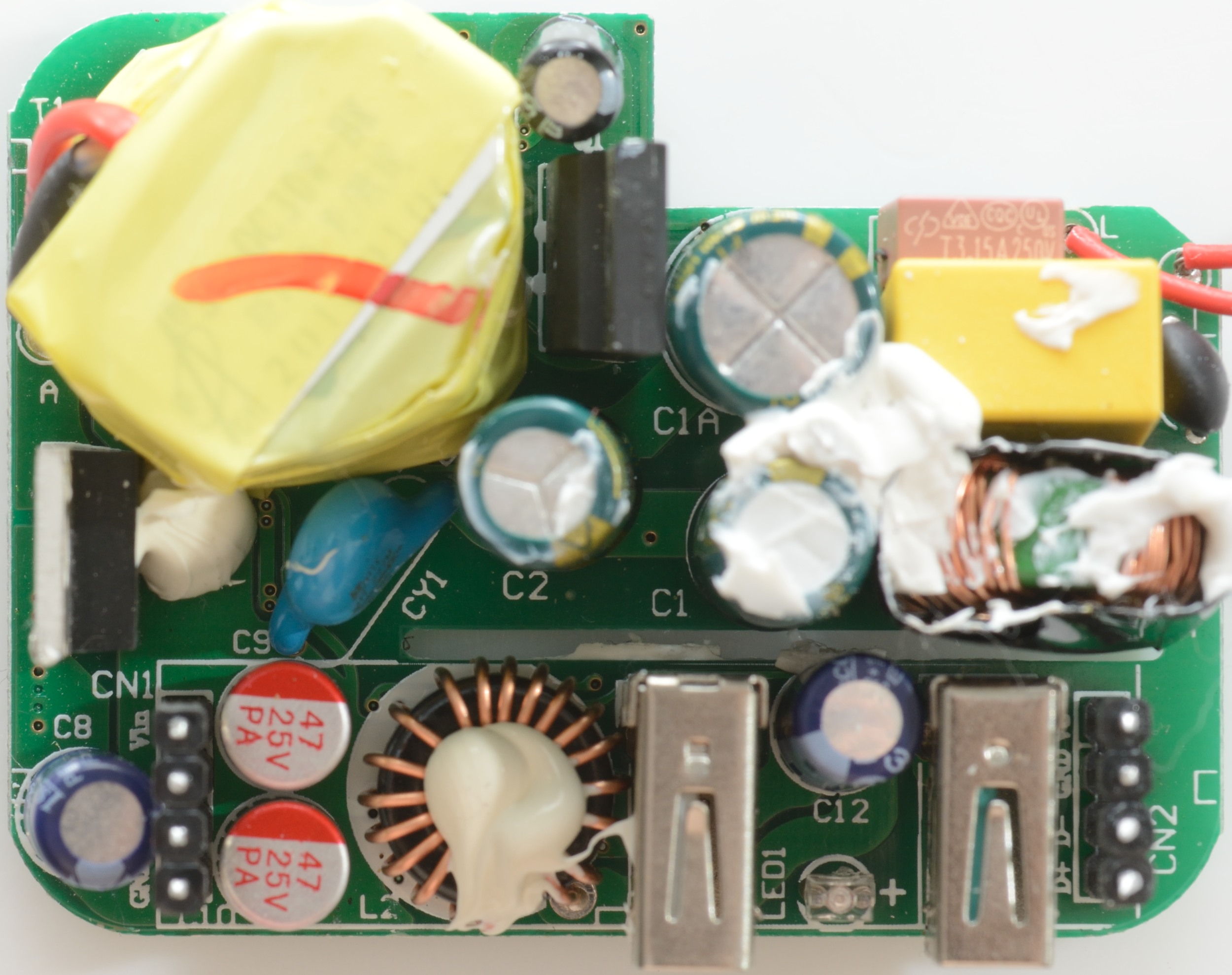
With the small circuit board removed another inductor can be seen and a blue led between the usb connectors. Notice the capacitors are 25V
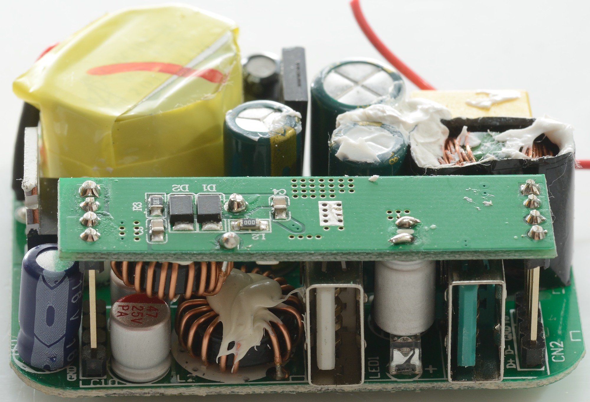
On the first picture the inductors for the two buck regulators can be seen and the led between the usb connectors.
On the second picture the inrush current limiter (NTC1) and the red fuse can be seen.
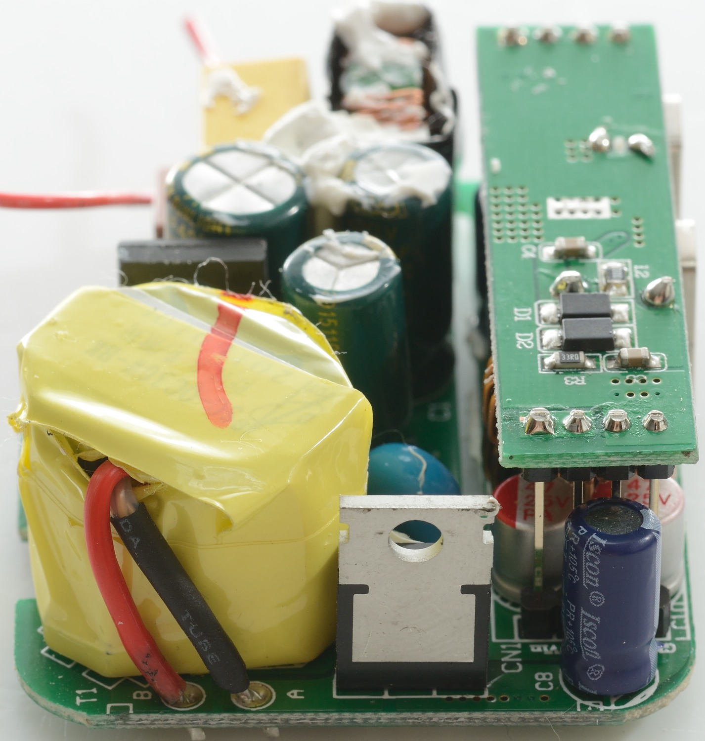
The mains transformer has one output winding that goes to the rectifier transistor. This rectifiers to 14.1V unloaded on the capacitors.
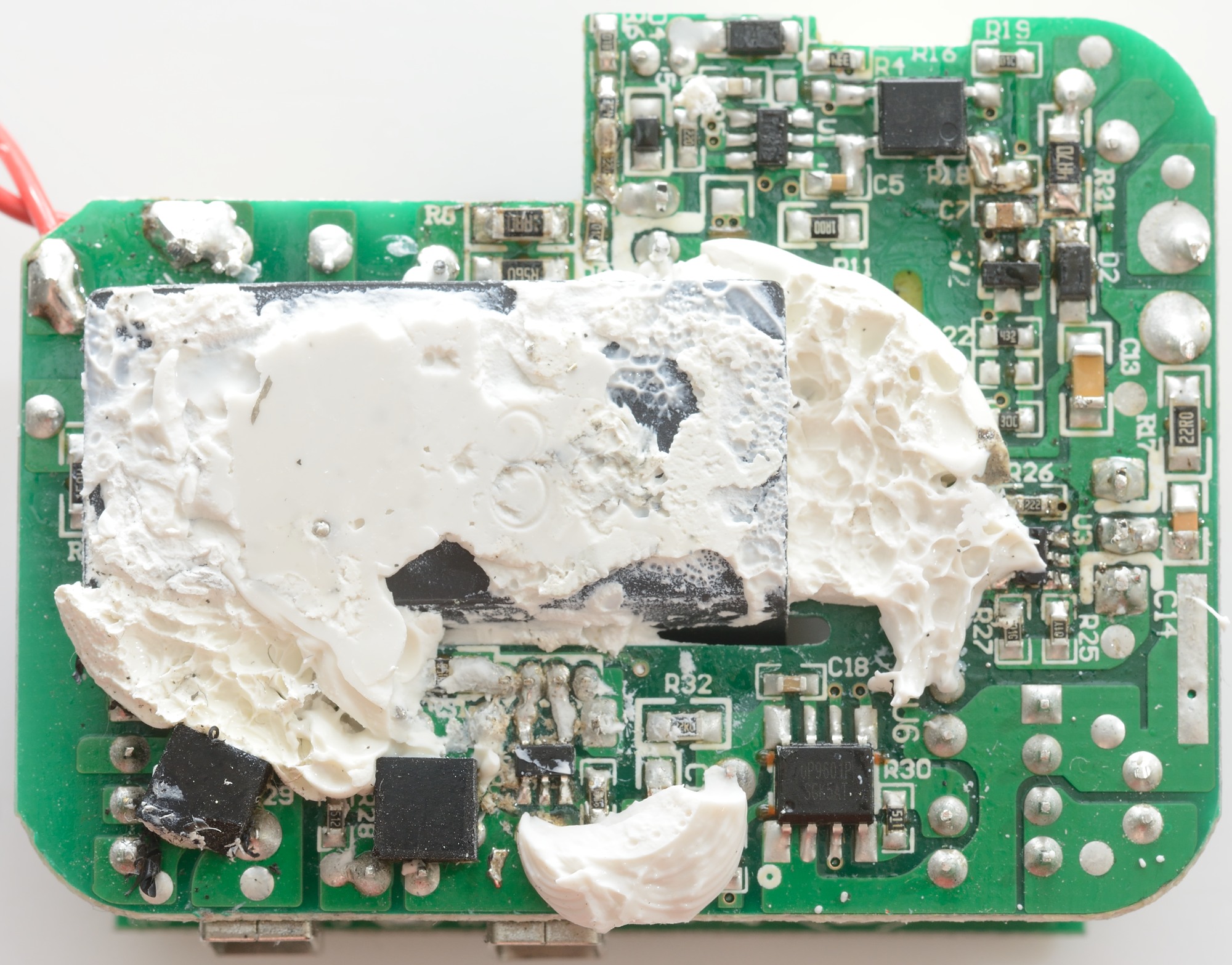
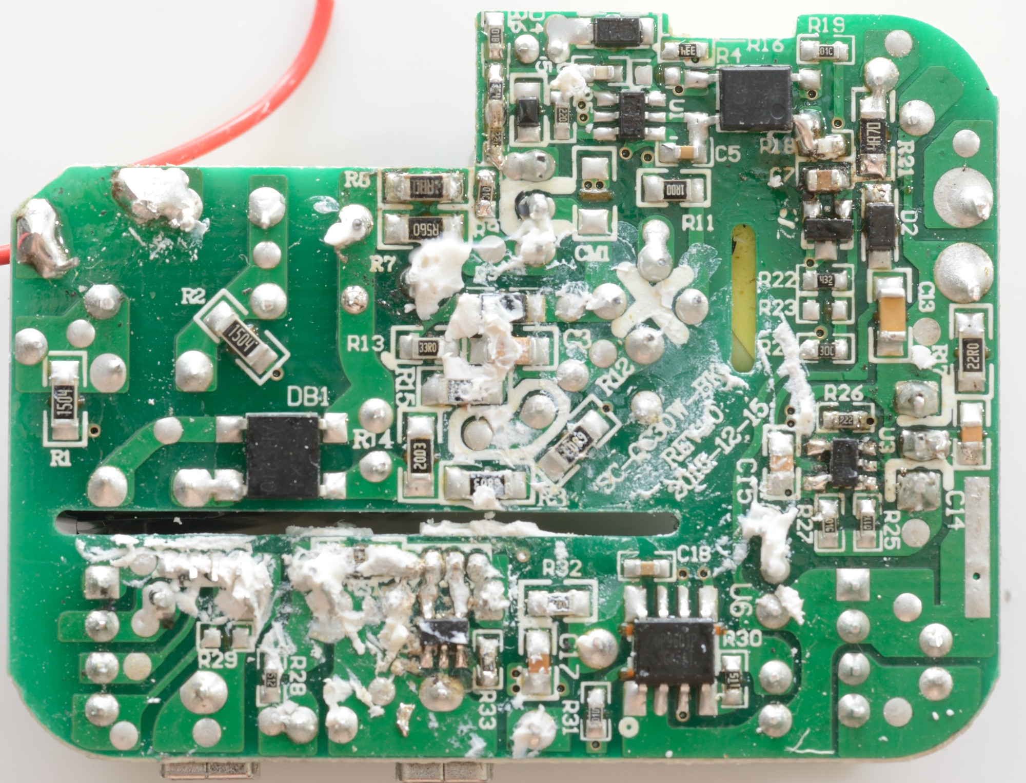
The paper also covers the mains part of the circuit on this side of the circuit board.
There is a bridge rectifier (DB1), a mains switcher controller (U1) with the opto coupler next to it (A 357 type). The part next to D2 is probably the voltage reference.
U3 is a synchronous rectifier controller (MP6901).
U6 is the switcher for the iSmart output, this chip must include a synchronous rectifier, because I cannot see any diodes. The 5 pin chip next to U6 is the iSmart auto coding ship.

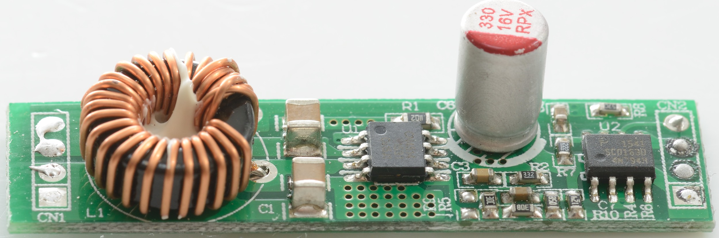
This circuit board handles the QuickCharge function, it is supplied with about 14 volt at CN1 and CN2 is connected to the QC output.
U1 (CN4514) is a buck regulator and U2 (SC0163D) is the QC3 controller.

The buck regulator uses two diodes in parallel.
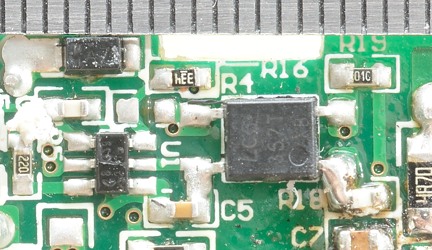
It looks like the safety distance is slightly on the low side.
Testing with 2500 volt and 5000 volt between mains and low volt side, did not show any safety problems.
Conclusion
This charger looks very good, it is able to deliver rated current, has very low noise and has proper over current protection on both outputs.
I will rate this charger as very good.
Notes
The usb charger was supplied by Ravpower for a review.
The Ravpower website has an artistic rendering on how this charger looks inside, it do not match my teardown, but some of it is correct.
Read more about how I test USB power supplies/charger