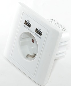
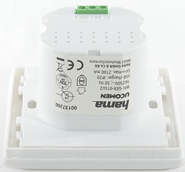
Hama Flush socket with two USB ports
Official specifications:
-
Input: 230VAC 50Hz
-
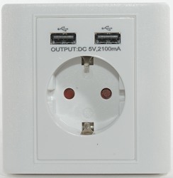
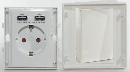
Output usb voltage: 5V DC
-
Output usb current: 1x max 2100mA or 2x max 1050mA
-
Mains output: Schuko
-
Wall socket depth min 47mm, ideally 61mA.
-
Connection leads: rigid 1.5 to 2.5 mm2
I got it from amazon.de dealer Telehomeshopping24
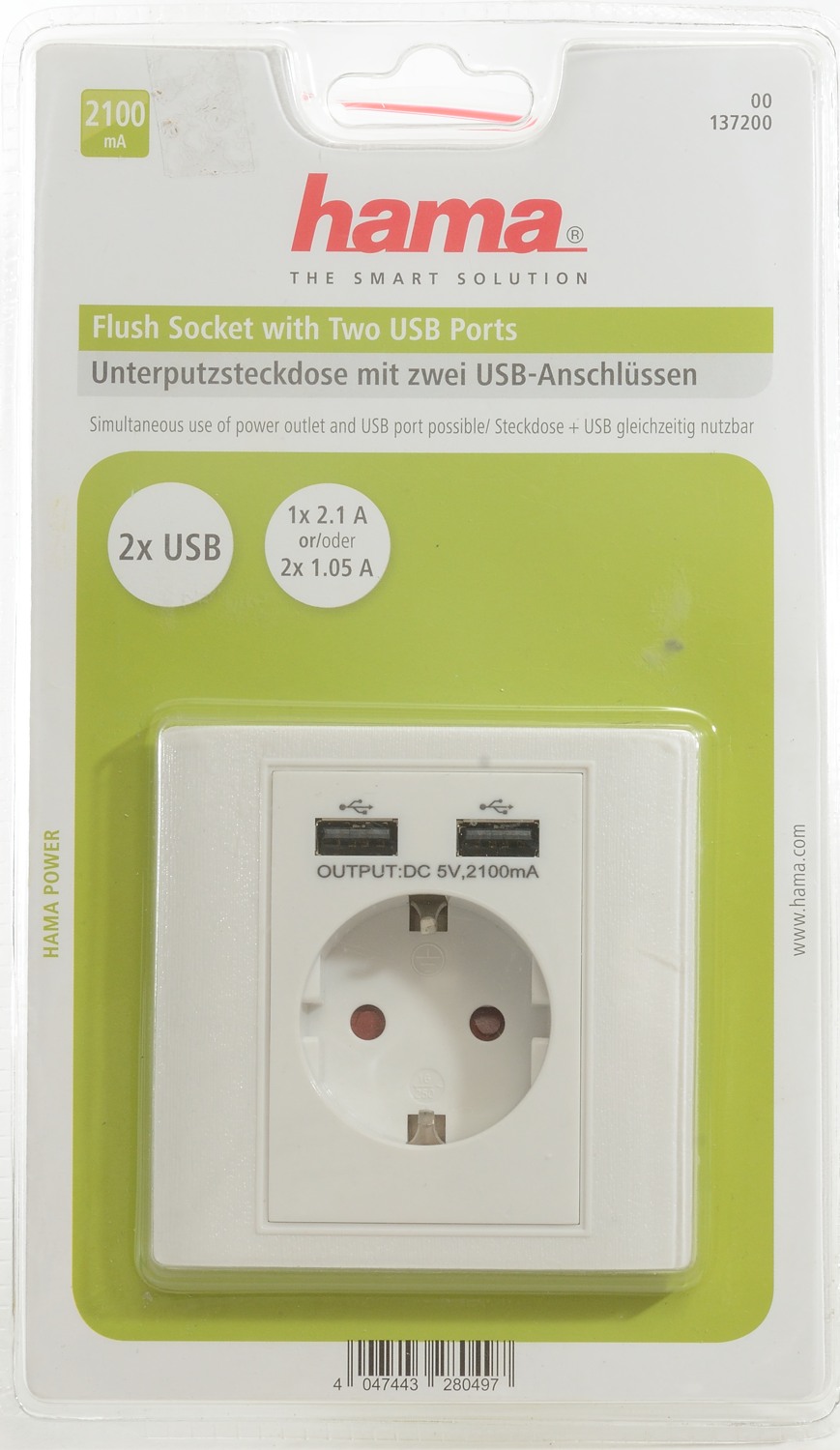

I got it in a blister pack.
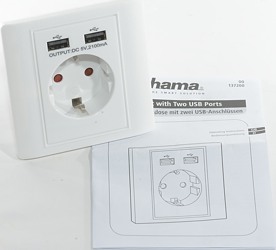
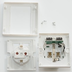
It contained the socket and a instruction sheet.
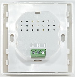
Mains wired are screwed on from the backside.
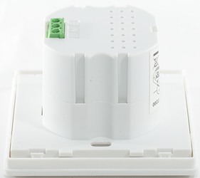
The frontplace is clipped on and removing it gives access to the mounting screws, but not anything carrying mains voltage.
Measurements
-
Power consumption when idle is 0.1 watt
-
USB outputs are coded as usb charger (DCP)
-
Both outputs are in parallel.
-
Earth is not connected to usb shield
-
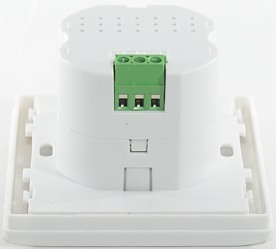
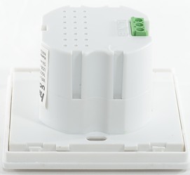
Need 43mm deep hole.
-
Extend 12mm out.
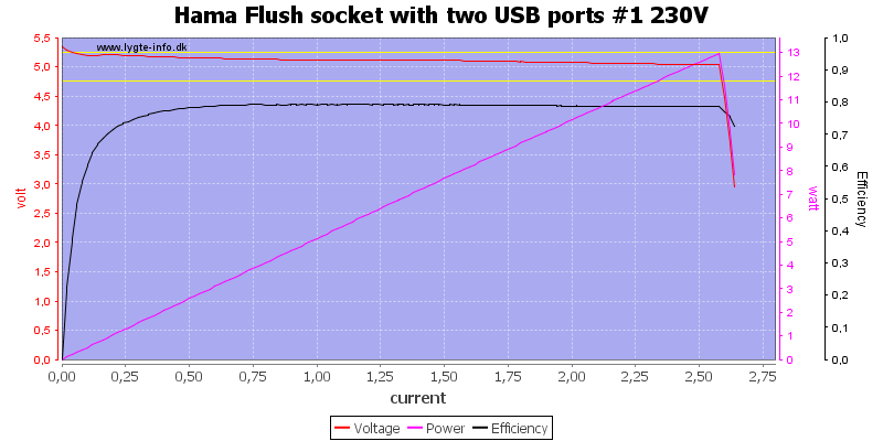
It can deliver 2.6A on port \#1.

And also on port \#2
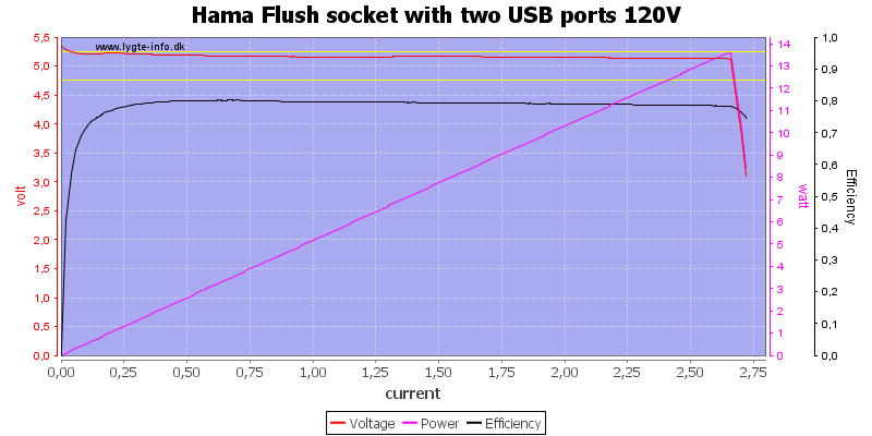
When running both usb ports in parallel the current is still 2.6A, here done at 120VAC
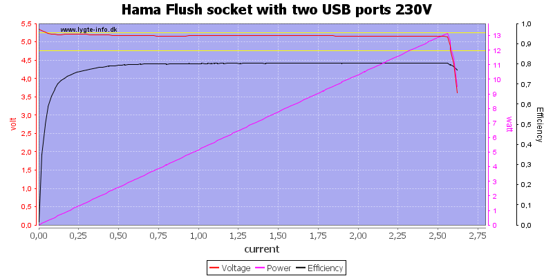
And at 230VAC.
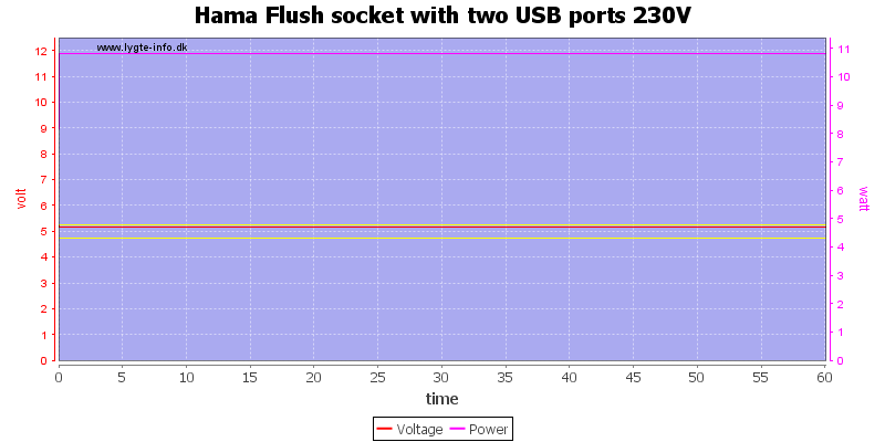
Running at rated output for one hour is no problem.
The temperature photos below are taken between 30 minutes and 60 minutes into the one hour test.
When mounted in a wall the temperature will depend on how the wall transfer heat.
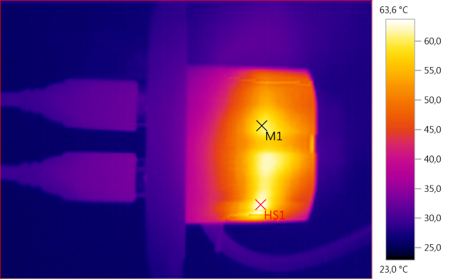
M1: 60,0°C, HS1: 63,6°C
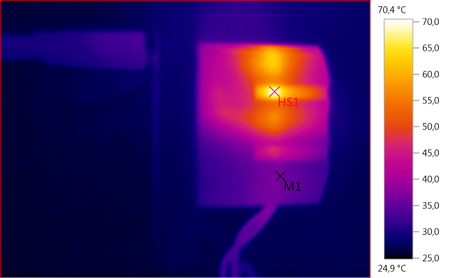
M1: 36,4°C, HS1: 70,4°C
HS1 is the rectifier diode.
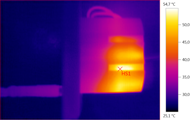
HS1: 54,7°C
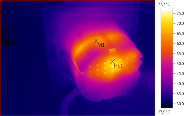
M1: 63,0°C, HS1 77,7°C
Here HS1 is the transformer.
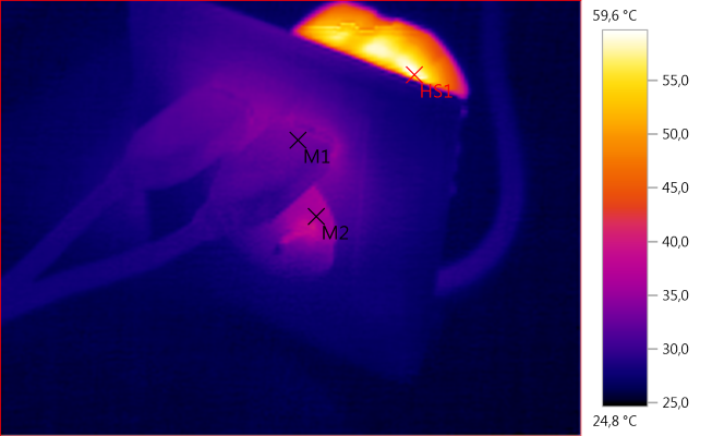
M1: 32,8°C, M2: 35,8°C, HS1: 59,6°C
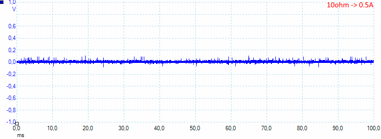
At 0.5A the noise is 15mV rms and 198mVpp.
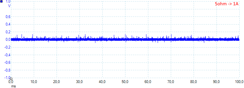
At 1A the noise is 25mV rms and 268mVpp.
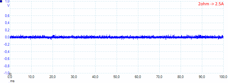
At 1A the noise is 22mV rms and 157mVpp.
Tear down
When the front frame is unclipped it is possible to unscrew more of the front and gain access to the usb connectors and a couple of clips.
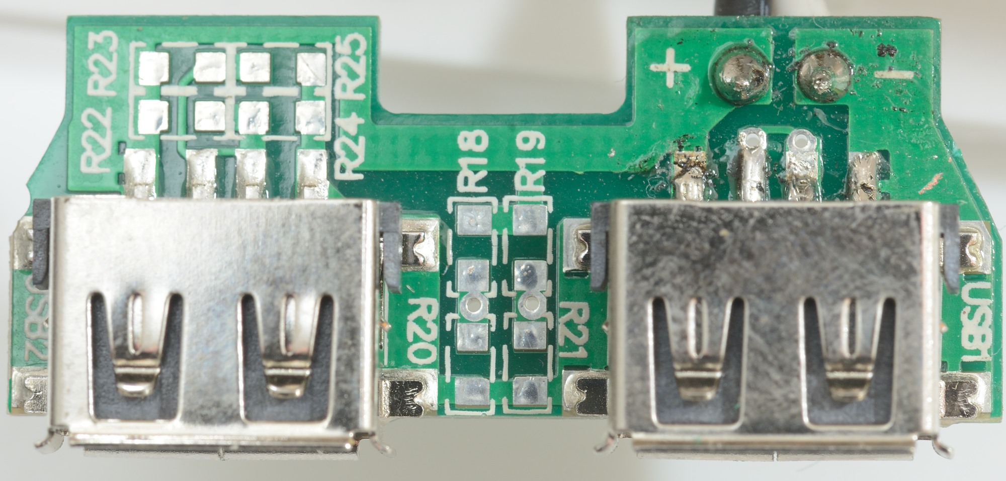
The usb circuit board is only the two connectors and space for coding resistors. These coding resistors are not used, the data pins are shorted on the circuit board for a DCP coding.

Not much here.
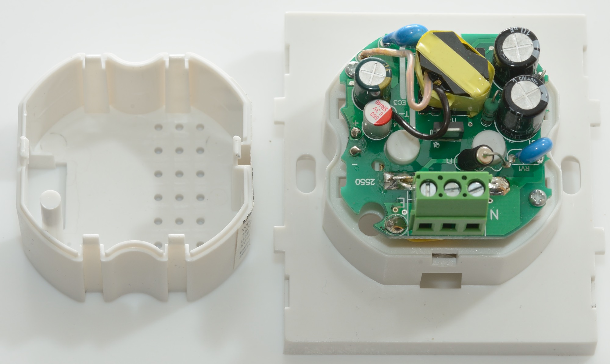
Unclipping 6 clips and cutting a label made it possible to remvoe the back cover.
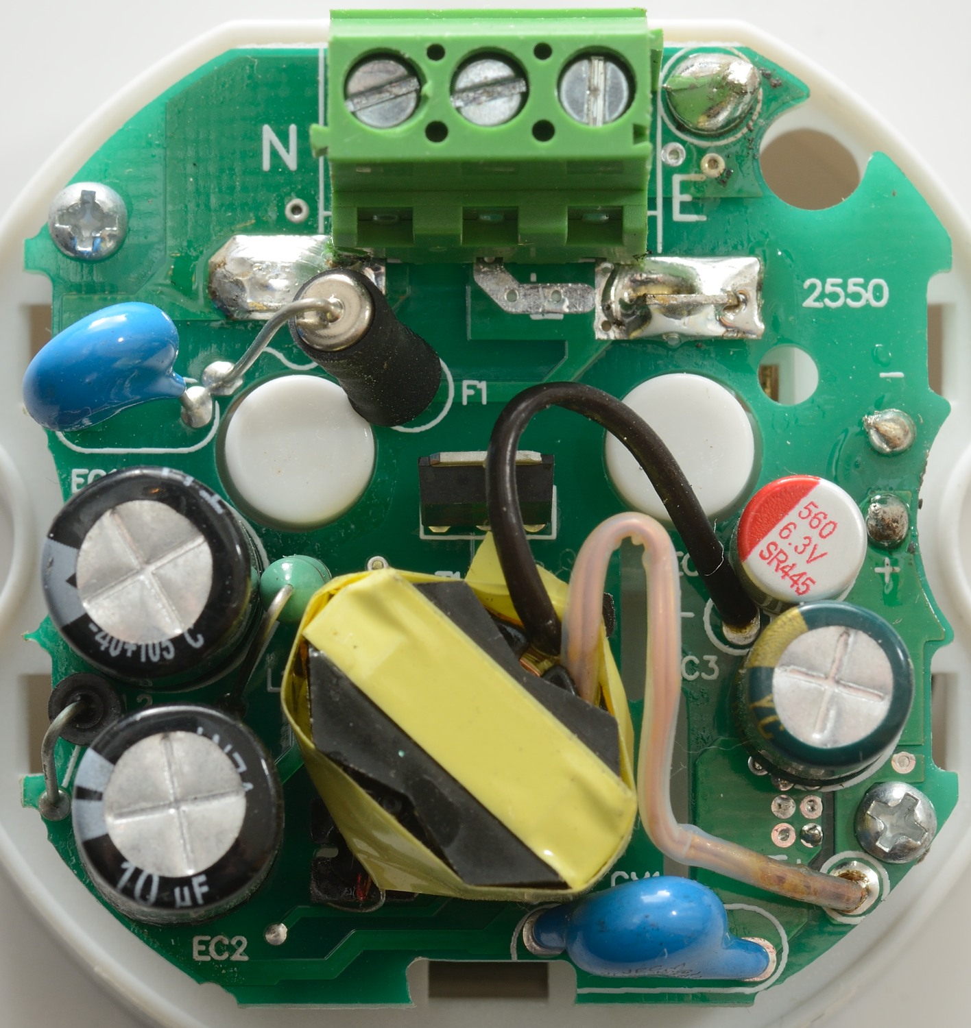
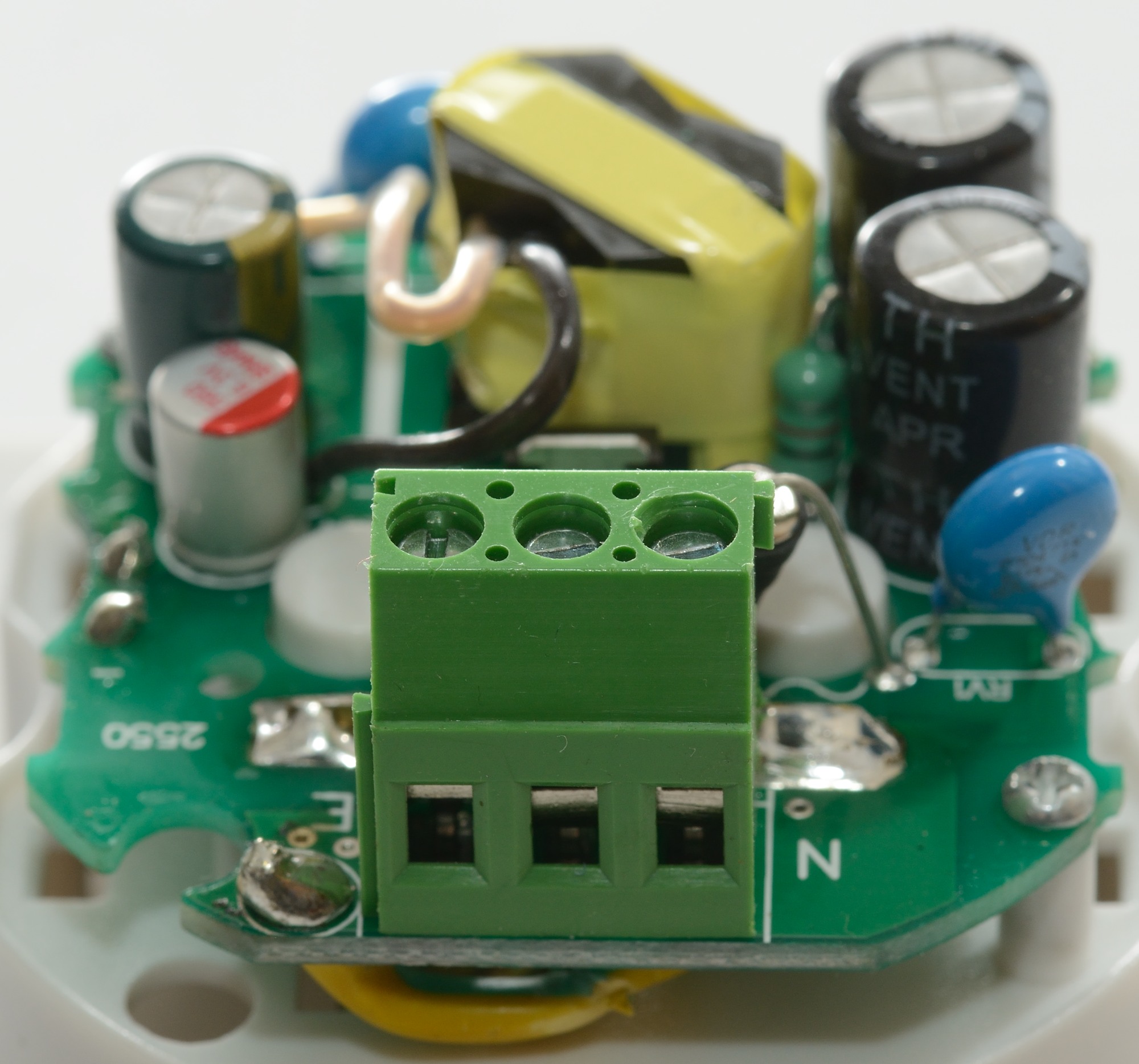
There is both a fuse (F1) and a transient protection (RV1: MOV). Between the two capacitors (EC1 & EC2) is both a inductor (L1) and a ferrite bead (L2). There is also the usual safety capacitor (CY1) and the transformer has flying leads for extra safety distance.
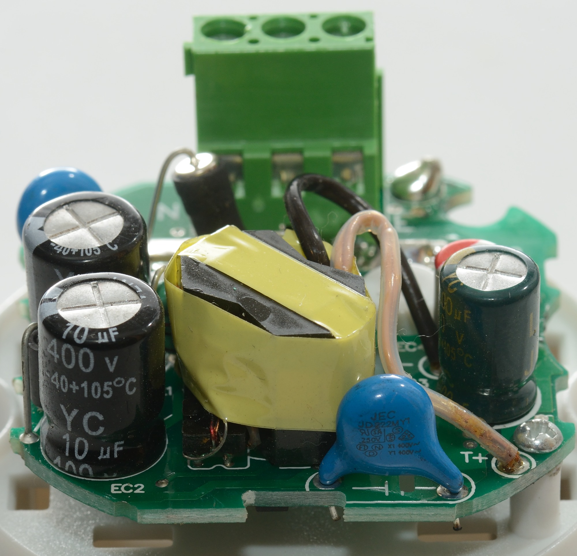

The safety capacitor has, as usual, lots of approval markings.

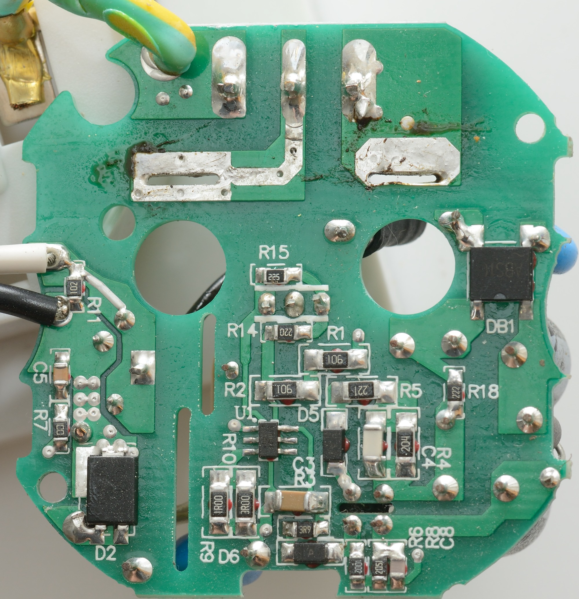
To see this side of the circuit board I had to unsolder the mains socket from the circuit board.
On the other side of the circuit board is the bridge rectifier (DB1), the mains switcher (U1).
There is a single rectifier diode (D2)

The requirement for safety distance is only 4mm when across a slot in the circuit board, this is easily surpassed here.
Testing with 2830 volt and 4242 volt between mains and low volt side, did not show any safety problems.
Conclusion
The usb output can easily deliver the rated current, it has low noise, coding is acceptable and it looks safe.
This is a fairly good mains socket with usb output.
Notes
Index of all tested USB power supplies/chargers
Read more about how I test USB power supplies/charger
How does a usb charger work?