anybody use mosfets instead of schottkys for reverse polarity protection? with almost no voltage drop, more current capacity, and about the same or lower price, it seems they would be a good alternative. i see lots of lights using multiple schottkys due to current i guess. mosfets would definitely be cheaper than multiple diodes. would they be a safe alternative? can they react fast enough?
thanks
I’d like to revive this old unanswered thread because I’m curious about the same.
I see that LD-1 (and I guess its successors as well) use MOSFET for protection…but I fail to find any other driver like that.
What’s the reason MOSFETs are not popular in this application?
I have seen many times in different drivers (incl. trustfire, ferei, some unnamed aliexpress buck driver) , just one N-ch FET (between circuit ground and battery/flashlight ground).
Yes I have same question why always designers choose schottkys. If I design my driver I will choose mosfet. One limitation of that approach is Vgs voltage which is about 15-20V but LED drivers which we use have lower input voltages under 10V in most cases. Also there are dedicated Load switches are cheap these days and they have additional protections like overcurrent overvoltage, overtemperature and etc. But most of them have only working supply of 2.5-5.5V
Did Paul Pickering make an error in this article? Here is his diagram for the P-channel solution, but it appears that the body diode is not correct. Correct is in Red. Hard to believe an error from TI and not caught in ED.
Tip: the body diode direction is the same as that of the Gate-Source junction.

The body diode has to be oriented to block current flow when the polarity is reversed.
Can you find a device or part number with a reversed body diode such as you suggest?

It’s not a special device; the whole device has to be flipped over so the body diode is pointing the opposite way from the way you’d normally use it. Some people label gate, source and drain to match the normal orientation, some label them to match the flipped orientation.
I have used MOSFETs (usually P-channel, but N-channel can be used as well) for reverse polarity protection. Especially where I want to avoid voltage drop (like my battery monitoring tailcaps). From what I’ve seen, they with great. I know loneoceans has used a P-ch as well in his GFS16 tailcaps. The driver in the Convoy H1 uses a N-channel FET for RPP.
There are 2 ways to have reverse polarity protection in a low voltage high current device like a flashlight.
Either use a schotky diode, but that is quite inefficient above 1A, or an MOSFET to have extremely low resistance, in exchange of having to power it. It’s not usually an issue most of the time though.
But in most drivers here reverse protection is only at MCU power supply rail. The consumption is very low current about few miliamps so there is no need to use any high power mosfet device at all. But big advantage is eliminated voltage drop which is also depends of driver temperature.
i believe it can be done, just not with anything as shown in the ED article referenced in post #3 and shown in post #5. My point was that the device is drawn incorrectly; there is no such device with an internal body diode in the direction shown; in electronics and life, the details matter.
And we have yet to see anyone post up a schematic of using a FET for RPP, lots of talk but no action.
Do you know how exactly work the pmosfet reverse protection. I will explain it if you don’t know. In your previous post you show mosfet Which is used as load switch no for reverse protection. So when you connect p mosfet with forward biased body diode it will conduct in first time. After that current will flow across the load and will we have closed loop. When current circulate that will turn on the mosfet and main high current will flow between source drain. In that case voltage drop is determined only from ohmic resistance of mosfet. Also in article there is very good explanation how circuit work. I just explain here the same thing.
@icpart, sorry, I always think of reverse polarity protection in a whole system, like a battery pack.
Wow, someone likes to have everything handed to them on a silver platter!
If you followed the link that I provided to loneoceans’ project, you would have seen lots of details, but maybe not a schematic.
If you would have followed the link I provided to my Convoy H1 teardown, you also would have seen a N-ch in action, though no schematic.
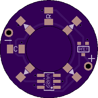
And I apologize for not creating a professional looking schematic for a flashlight part, but here’s a detailed look at a simple board I have at Oshpark where I’m protecting an IC with a P-ch (most should work, but I currently am using NTS2101PT1G)
No action my arse…. some people! :rage:
TL;DR
… loneoceans’ project, you would have seen lots of details, but maybe not a schematic.
…
my Convoy H1 teardown, you also would have seen a N-ch in action, though no schematic.
…
That FET is only rated for 1.4 Amps, easy to get a Schottky diode that can handle more than that.
“I have at Oshpark where I’m protecting an IC with a P-ch (most should work, but I currently am using ”NTS2101PT1G”
No need to get ruffled feathers.
But like i said, nobody has been able to draw up a simple schematic; i don’t need it i already know how to do it, just seeing how serious folks are about understanding what they are talking about.
Serious enough that we make our own stuff to fit our own needs. You act like if we didn’t post a schematic that we don’t know what the heck we’re talking about.
And generally the diode (or FET) is only used to protect sensitive components like an MCU or other IC. Generally there’s no need to have the full load going through the polarity protection.
So FET in this application is actually not unusual, just the drivers that are evolution of nanjg keep using it?…
Good to know. ![]()
So…again, why are diodes used?
In articles I see that price is an argument - but ZLLS410TA that I see recommended, at least in Texas Avenger, isn’t cheaper than a FET.
Size is not very different either, though it may be depending on the components chosen.
I’m interested FET-based drivers and what sparked my question was a thought that gate is typically driven off a MCU pin. And reduction of MCU voltage drops gate voltage, effectively increasing FET resistance.
But I’m not sure if I’m correct about that.
A diode is simple to understand and easy to implement.
If you experiment with FETs on the bench you will find that they can conduct in both directions with nothing attached to the gate. They are charge controlled devices and the capacitance (Miller) of the gate junction allows it to charge up and turn “on”. It will stay on as long as that charge is present. So some form of gate control is needed, either passive resistor network or from some device, depending upon the degree of protection desired.
Also there is another problem with fet. To be turned on it’s need higher input voltages like over 2,5V. Yes there is a mosfets with low Vgs voltage but they are more expensive. Also diode is better solution for low voltage powered devices compared to mosfet. In most drivers here there is direct control of mosfet from MCU and powered from LDO there’s is limitations of voltage and current capability of MCU output. Is better to be used gate driver but this cost additional space on PCB.