 Hello, i made several mods, but this one is far the best:
SAIK SA - 305, 3 Cree XML U2, Driver mod with 3 x 2,8 Amp, 3,7 V 5000 mAh Battery,
Lens is an UV filter, 3 Mode ( low, mid , high ) The typical hole is filled with copper.


Hello, i made several mods, but this one is far the best:
SAIK SA - 305, 3 Cree XML U2, Driver mod with 3 x 2,8 Amp, 3,7 V 5000 mAh Battery,
Lens is an UV filter, 3 Mode ( low, mid , high ) The typical hole is filled with copper.
nice mod, but I have to say... your wiring makes me want to cry. Is it just me or does the bare copper wire in the 6th photo look like it's a hairs width from shorting to the negative ring on the driver board?
looks like it IS shorted to me
why no pictures w/ the light ON?
It is not bare copper wire, it is isolated with lack.
I hope my english is right.
I made i new picture when it is turned on high!
I use this flashlight now for almost 4 months.
Moin daysoft,
your mod looks very McGyver'ish... were is the Swiss army knife? ;-)
Clear "Coating" is the word you are looking for... "lack of" is "Mangel an" in English.
www.dict.cc is a good start to check your English or even Google translate might help in some cases.
It's a mini-DRY !!! Nice job.
Way to go .
Yeah baby !
Love it , its a monster !
Wiring diagram please , Modes ?
Very nice indeed. Good job!
Brilliant!
Beamshots?
Very nice work
Very, very nice! Nice "outside the box" thinking with the driver mounting. 8)
I believe the reference to "lack" was meant to be 'lacquer'.
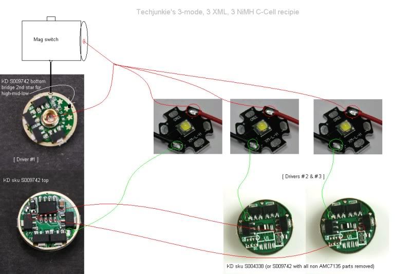
The drivers are all from Kaidomain: The master is an http://www.kaidomain.com/product/details.S009742,
the slaves are http://www.kaidomain.com/product/details.S006717 ( with piggypack 4 x 7135 )
The master driver is a Njang 105A, https://budgetlightforum.com/t/-/1022 with stars to change
the modes, i normally take 3 mode ( low/mid/high - second star )
We have the last days much fog, so beamshots are not possible!
Hat meine Frau auch schon zu mir gesagt, weil ich schon vieles
unkonventionell repariert habe!
Thats said my wife also to me, while i repaired something!
Daysoft, can you post a wiring schematic for your setup? Also, you said your slaves were the 47135 drivers with 47135 piggy backed. Why not just use the 8*7135 like you used for the master but with the controller chip removed?
This solution was cheaper and i had the parts at home!
I am not good in drawing schematics, but it is really easy to connect, All drivers has normal + and - and each driver output go to 1 led. The master circuit must connect with the
pwm output from one 7135 IC to one of the 7135 IC´s from
each slave circuit! So the slave units become there pwm signal and all circuits have the same modes!
Hope that will help you!
Hello here you can get the driver schematic from the 7135 IC: http://html.alldatasheet.com/html-pdf/202789/ADDTEK/AMC7135PKF/219/1/AMC7135PKF.html
The pwm input ( not output like i say in the previous thread ) is the VDD Pin, it is the pin that is connect to the atmel chip!
For the slave units it is of course much easier to take this circuit: http://www.kaidomain.com/product/details.S004338
More info please! What reflectors did you use? What did you use for the heatsink? What size emitter stars?
I imagine it's wired like this:
Now I wanna do one of these! Oh, yeah: Which battery?
Rich