
This an output and voltage test of the new ultra-high CRI Nichia Optisolis leds. Thanks to Clemence who was able to sell some very early samples of these leds for very little money. A discussion thread on these leds was here. This post is strange enough not about the most important aspects of the Optosolis leds: the tint, CRI and colour reproduction, simply because I do not have the equipment for measuring that. I hope that maukka at some point can do tests on tint and spectrum, especially on spectrum changes at increasing (out of specs ) current. All I can say is that the tint looks great and that I do not see obvious tint changes when current is varied from 20 to 1000mA.
These are midpower leds that come in currently 2 colour temperatures: 5000K and 3000K. They are completely new developed types of leds, the 5000K Optsolis is based on a new 420nm blue led, the 3000K Optisolis on a (new?) 445nm blue led. They both do not suffer from the cyan dip and the visible part of their spectra come very close to the standard illuminants for their colour temperature.
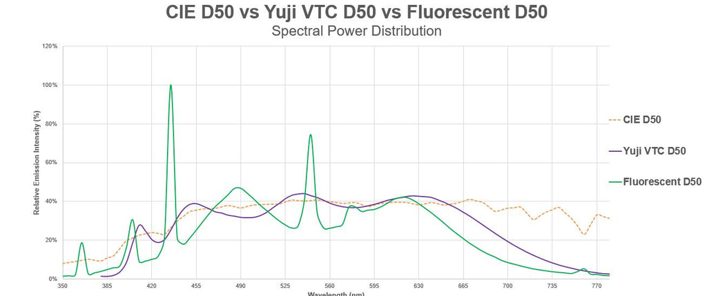
The only existing leds (AFAIK) that can match the colour reproduction performance of the Optisolis are the Yuji VTC-series leds, of which I tested the 'D50' version of the 5730 variant a while ago here: https://budgetlightforum.com/t/-/45612. Here are the spectra of this Yuji led and the 5000K Optisolis led next to each other, as you can see they are very similar apart from their primary led peak:

My questions are:
-can the Optisolis leds beat the meagre performance of the Yuji 5730 D50 led?
-Do they have at least a more uniform illuminated die?
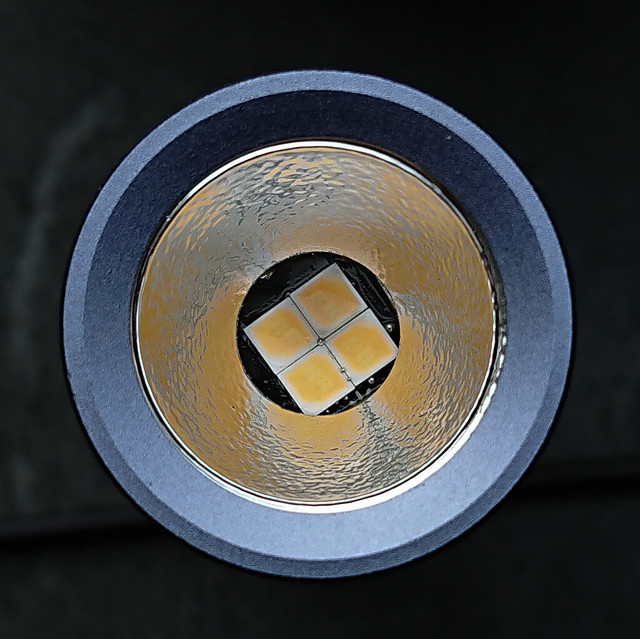
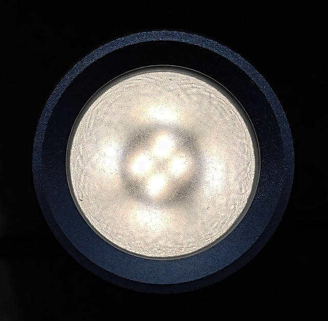
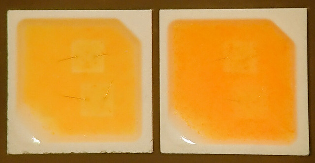
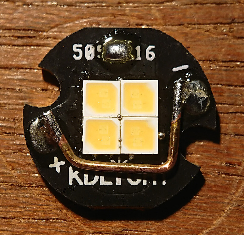
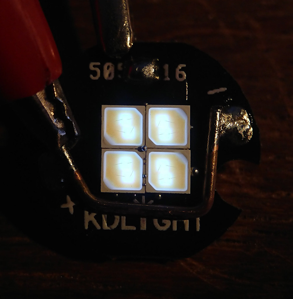
To start with the last question: no, their die uniformity is even worse because embedded in the led are two separate dies that are very a-centric. If only Nichia had chosen for 4 dies evenly distributed over the led...  . Here's the two leds at very low 0.5 mA current:
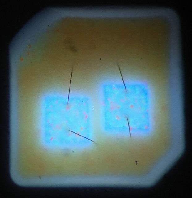
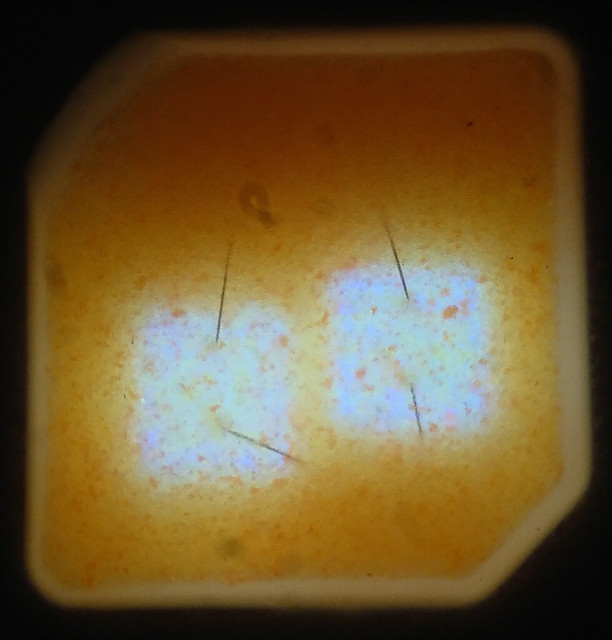
The light green specs in the 5000K die I have never seen before 
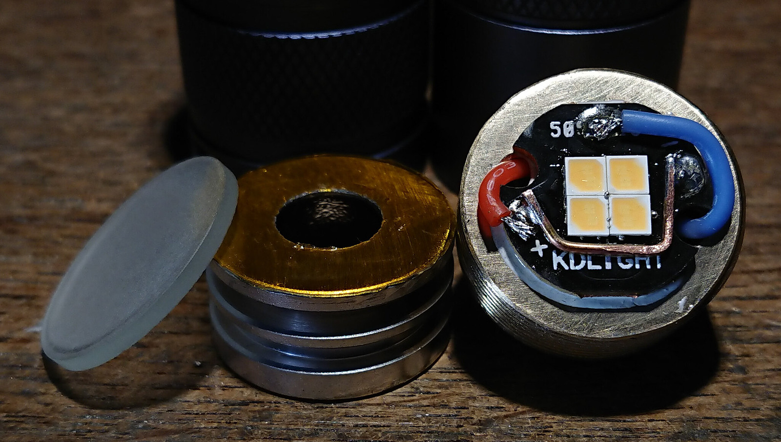
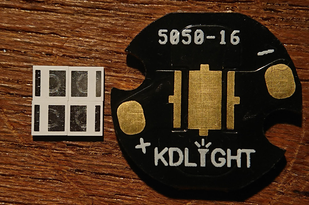
For the output tests I reflowed the leds onto my copper core non-DTP two-pad 'Nichia 119' boards.
The output test was done like all my more recent emitter tests. I described it in detail in my XP-L test. , with two minor differences that should not matter significantly for the results: I used my Integrating sphere no. II instead of no. I, and for the current I used a clamp meter, which appears to measure 0.1A lower than the power supply current-reading that I used before.
In summary: 1) just one led was tested, reflowed on a non-DTP copper board, 2) I used my large version II integrating sphere with high quality luxmeter, 3) the output numbers and voltages were measured with the led close to 'steady state' for each current, so warmed up and settled, you should be able to get these numbers in a well heatsinked flashlight. Mind that these are output numbers of the bare led, in a flashlight there will be losses from light obstructions, lens and optic, 4) output is in 'djozz-lumen' defined as 1/550 of the output of my Sunwayman D40A on high setting, which I hope is close to the real lumen, but at least is consistent over all my emitter tests done in integrating spheres. 5) my output tests usually show great performance at currents outside the maxium current of the datasheet, but I have no data on the longterm survival of the leds at these currents, the lifetime may well be significantly reduced.
Here's the results:
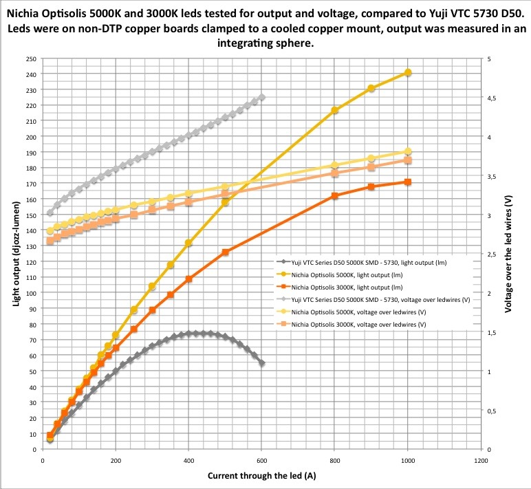
(error correction, under the graph: (A) should be (mA) )
What can be seen?:
*the Yuji led is beaten by a great margin, both in output and voltage. In fact up to 400mA the Optisolis leds are surprisingly efficient, for the 5000K Optisolis at 60mA I calculate 126 lm/W (I compensated for that my djozz-lumen is most likely 9% high compared to the real lumen)
*the output of both Optisolis leds are very stable, during the test I saw no output dropping at any current, even not at 1A. This implies that the temperature sag at least at these for BLF-standards low currents, is low.
*the Optisolis leds are rated for max 65mA 'pulse current', (edit: newer specs just posted by Clemence show max 100mA for the 5000K and 150mA for the 3000K Optisolis) but when mounted well like in my test they easily survive 1A. During the 5000K Optisolis test I kept the led at 500mA for 40 minutes to see any damage, it stayed within 0.5% of the initial output !
*the voltage stays low at all currents, in case you want to use these leds in a single li-ion flashlight, make your current regulated!
Conclusion:
As mentioned at the start of this post, this post is not about the tint, but at least the performance is way better than the datasheet promises.So much in fact that these leds unexpectedly are actually usable in a flashlight 

 .
.