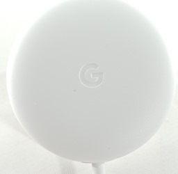
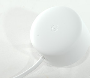
Google Home Mini Charger
Official specifications:
-
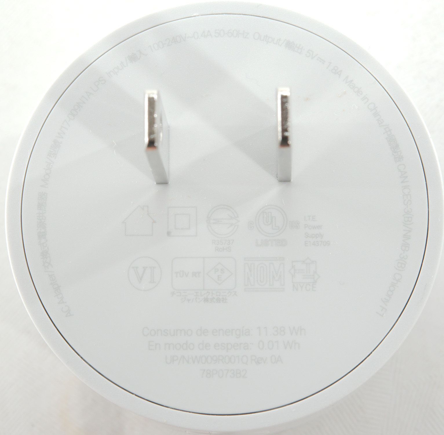
Mains voltage: 100-240VAC 50-60Hz
-
Output: DC 5.0V 1.8A
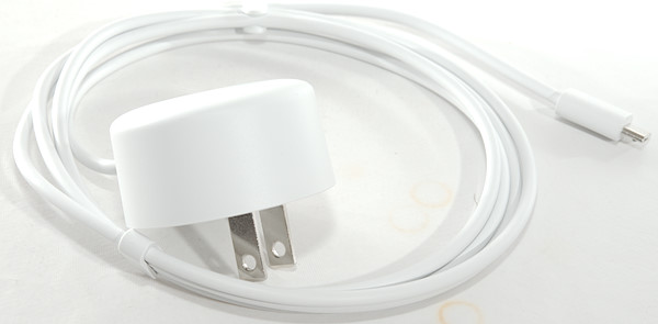
I got it from a reader
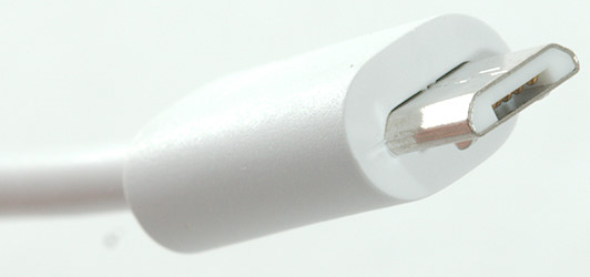
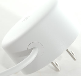
This charger has a build in usb mini cable and connector.
Measurements
-
Power consumption when unloaded is 0.005 watt
-
USb output is coded as usb charger (DCP)
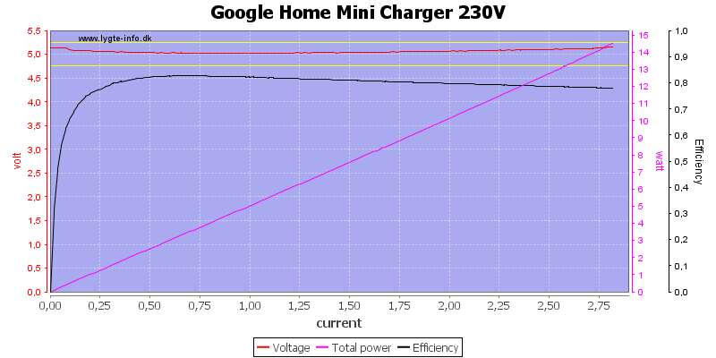
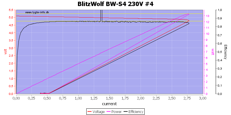
Output voltage looks fairly stable, this means the charger has a cable compensation build in. The output current is way above the rated 1.8A, but below 3A.
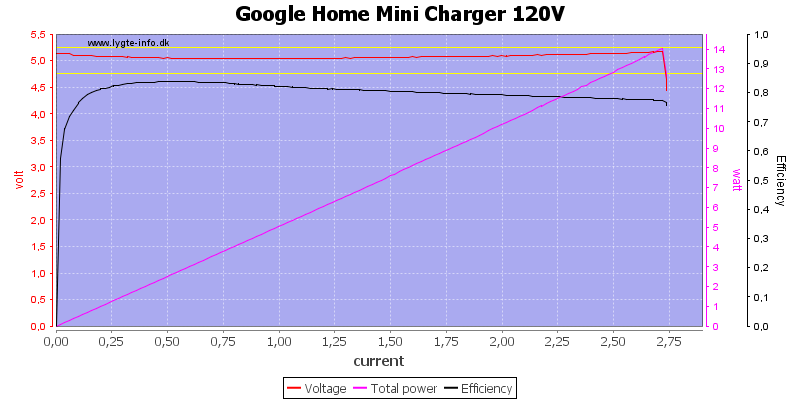
There is not much difference between 230VAC and 120VAC
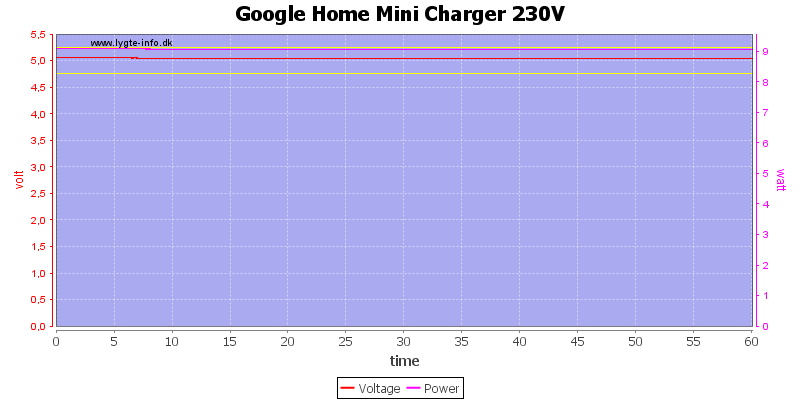
Running with 1.8A for one hour did not show any problems.
The temperature photos below are taken between 30 minutes and 60 minutes into the one hour test.
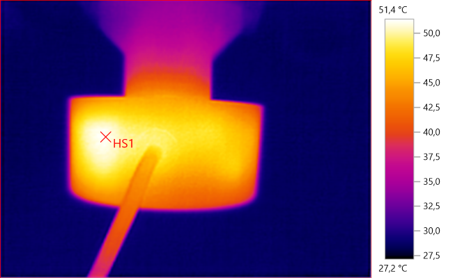
HS1: 51.4°C
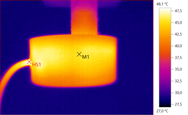
M1: 45.2°C, HS1: 48.1°C
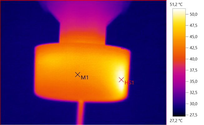
M1: 44.0°C, HS1: 51.2°C
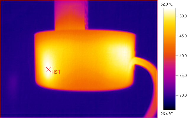
HS1: 52.0°C
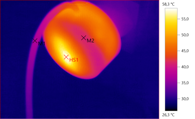
M1: 37.1°C, M2: 41.3°C, HS1: 58.3°C
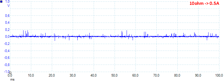
Noise at 0.5A load is: 12mV rms and 370mVpp.
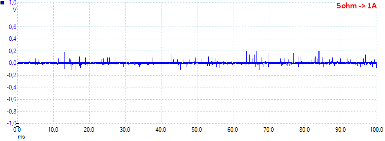
Noise at 1A load is: 15mV rms and 419mVpp.
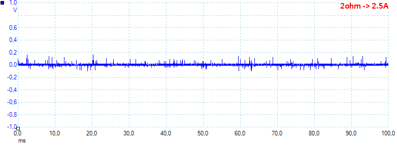
Noise at 2.5A load is: 18mV rms and 393mVpp.
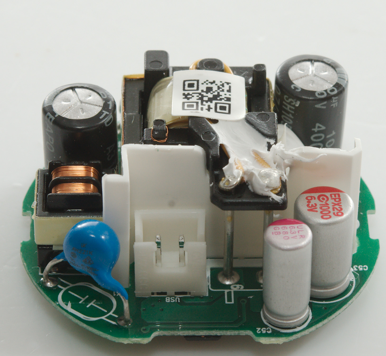
Tear down

It would not pop open in my vice and I had to cut.

The cable is mounted from the outside with a clip on the inside to hold it.
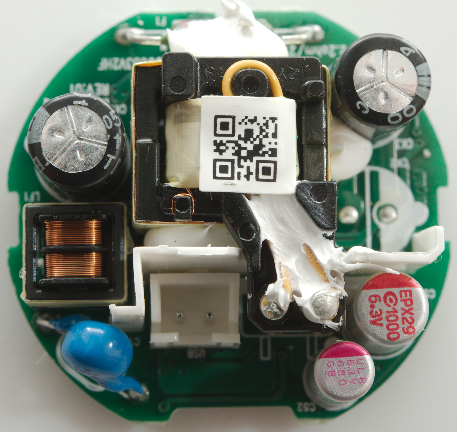

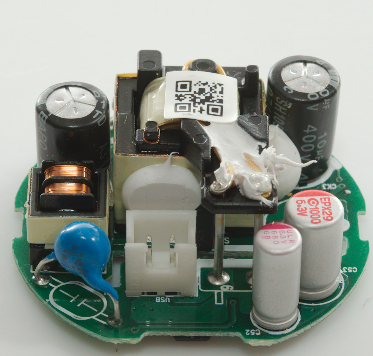
The charger has a fusible resistor (F1) at the mains input, there is also a common mode coil (LF1) and a safety blue capacitor (CY1). Between the transformer and the shield is a switcher transistor.
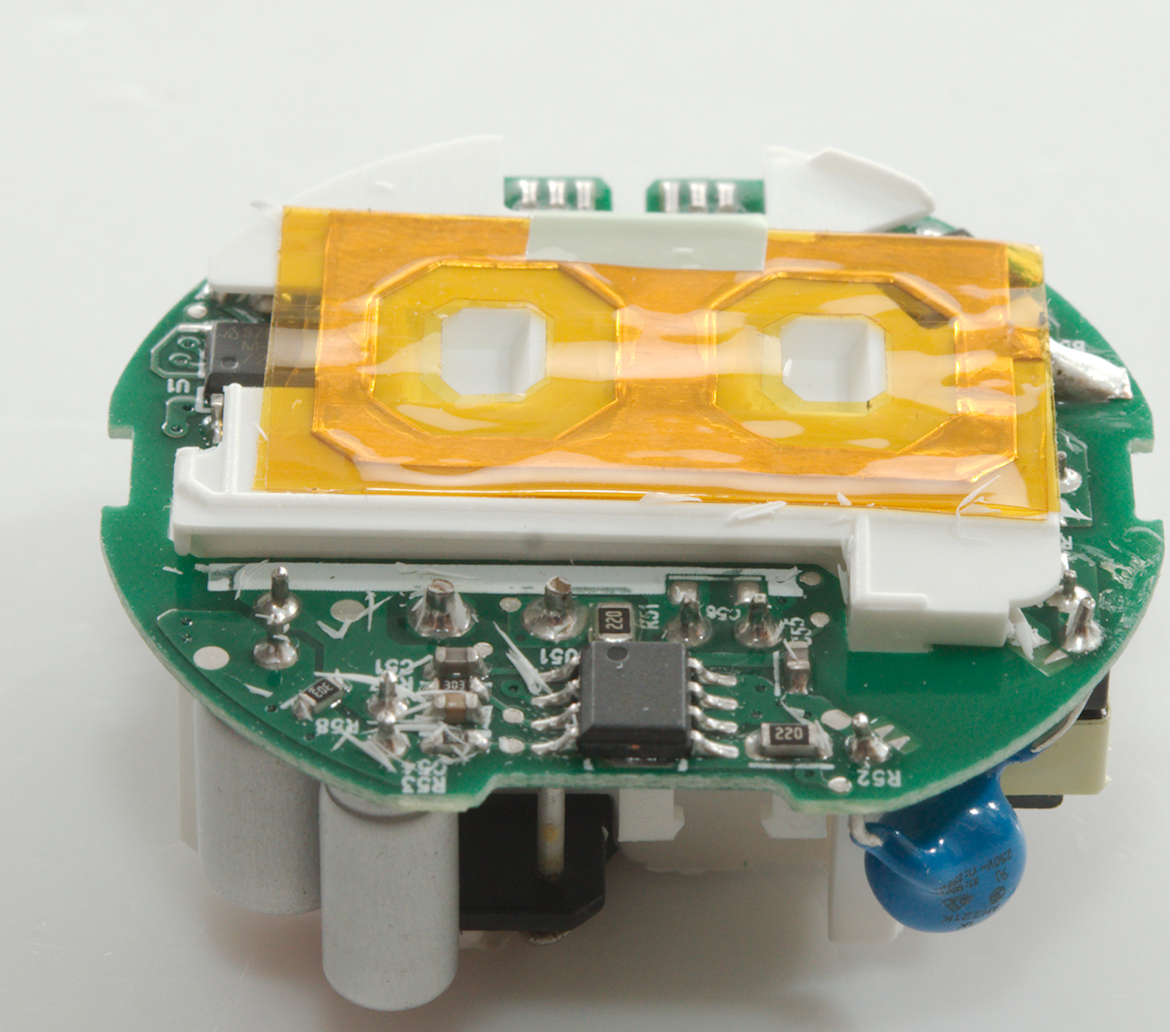
There is a white plastic shield between the mains section and the low volt section and the transformer has the low volt wires coming out at the top.
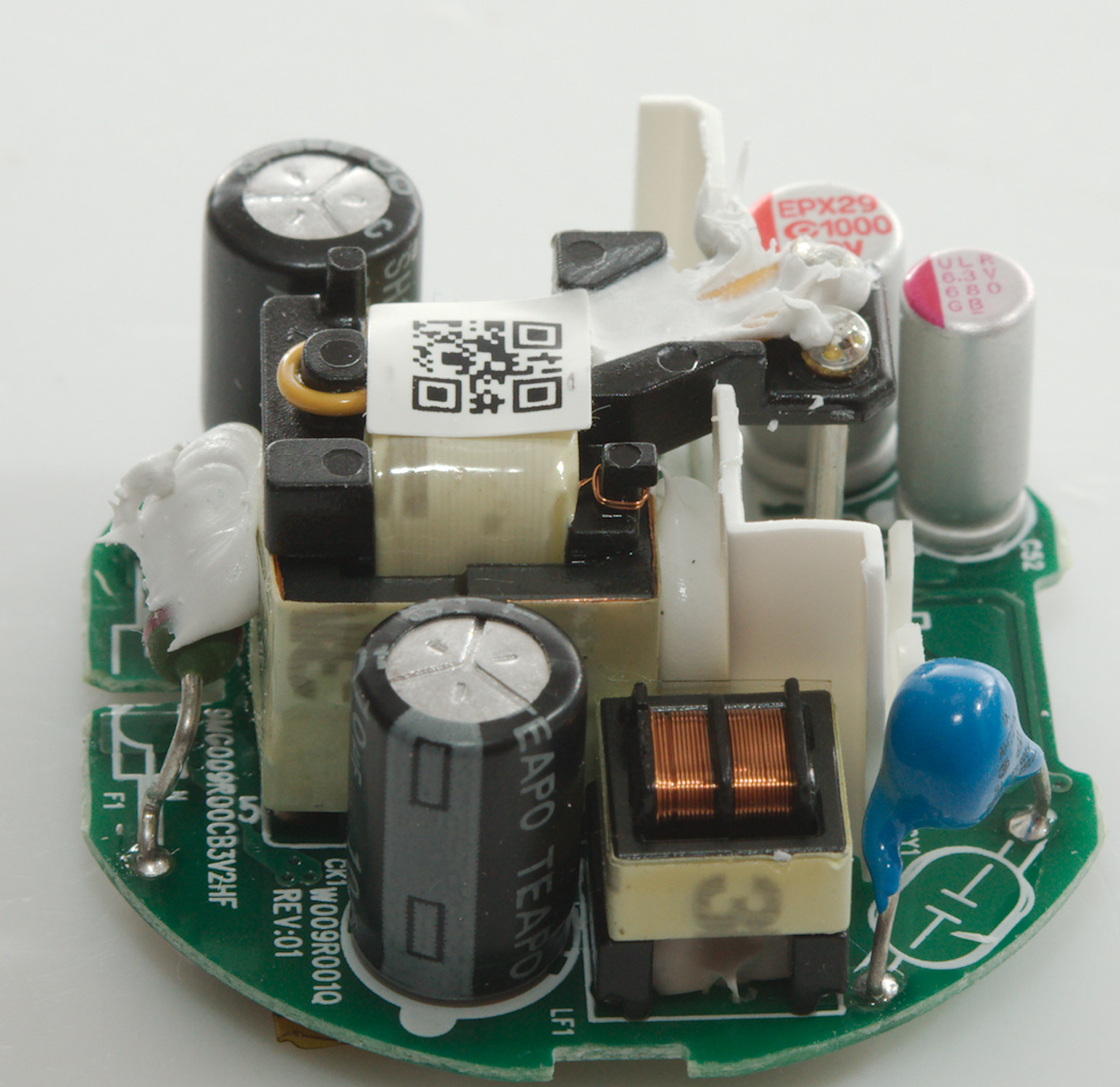
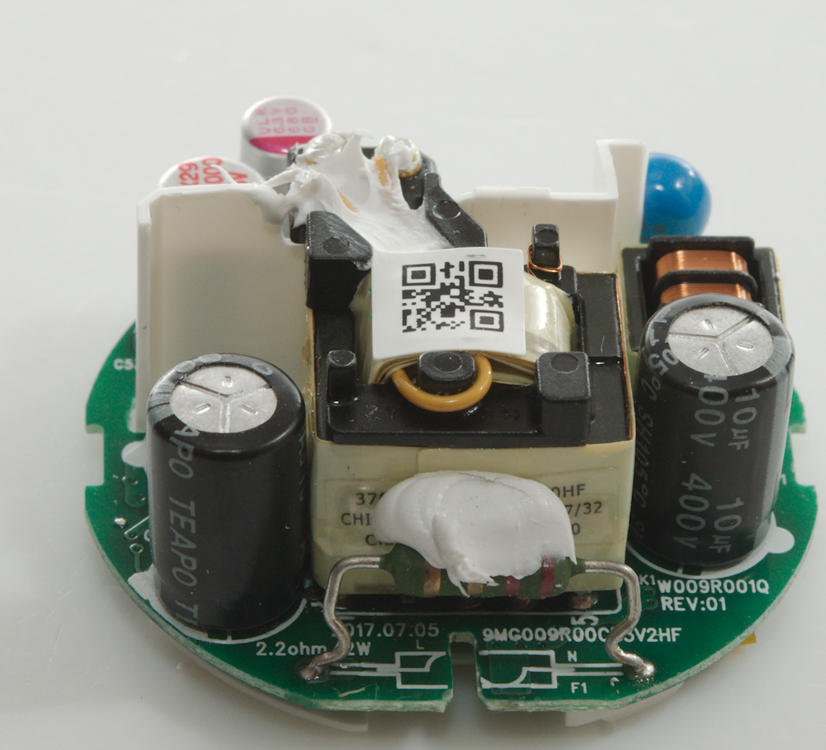
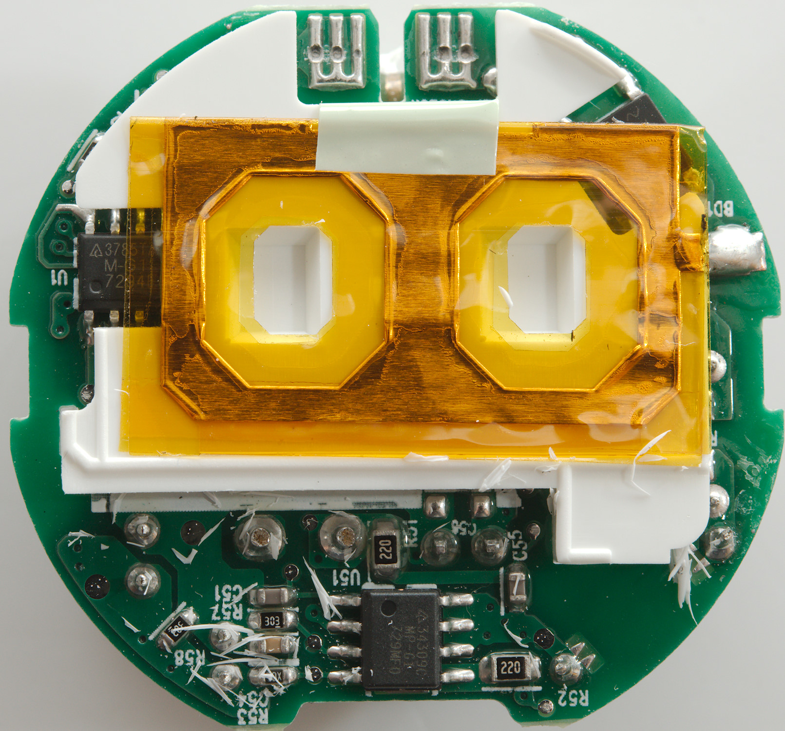
The plastic shield is also present on this side of the circuit board and there is some shielding on it.

After disconnection the shielding the plastic shield could be removed.
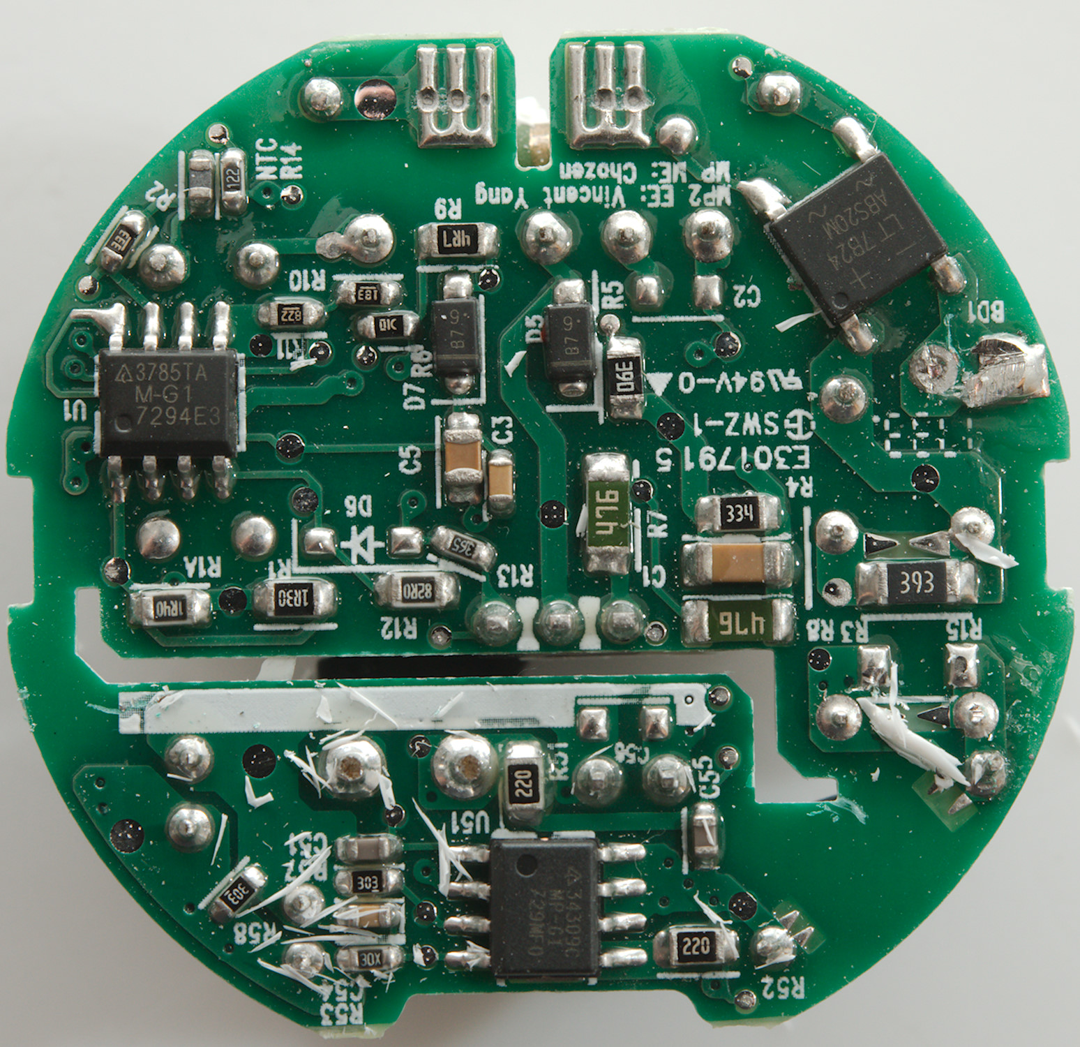
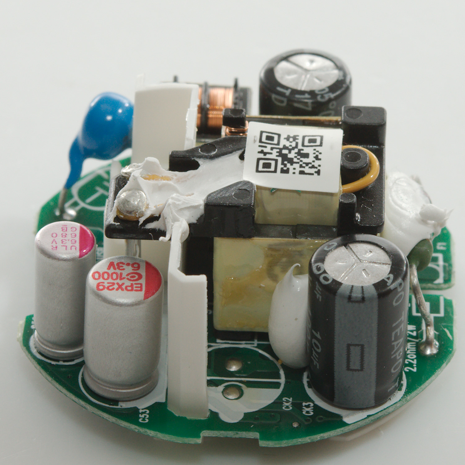
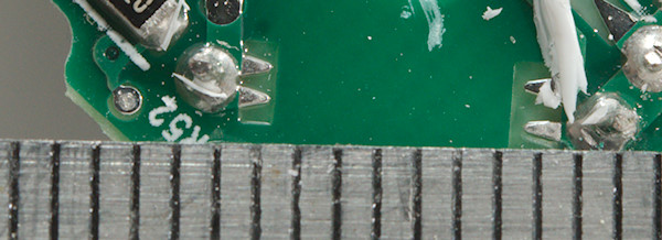
At the mains input is a bridge rectifier (BD1) and a switcher (U1: AP3785T) and on the low volt side a synchronous rectifier (U51: APR34309C).

Without the plastic shield is is possible to see a corver of the switcher transistor.
No problem with isolation distance.
The charger failed both the 2830 volt and 4242 volt test, i.e. it is not safe to use anywhere. This must be a fault in the transformer, there is not any other place where the isolation can fail.
Conclusion
The construction of this charger looks nice and safe, but for some reason it failed the high voltage check. I tried testing it again after the tear-down, but I cannot locate the problem.
The performance of the charger is fine and it has a good coding.
Due to the fail I will not recommend this charger, but I doubt it is a general problem.
Notes
Index of all tested USB power supplies/chargers
Read more about how I test USB power supplies/charger