KD 7135 V2 drivers 3040/2280/1520 mA 8 modes
Reviewer's Overall Rating: ★★★☆☆
Summary:
| Size: | 17mm |
| Voltage: | 2.5-4.5V |
| Regulation |
Linear Regulator |
| Current: | 3040mA |
| Modes: | 8 groups selectable |
| Price Paid: | $4.79 |
| From: |
Pros:
- Well regulated and efficient driver
- Has memory (enabled by soldering)
- Has 3-level groups low-med-high and high-med-low
- Has a very high PWM frequency giving a steady light
- Has a sort of low voltage protection
Cons:
- Low mode is far too low, only glowing
- Memory kicks in 0.5-1 sec after switching on (would prefer after switch off)
- Selection of groups and memory involves soldering
- Can only be used with 1 Li-Ion cell due to power dissipation
2280mA version here
1520 mA version here
Features / Value: ★★★★☆
Mode Groups
The 8 groups are as follows:
1. default (no solder blobs): Low(glowing) - Medium(35%) - High(100%) - Low(glowing) - Medium(35%) - High(100%) -Strobe(10Hz) - Blink(2Hz) - SOS(slooow) - Beacon
2. High(100%) - Medium(35%) - Low(glowing) - High(100%) - Medium(35%) - Low(glowing) - Strobe(10Hz) - Blink(2Hz) - SOS(slooow) - Beacon
3. High(100%) - Medium(35%)
4. High(100%) - Strobe(10Hz)
5. Medium(35%) - High(100%) - Blink(2Hz)
6. High(100%) - Medium(35%) - Blink(2Hz)
7. Low(glowing) - Medium(35%) - High(100%)
8. High(100%) - Medium(35%) - Low(glowing)
The Beacon mode is 2 sec on - 10 sec off.
The SOS mode is super slow (12 sec signal, 8 sec pause).
The PWM frequency (for low and medium) is very high at 15000 Hz.
Mode switching
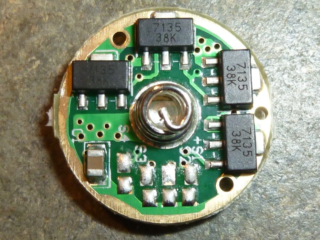
The KD 7135 V2 has four soldering pads (numbered S4,S3,S2,S1 from left to right) on the bottom side to select mode groups by applying a solder blob connecting one or more of the pads to the corresponding ground pad.
[EDIT]: Beware of the schematics on KD's site. It is faulty for the last 4 modes. KD's site seems to be corrected now.
the mode selection should be:
1: no solder blobs
2: connect S2 to ground with a solder blob.
3: connect S2 and S3 to ground with solder blobs.
4: solder blobs on S2, S3 and S4
5: solder blobs on S3 and S4
6: solder blob on S4
7: solder blobs on S2 and S4
8: solder blob on S3
Mode Memory
This can be selected by applying a solder blob at S1. The mode memory snaps in about 0.5-1 second after a mode switch. I normally prefers memory after switch-off so I do'nt have to tap twice to shift level.
Build Quality: ★★★★★
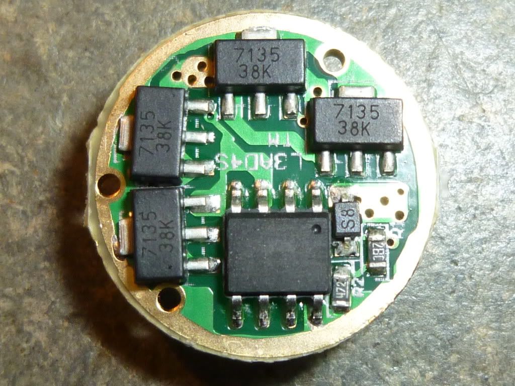
Seems to be fine (like NANJG drivers). In fact I don't know which brand this is. The circuit board is marked: L3AD4S TM. But it should withstand normal soldering with a fine tipped soldering iron.
The MCU is without marking but is connected like a PIC12F629. So home programming is not as easy as for the ATtiny13 (BLF project by Tido).
Battery Life: ★★★☆☆
Linear regulators with 7135 devices normally are well regulated and efficient. At lower battery voltages the drive becomes direct with a very little loss. The high current is hard to the battery and demands a quality type battery (low internal resistance). The driver is not suited to use two LiIon cells as it will become too hot (4 additional Watts has to be dispersed for each ampere drawn). The low voltage protection is activated at 2.9 V where the current draw jumped from 0.69 A to 0.13 A. This is still a much too high current draw from an un-attended battery at 2.9 V. At 2.65 V the current draw was down to 10 mA. The MCU itself draws about 2 mA.
Current Output: ★★★★★
The output current of 3.04 A is fine to drive the XM-L fully but I would prefere to remove a few of the 7135 with a heat gun and use them as cheap spare parts.
The driver has no boost capability so it must be expected that the output falls at lower battery voltages where the drive becomes direct with no regulation.
The driver comes complete with a (rather thin) red and a black lead to connect to the LED.
Summary: ★★★☆☆
This driver could have been the answer to many peoples prayers regarding drivers with its low-med-high and high-med-low modes without blinking modes, but the glowing Low is a deal breaker. There is the possibility to make a two level (100% - 35%) light though and the choice of memory or no memory is very fine. But compared to the late NANJG 105C I have to withdraw a star for the unusable low and the hard-to-reprogram MCU.