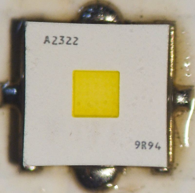
OSRAM KW CSLNM1.TG (1mm2), KW CSLPM1.TG (2mm2) & CULNM1.TG 1mm2 version of Oslon boost HX
Some of us prefer to call them White Flat 1mm or White Flat 2mm.
This is edited thread so first available version that we managed to test is White flat 1mm (CSLNM1.TG) so first part of edited post starts with it:
Led4Power brought us this interesting emitters and I had opportunity to test this led in direct comparison with good old XP-G2 S4 2B dedomed.
Used same host(uniquefire 1503, 50mm aspherics with selected lenses), same driver(Djozz FET driver), same 18650 cell. Testing equipment uni-t clamp meter and uni-t lux meter.
Test subject Uniquefire 1503 fitted with XP G2 S4 2B has 255kcd performance. 950FC or 10225Lux at 5 meters.
Mine test started with low current 4.35V cell LG18650BD1 and I roughly got this results:
4.2V 5.35 A 1180FC, 4.1V 5 A 1150FC, 4.0V 4.8A 1150 FC, 3.9V 4.6A 1150 FC, 3.8V 4.5A 1150FC, 3.7V 4.1A 1100FC, 3.6V 3.8A 1050FC, 3.5V 3.3A 950 FC with new OSRAM KW CSLNM1.TG. It equals performance of the best G2 at very low current draw which means it will kill in lux performance any XP (E2 or G2) based emitter!
Now torture test. Torture for this emitter will be any cell in Samsung 30Q rang or better if used in FET DD setup which of course will pull a lot of current. So in mine test emitter survived over 7A of current draw for more than 3 minutes(for couple of times). After cool-down it did not loose initial properties(performance remained the same) which implies that emitter is very robust. This were mine results. I also found that mine test subject had best performance at around 5.8-6A (1200FC)
So in mine test OSRAM KW CSLNM1.TG over-performs old G2 significantly in everything except die sizeThis small emitter is like Viagra. It does not falls in performance that easy :smiling_imp:
My advice for such single cell FET DD setup is that you use low current cell. Sanyo GA and mentioned LGBD1 will work OK but there are plenty of others that could work without harming emitter.
Crucial things could be reflowing: Use as thinner layer of solder paste as possible (needle syringe application) since on this emitter it is very hard to push excess solder off.
Or you could just buy plug and play version on L4P DTP boards. So you can pick 20mm or 16mm
Led4Power uses lead free solder in re-flow process which according to him should have better properties than solder paste.
Led4Power tested it:
Djozz tested it:
Led4Power told that this variations can happen because of excess solder during reflow process:
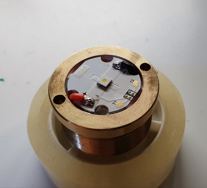
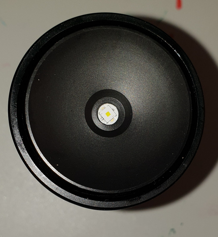
We already have builds with that emitter:
Now we will talk about White Flat 2mm(CSLPM1.TG)
I also had opportunity to play with this larger 2mm white flat maybe even sooner than Led4Power. So this is mine pre- test with classic light meter and clamp meter (so test is just for reference before someone with better equipment test it). Full Samsung INR 30 Q. Single cell 18650 light with FET Djozz driver.
4.2V, 13.4A, 930 FC
4.0V, 12.5A, 950 FC
3.9V, 11.4A,1050 FC
3.8V, 10A, 1250 FC
3.7V, 9.20A, 1200 FC
3.6V, 8.20A, 1150 FC
3.4V, 7A , 1100 FC
Somewhere at 8-9A will be just enough…
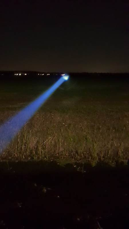
The most beautiful emitter I ever had in my aspheric light. When searching at night in zoom in mode with aspheric light it looks like wide screen TV 16:9 format
But my conclusion this ain’t emitter for single cell fet drivers but you can put it in if you insist and wanna play. Regulation is must if you don’t wanna live on the edge
Also very robust emitter. It can withstand some serious current draw. Add as thinner layer of solder paste as possible.
DJOZZ TESTED IT:
Some of us got larger numbers than Djozz but there is so much variables that could influence on max performance of mentioned emitter but one is sure:
You can’t go wrong if you follow Djozz tests and make everything according to that test.
Because emitters will be driven just fine and they will give better lumen and lux performance than the best dedomed XP- G2 S4 2B or any XP-E2 emitter.
Other additional important stuff and test will be added here. So lets start with this:
ENDERMAN teseted it:
*Newest CULNM+1.TG 1mm2 version of Oslon boost HX L4P review below:
I bought 3 pieces, I plan to put one in my Olight R20 to make a pocket thrower.
Another one will go in my Amutorch JM70 (TA FET driver) which has a sliced SST20 ATM.
The last one ? Don’t know yet… aspheric maybe ? My B158B ? I’ll see…
Looks like a good LED, but it seems like it doesn’t beat the dedomed XPG2 by much in terms of throw in the examples above. E.g. the D80 and S8. I recently measured a dedomed XPG2 (new style) in an S2+ smooth reflector at 29kcd.
Is this an issue of improper focus or reflector imperfections or over/under driving? What are people’s understanding of this?
Ok so it’s a more efficient LED butt its reflowing fickleness and subsequent performance variation makes me a bit hesitant that ultimately it’s worth the bother to take out all my XPG2 S4 2B’s. I just don’t run my flashes for long periods of time enough to really gain from the runtime gains plus what appears to be not that much of a lumen/lux boost.
I mean for the hassles involved I might as well wait for LEP’s to go modder mainstream - as in cheap and prevalent.
As for new hosts sure why not give it a go butt I’m not expecting my socks to get blown off here either. I’ll prolly wait till a GB comes along with one in it too.
Ok. I went into my cold shed for you guys and have some measurements.
I think I usually measure a bit lower than others around here and I measured some lights again to have a good(ish) reference.
I have a almost clear image of the die, but I feel it can be a tiny bit better focused.
I did not measure ampdraw, but I got best results using an old protected keeppower 18650. With better cells I got worse results. So it is indeed better to keep the amps down a bit.
D1s stock (5d) 115kcd
Souponfire thrower, fet dedomed xm-l2 205kcd
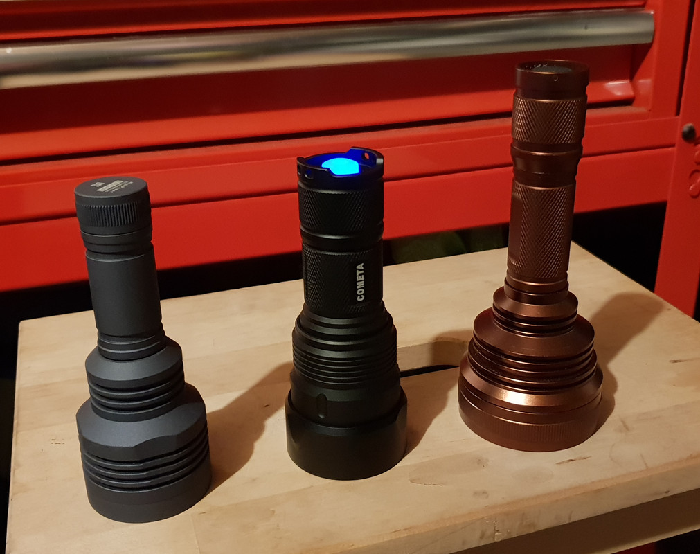
Cometa osram throw king 315kcd