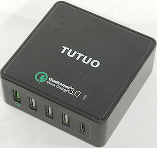
Tutuo USB Smart Charger QC-025PT
Official specifications:
-
Brand: TUTUO
-
Type: Base Dock Charger
-
Features: ALL-in-1
-
Material (Cable & Adapter): ABS
-
Color: Black,White
-
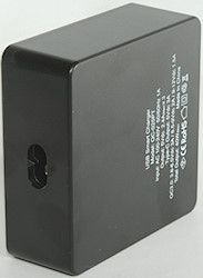
Input: 100 - 240V, 50 / 60Hz, 1A
-
Output: 3.6 - 6.5V 3A, 6.5 - 9V 2A, 9 - 12V 1.5A, 5V 2.4A ( smart output ), 5V 3A ( Type-C )
I got it from gearbest
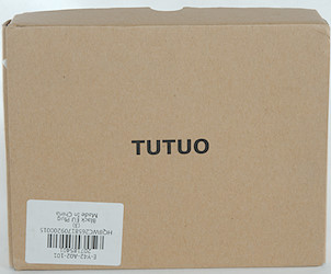
I got it in a brown cardboard box, with only the brand name and a barcode on it.
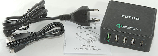
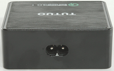
The box contained the charger, mains cable, a usb cable and instruction sheet.

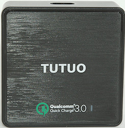
Beside the “3.0” label on top is a blue and red led, The blue part is connected to 5V and the red part is connected to QC and will show some red at 9V and more at 12V.
Measurements
-
Power consumption when idle is 0.11 watt
-
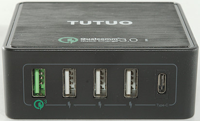
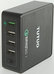
USB output is auto coded with up to Apple 2.4A, Samsung, DCP
-
The 3 USB outputs are in parallel
-
QC output is auto coding with Apple 2.4A, Samsung, DCP and QC3
-
USB C output is fixed at 5V using resistor coding.
-
USB-C output is always on.
-
Weight: 183g
-
Size: 83 x 83 x 32mm
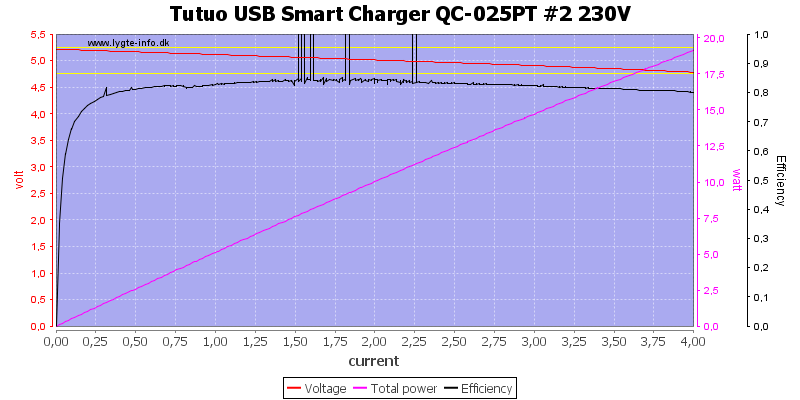
No obvious current limit on this port.
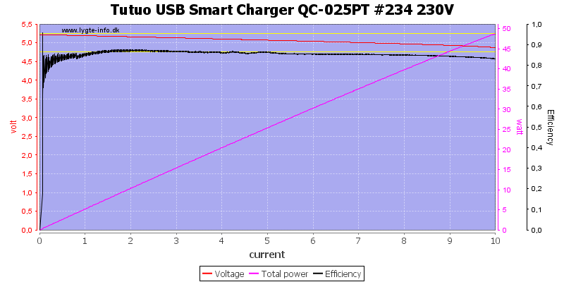
Using all ports in parallel I can draw 10A and without individual port protection this is also what can be drawn from a single port.
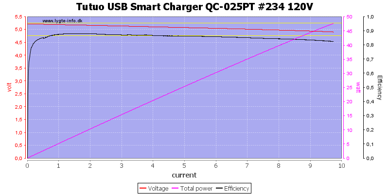
And about the same at 120VAC
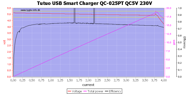
The QC output has a current limit at 3.7A at 5V
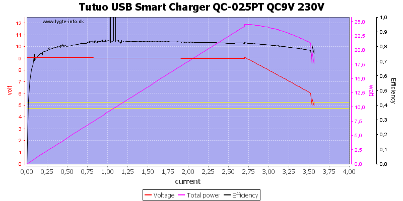
At 9V it drops at 2.7A
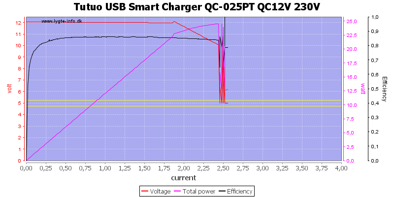
At 12V it is down to 1.8A, this is well above the rated 1.5A
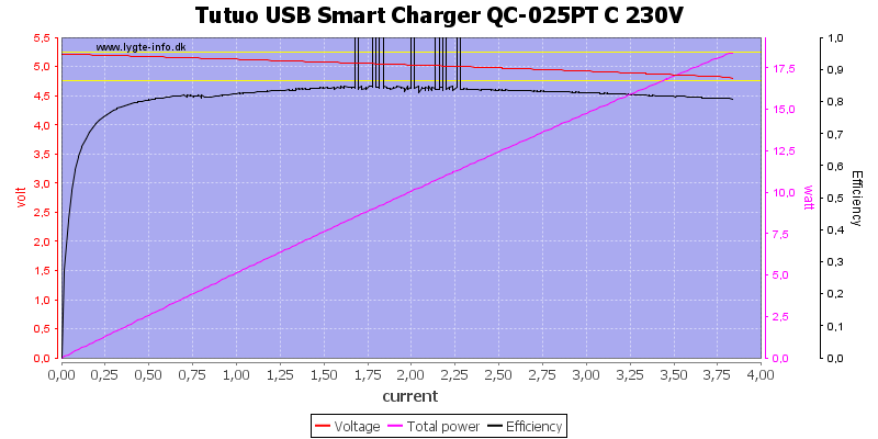
The usb-c output can deliver 3.8A
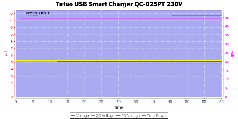
Running the charger with 2.4A on usb, 3A on usb-c and 1.5A on QC 12V worked fine.
The temperature photos below are taken between 30 minutes and 60 minutes into the one hour test.
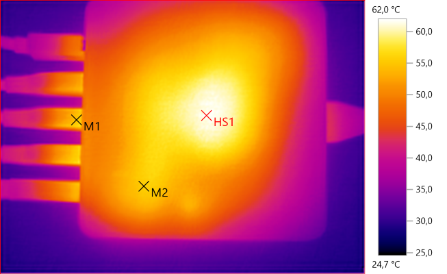
M1: 54.7°C, M2: 55.7°C, HS1: 62.0°C
HS1 is the transformer and M2 is part of the rectifier heatsink.

M1: 51.4°C, HS1: 54.3°C
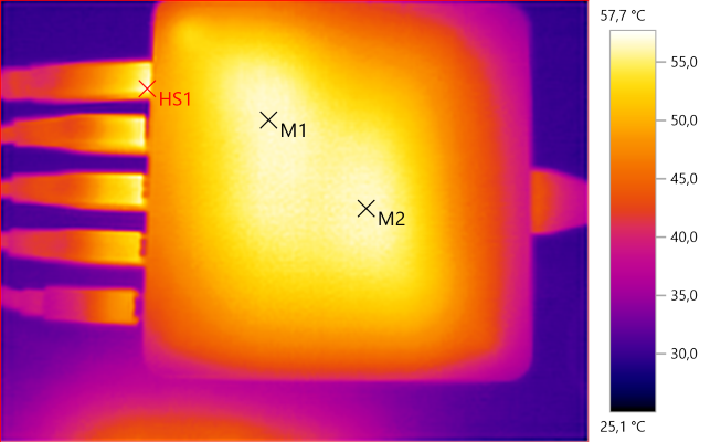
M1: 56.7°C, M2: 56.5°C, HS1: 57.7°C
M2 is the transformer and M1 is the rectifier heatsink.
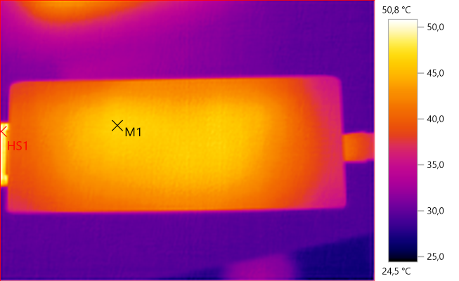
M1: 46.5°C, HS1: 50.8°C
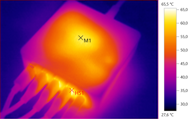
M1: 61.7°C, HS1: 65.5°C
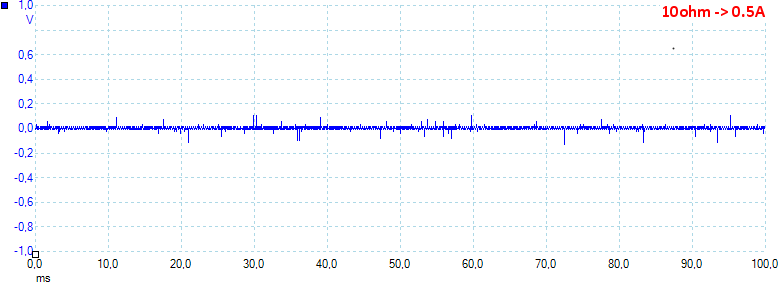
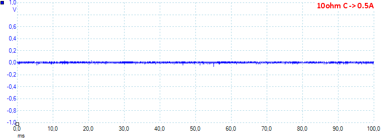
At 0.5A the noise is 10mV rms and 268mVpp.
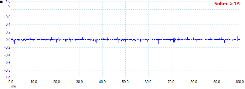
At 1A the noise is 10mV rms and 257mVpp.
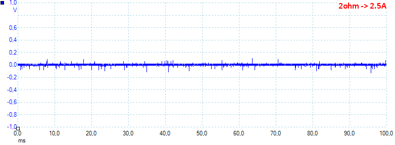
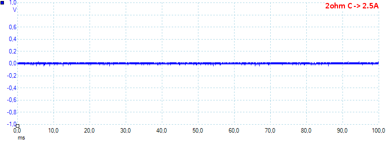
At 2.5A the noise is 10mV rms and 238mVpp.
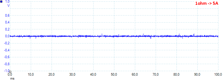
At 5A the noise is 10mV rms and 172mVpp.
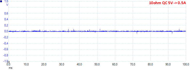
At 0.5A the noise is 14mV rms and 275mVpp.
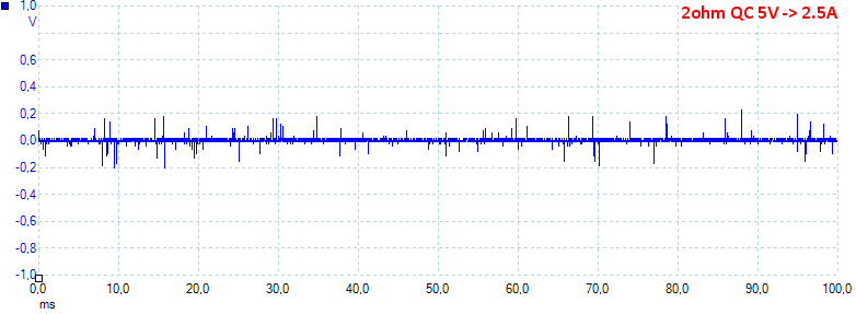
At 2.5A the noise is 6mV rms and 86mVpp.
At 0.5A the noise is 6mV rms and 170mVpp.
At 2.5A the noise is 14mV rms and 266mVpp.
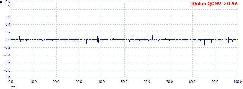
At 0.9A the noise is 11mV rms and 271mVpp.
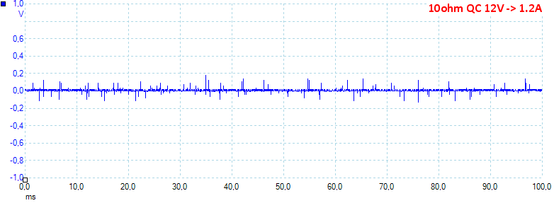
At 1.2A the noise is 9mV rms and 303mVpp.
Tear down
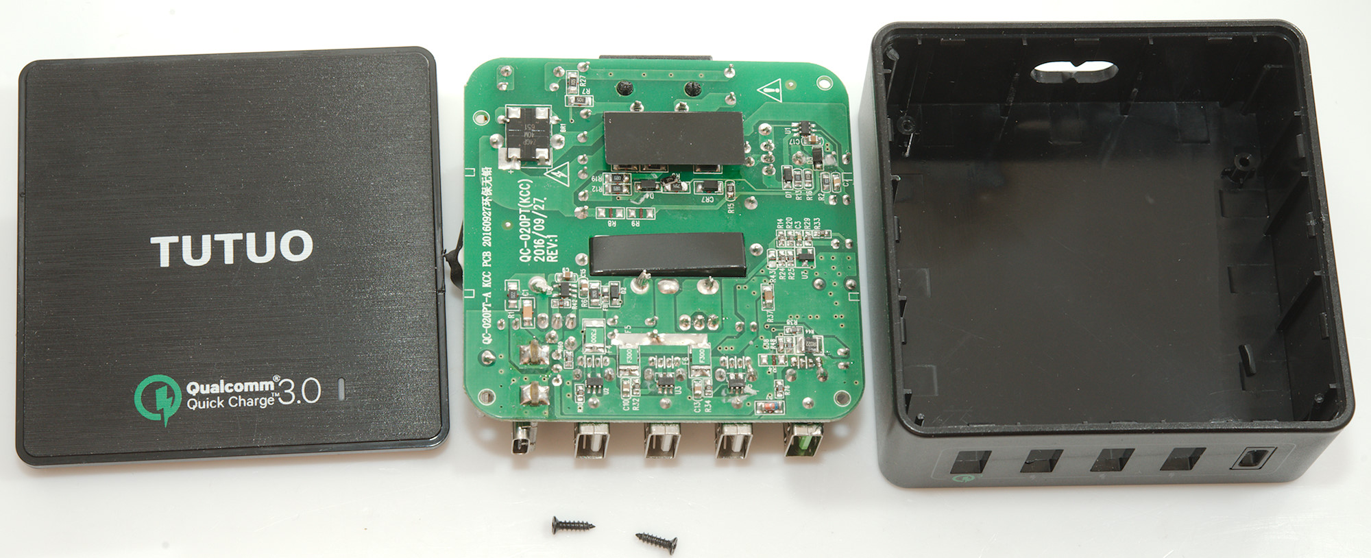
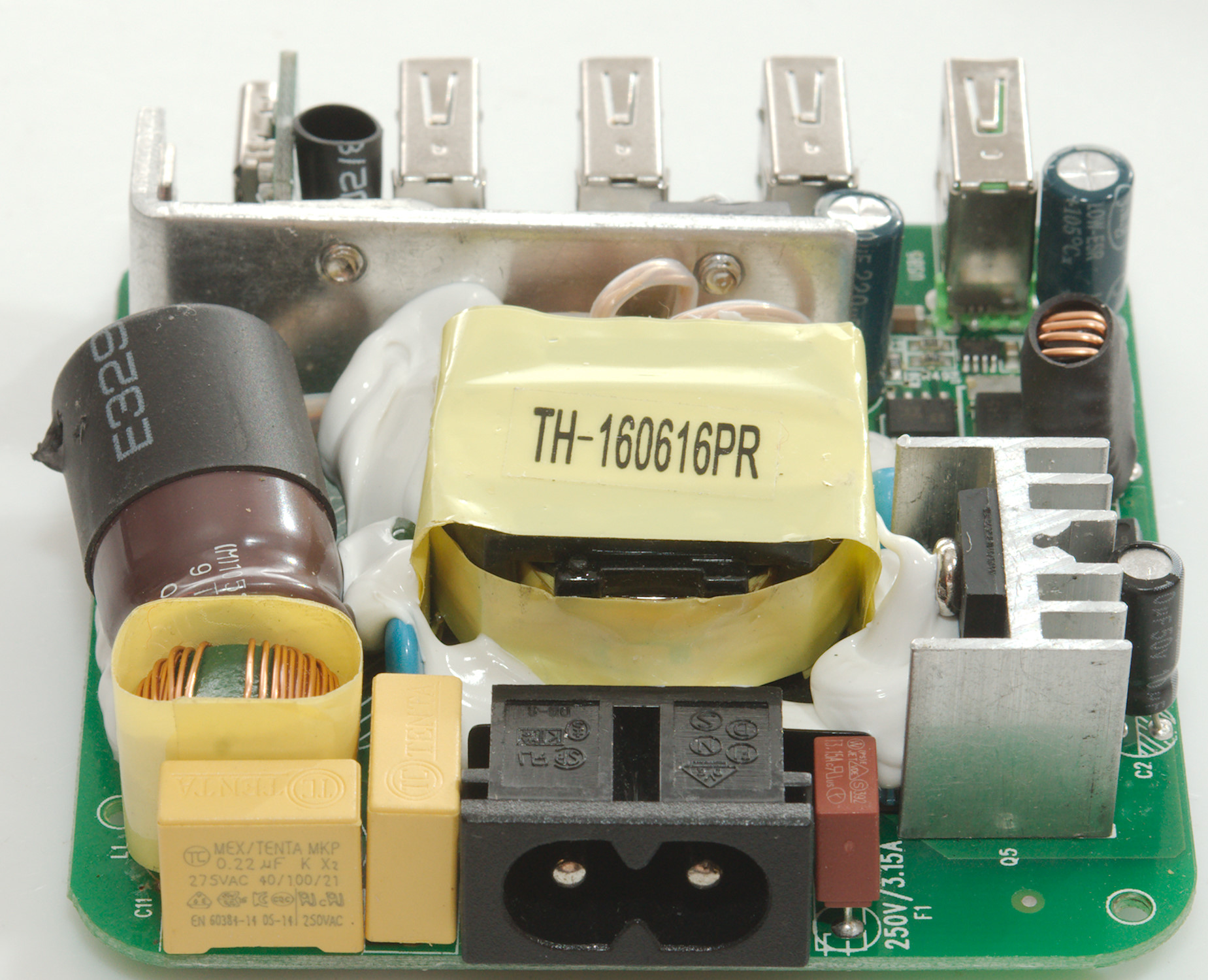
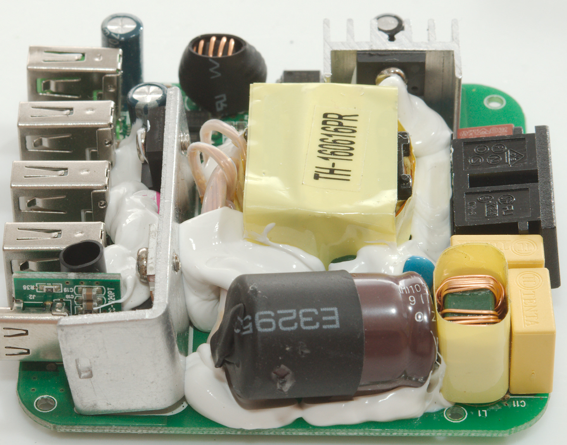
I could pry the lid of with a screwdriver, the circuit board was mounted with two screws (There was space for four).
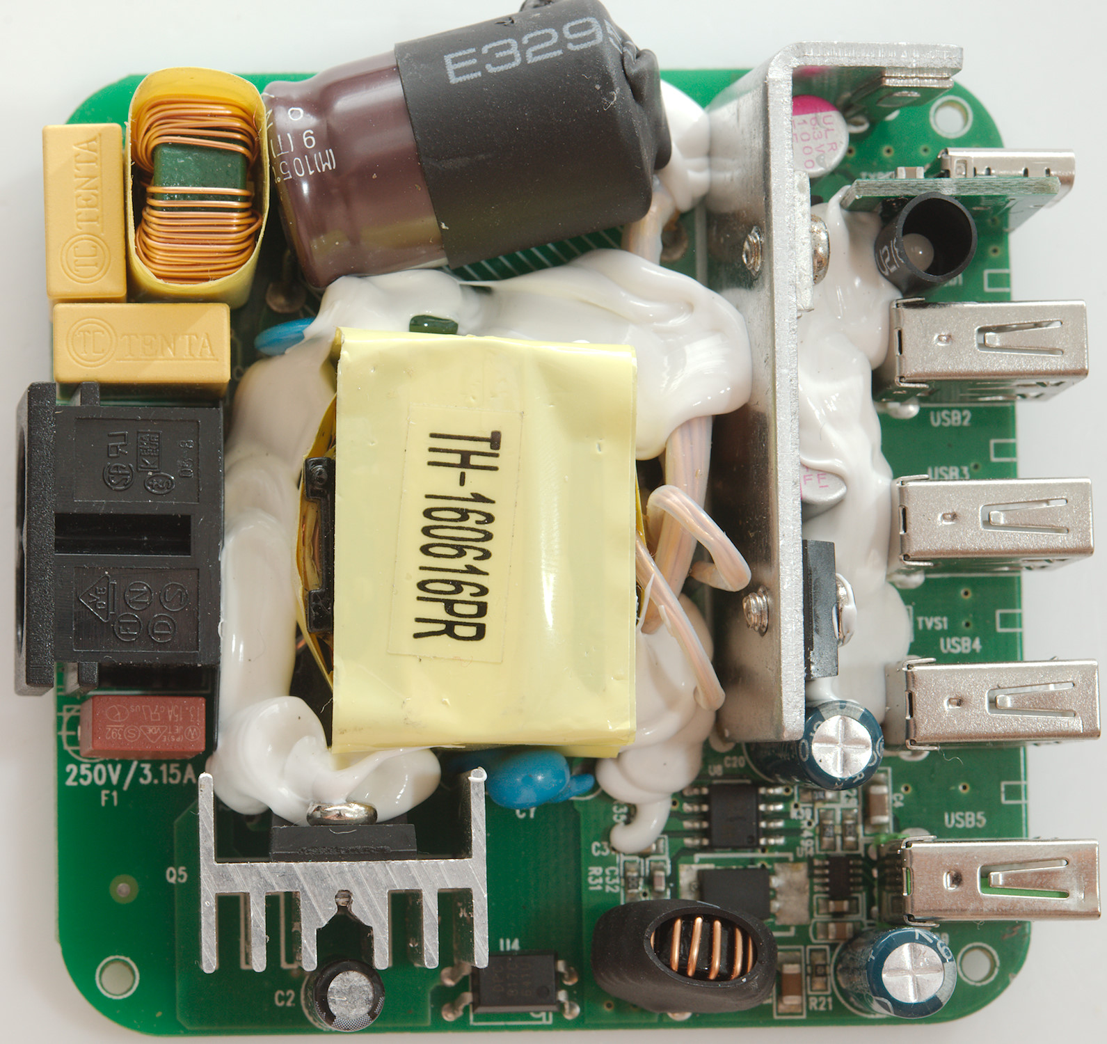
At the mains input is a fuse and a common mode coil, the mains switcher transistor is mounted on a heatsink. On each side of the the transformer there is a safety capacitor (Only one is visible).
On the low volt side is a heatsink with a diode for QC and a rectifier transistor for 5V (Both QC and USB), there is also opto feedback from the 5V rail.
The QC circuit has a inductor (L2) and a buck controller (U8?) with a rectifier diode (D5), the QC protocol is handled by a small 8 pin IC (U14?). The Power supply for QC is 5V + 9V from an extra winding on the transformer.
Next to the usb-c connector is a led in a shrink wrap tube.
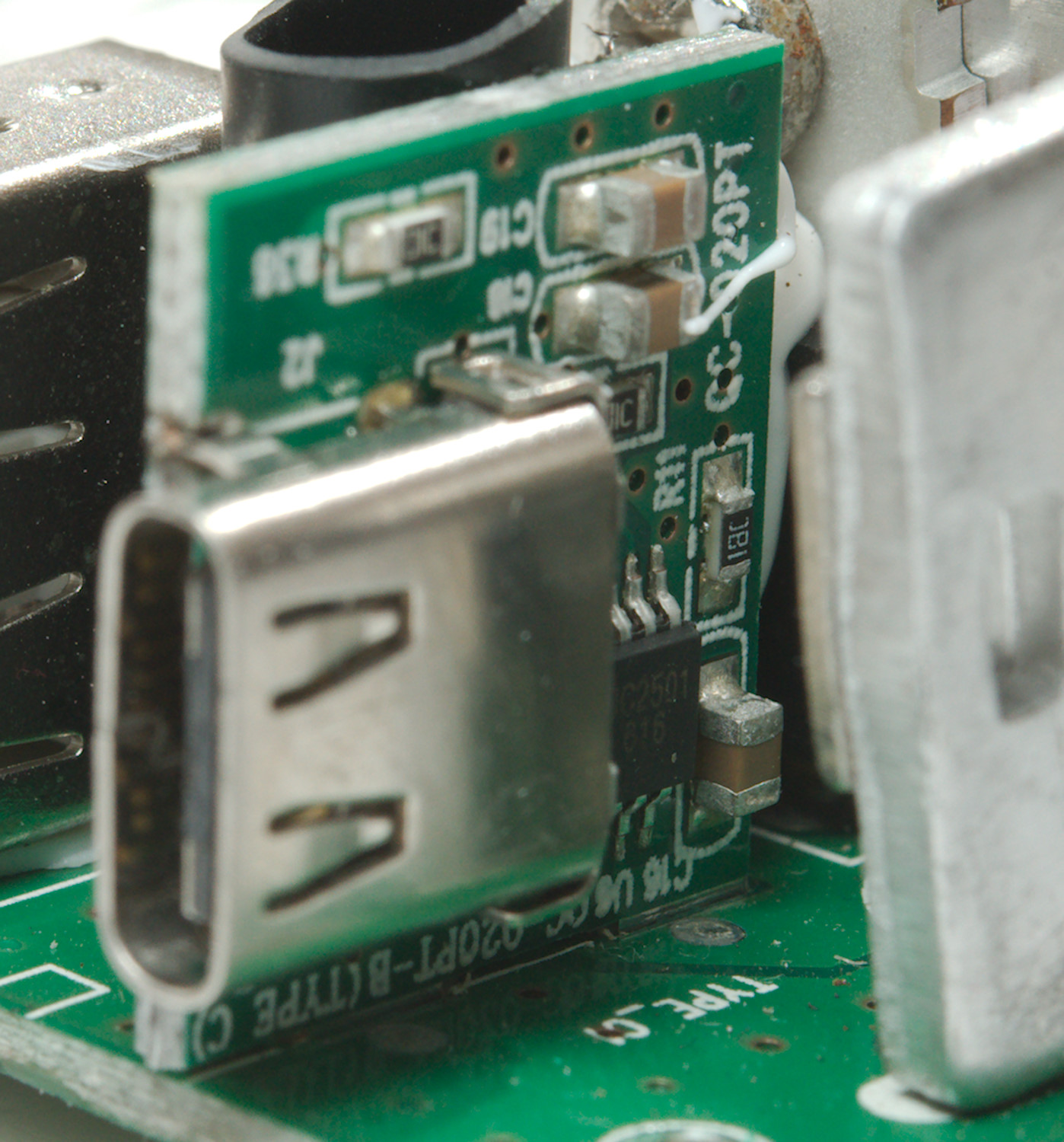
The usb-c connector has its own circuit board with a chip on it (U6: UC2501), not to implement the PD protocol, but to make it auto coding for old-style usb power and provide over current limit.

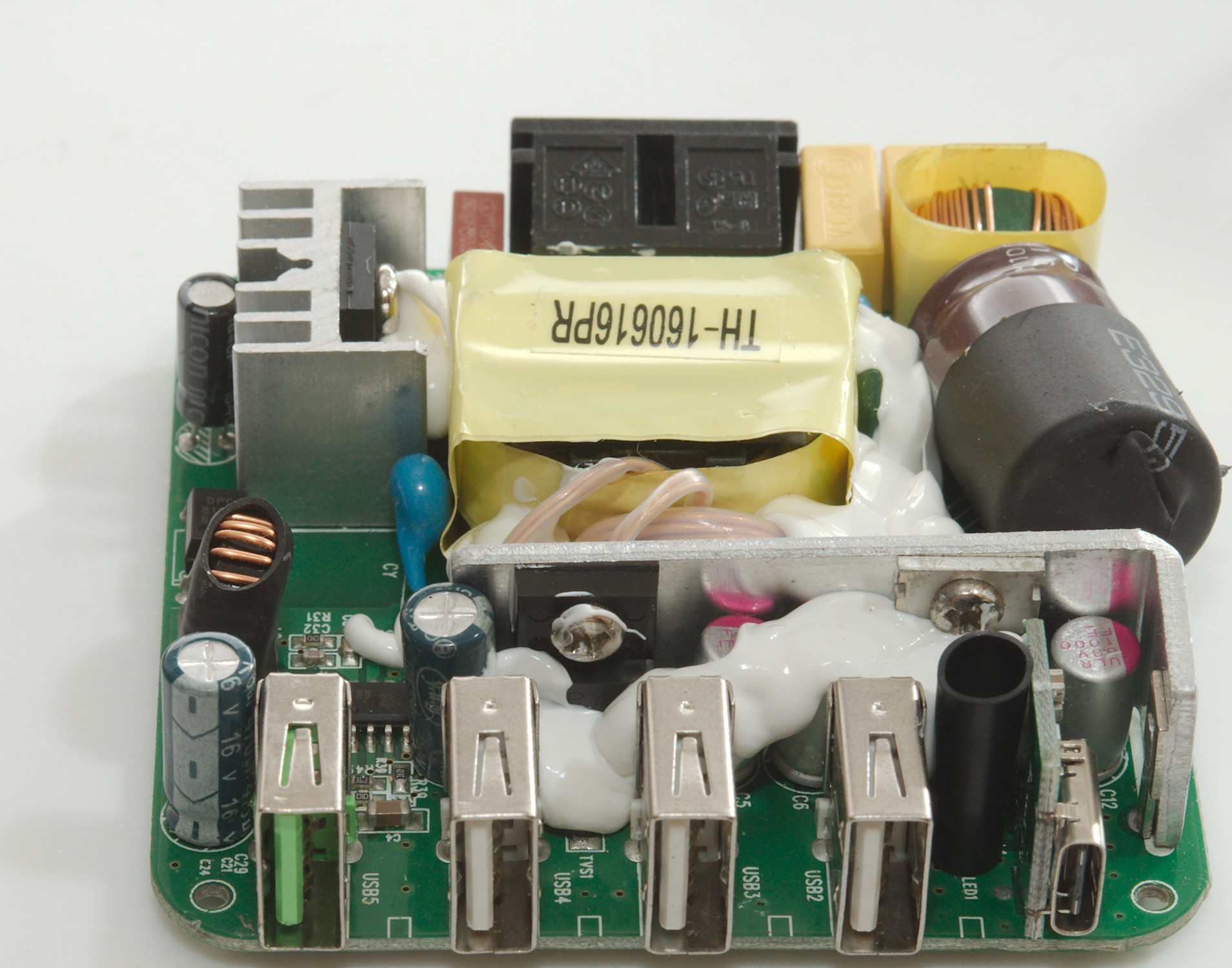

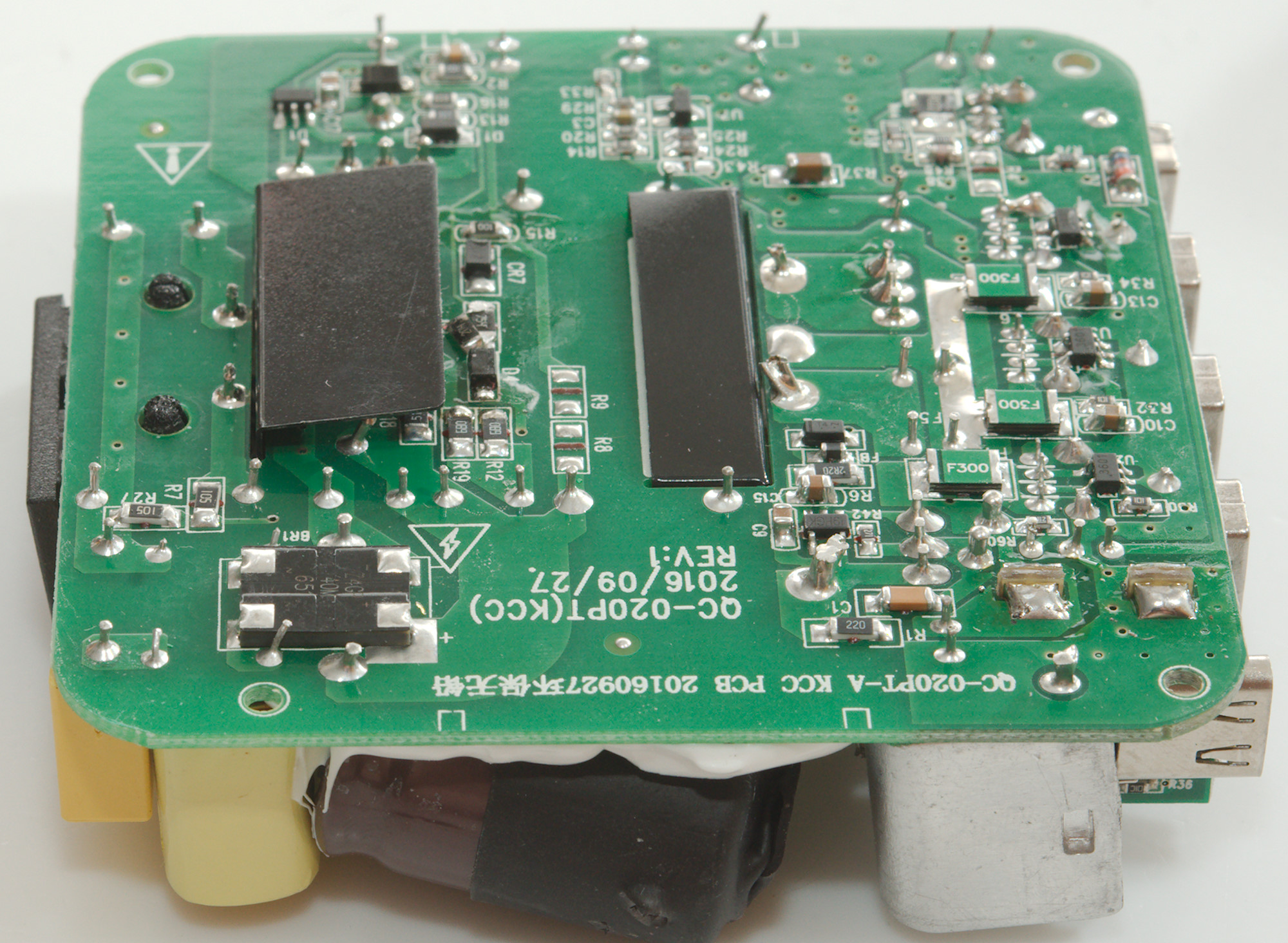
This side has a lot more chips on it and the mains bridge rectifier (BR1), the mains switcher is U1. It looks like R5 was supposed to be two resistors on top of each other, but the topmost one got loose due to heat (May have been during my test). The two black pieces are to improve mains isolation.
On the low volt side is a synchronous rectifier chip (U12) that controls the transistor on the heatsink, the voltage reference (U7: 431). Each of the regular usb connectors has a auto code chip (U2, U3, U5), there is also a regular fuse for each usb output (F4, F5, F6).
A Zener diode (D7: around 6.3V) and resistor (R76) is used for the red led.

The distance between mains and low voltage is fine.
Testing with 2830 volt and 4242 volt between mains and low volt side, did not show any safety problems.
Conclusion
The charger can deliver a lot of power and has output for the most common standards: USB, QC, USB-C.
The USB-C is not a PD with multiple voltage and electronic reporting, but just 5V. All ports has auto coding for the usual usb protocols. All ports shares a common power source and there is not enough to run all ports at there rated current, even though there is a lot of power. The noise is on the low side.
I do not like the fuses, the will protect against damaged usb cables, but it means that the usb port is permanently dead. The misplaced resistor is also very bad, I did run the charger a bit hard, but I would not expect parts to come loose.
I will rate is as fairly good.
Notes
Index of all tested USB power supplies/chargers
Read more about how I test USB power supplies/charger
How does a usb charger work?