Multimeter protection and safety
This is the second part of my multimeter design articles and it is about how a multimeter is protected for everyday use, where uses make mistakes and values are not what is expected.
For information about general multimeter design see: Multimeter design
Contents
Voltage
mV/Frequency/Temperature
Ohm/Continuity/Diode/Capacity
Current
CAT ratings
Conclusion
Voltage
What must the meter handle in voltage? The most obvious thing is higher voltage than selected range, this happens all the time on a auto range meter. Then there is AC when DC is selected and vice versa. Another obvious thing is that the input resistor must be able to handle the input voltage. When used in the real world, there is also something called transients, i.e. short, but very high voltage spikes.
Lets start with the input voltage, how high is it? A meter may be rated for 1000V DC/AC, do this mean the input voltage is up to 1000V? For power calculations basically yes, but not for maximum voltage, a sinus has 1.41 times higher voltage twice each cycle. That is the reason for 1000VDC / 600V/650/700VAC specifications (This means AC & DC has about the same peak voltage). The input resistor must be able to handle the 1000V or maybe 1500V, they are a bit hard to find and rather expensive.
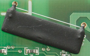
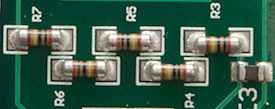
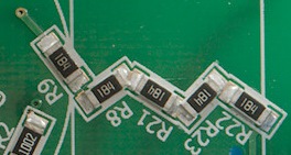
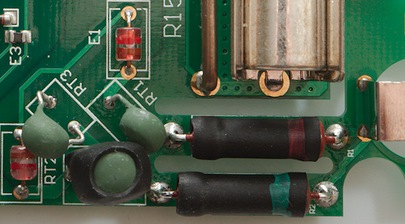
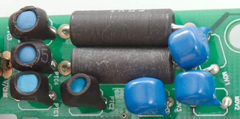
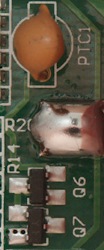
Here is two high voltage resistor, the rest does it with multiple resistors.
But what about the chip, will it get 1000V or 1500V on its input pin when in the wrong range? The answer is very simple: Most chips include some protection on the input pins that can handle a few mA without damaging the chip. With a 10Mohm resistor 1500V input will at maximum give a current of 0.15mA, this can be easily handled by the chip and the resistor only needs to handle 0.1 Watt at 1000V, this is also easily done.
Basically a meter do not need any extra protection to handle 1000V DC/AC as long as the 10Mohm input resistor can handle it.
In the real world there is also transients, a meter rated CAT III 1000V must be able to handle 8000V for a short time, this is only 0.8mA with the above resistor and the multimeter chip will not have problems with it, but the chain of resistors may not be able to handle the voltage. There may also be an issue with the range switch and 8000V, sparks jumping around in the range switch is not a good idea.
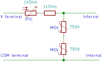
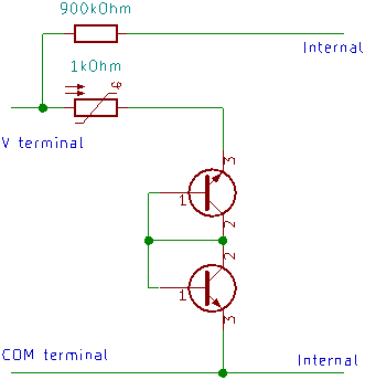
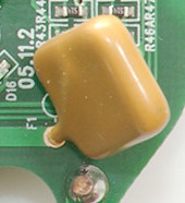
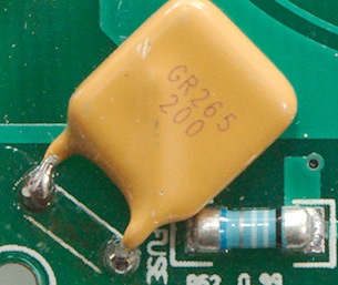
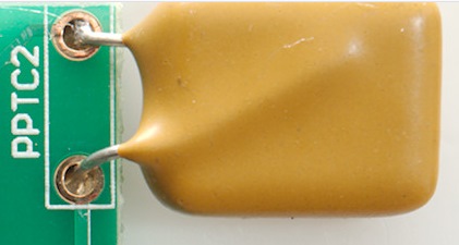
To keep the input voltage limited meters uses this circuit, the resistor and PTC values may vary a little but is about 1kOhm (Some meters may use two PTC’s in series without the resistor and cheaper meters may leave out the 1kOhm resistor). The two MOV’s will keep the maximum voltage limited (Their voltage will also vary, depending on meter) and if the high voltage pulse is long the PTC will increase resistance to reduce current (Some meters use spark-gabs instead of MOV’s). This mean the internal design (10Mohm resistor and range switch) must be able to handle about 2000V, then the meter is safe. On some meters the 10Mohm input resistor is not protected by this circuit and with a good resistor it do not need to be.
For photos see the “ohm” section, the above is only half the input protection present in multimeters.
mV/Frequency/Temperature
For these measurement the meter may use the same input configuration as above, but most meters switch to another input configuration with lower input impedance, usual around 900kOhm, but some meters use other values. This works fine with low voltage, but what happens if the meter is connected to mains or higher with a 900kOhm input resistor?
At 1000V the 900kOhm means 1.1mA into the chip, this is not a issue, but what about the power in the resistor? 1000V 900kOhm is 1.1 Watt, not a hopeless amount of power, but the resistor needs some size to handle it and it also needs some size to handle 1000V.
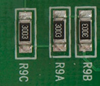
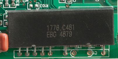
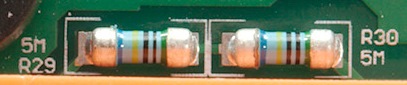
Here are two examples on the 900kOhm resistor made to handle high voltage and some power, but it is not present in that many meters. If the manufacturer want to make a good meter they often use another solution.
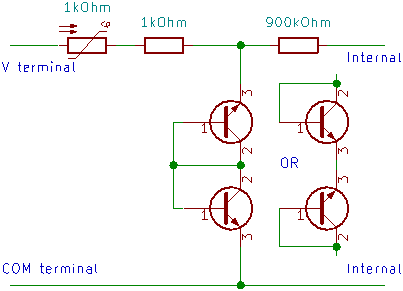
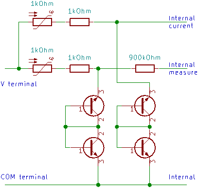
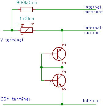
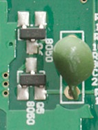
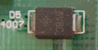
That is not a normal transistor coupling, the transistors are used as zener diodes.
Here is the voltage/current curve for one transistor (BC547), it works as a Zener diode at around 9.6V. The zener voltage will not be very precise and depend on the transistor used, the ones used in multimeters usual has a much lower zener voltage (The clamping is around 2.5V to 3V).
A voltage sweep on a pair show that it will drain current when voltage gets too high in either direction.
Expanded the current scale shows that there is very little leak current and much better than regular zener diodes.
Back to the circuit again. This pair means that the 900kOhm resistor will see less than 10V, this can also be used with much smaller resistor values without any problems. But what about the transistors, with 1000V input the current will be about 0.5A until the PTC warms up, many transistors can handle 0.5A for a short time. When the PTC warms the current will be much less (Steady state maximum will be below 30mA with a 1W PTC). A 8000V spike is a bit more nasty, there the peak current will be 4A.
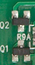
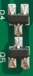
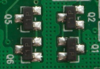
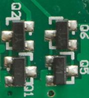
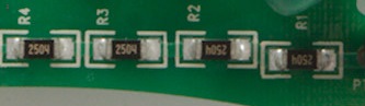
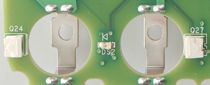
They are usual very easy to spot on the circuit board and there may be more than one pair.
The above was about the good way to secure the voltage input, the cheap multimeters do not do it that way. It is something like the above, the PTC and clamp is still connected, but the 900kOhm resistor may not be protected by it. I believe this configuration is to make the range switch as simple as possible, because it matches Ohm/Continuity/Diode/Capacity.
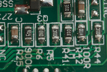
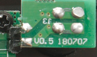
A photo of the 900kOhm or 910kOhm in this case (R25: marked 914), it is not exactly a setup that can handle high voltage or any power (The ruler is with mm ticks). It may survive 250VAC for a short while, but will not handle higher voltages or transients very well. This size resistor is typically rated for 150V! This input configuration is used in many cheap meters.
Ohm/Continuity/Diode/Capacity
In these ranges there is another problem, the meter must supply some current on the measurement terminal and this current must be high enough for reliable measure low ohmic resistors or to test LED’s, this usual means nearly a mA. At the same time it must be able to withstand that the probes is connected to some voltage, preferable mains or higher. A good meter can handle more than 1000V input in ohms range.
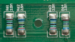
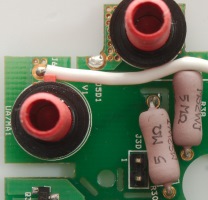
For this protection two PTC’s are needed, one for supplying the current and another for measuring the voltage, this way any loss in the PTC will not affect precision (as long as the circuit can supply enough voltage).
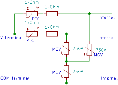
Looking at input protection there is always MOV’s on both paths, why is that? This is probably to avoid having 8000V transients inside the range switch, with the MOV’s it is limited to below 2000V. These MOV’s do not add any protection when the range is selected, there voltage is limited by the transistor pairs.
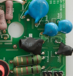
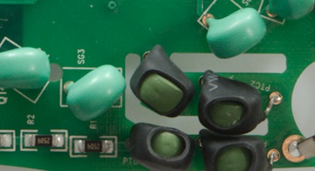
Here are some examples, one meter has replaced the 1kOhm resistors with PTC’s on two meters there is a LowZ mode with one and two PTC’s. There is also a meter where the MOV’s has been replaces by spark gabs. Note: PTC’s are usual the ones with heat shrink.
On cheap meters it is made different and much less safe. The PTC is only used on the current output and without a 1kOhm series resistor and the 900kOhm is the same as in mV/Frequency/Temperature, see above about that. The PTC is usual somewhere from 0.5kOhm to 1.5kOhm.
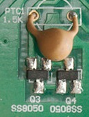
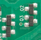
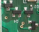
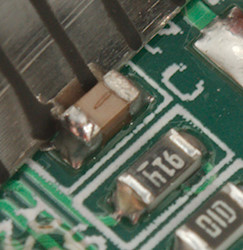
And some examples where the PTC and the transistor pair is mounted next to each other.
The above covers the best way to do protection and the bad way to do protection, there is a lot of meters that is somewhere in-between.
Current
The current inputs must be protected from smaller overloads that will damage the shunt resistors, but also for user mistakes like connecting the current range directly across mains voltage.
In current modes a fuse can be used to protect the meter, but there are some limitations.
The first one is the uA range with a 100ohm resistor, it shares fuse with the mA range. With a 0.2A fuse it means 4 watt in the resistor and what about a 0.6A range? In praxis it will be considerable more because the fuse do not blow exactly at rated current and not very fast either.
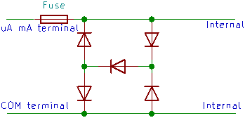
The solution is often to use a diode bridge with an extra diode in the middle to short it. This can be build with a bridge and one extra diode or with 5 diodes. This means 3 diodes is present with either polarity and will limit the voltage to a safe value for the uA shunt. This bridge usual covers both the mA and uA shunt, but not always.
In a careful meter design the diodes overload characteristic must be matches to the resistors and fuse characteristic to secure that the fuse will blow before the diodes or resistors with any overload current maybe up to 1000A.

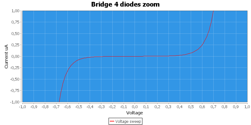
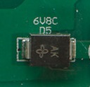
Here is a voltage sweep of a 5 diode protection bridge made with (cheap) 1N4007 diodes, it will protect the shunt from more than a few volts.
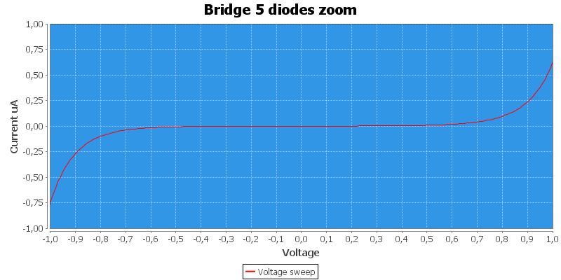
But these diode are not prefect for very low current measurement, there is a small leakage current, depending on voltage (A 6000 count meter will usual have 0.6V across the shunt when at maximum). This current is very temperature depend, i.e. the meter may loose a bit of precision in uA on a very hot day.
There is nothing saying it has to be exactly 5 diodes, it could be 6 diodes, but 4 needs a meter with very low burden voltage (Maybe a 2000 count meter). There are some meters that uses two antiparallel diodes, again they must have very low burden voltage.
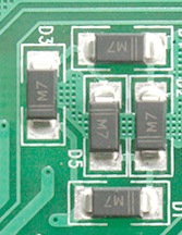
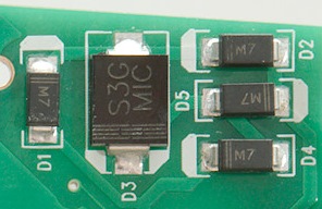
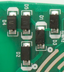
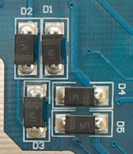
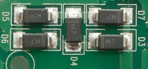
Here are some examples on the bridge coupled shunt protection, one of them with a larger diode in the centre (It must handle double of the other diodes) and one with a real diode bridge package.
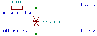
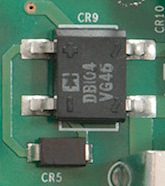
An alternate way is to use a TVS diode, this is often seen in the cheaper meters. This may work for short transients, but may not protect the uA current shunt resistor and TVS from overheating with longer time overloads.
And some examples on TVS diodes.
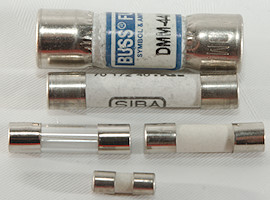
Many different sizes of fuses are used in multimeters, but not all are suitable for the job. They can all protect against a small over current when working at low voltage, but handle the user mistake of having the probe in the current plugs while trying to measure a high voltage requires much more of the fuse. The fuses are always fast types.
To handle high voltage with high current the fuse must be rated to break the same voltage as the meter is rated for and it must be able to break very high currents, this means a large ceramic HRC fuse (HRC stands for High Rupture Capacity). The is mostly interesting when working with power distribution or in industrial settings, power after a normal mains outlet is not that dangerous.
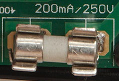
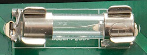
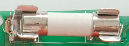
These fuses are too small (10mm & 20mm long) and will not protect the meter and user against high energy shorts, but will be fine on a bench with low voltage and also on mains as long as it has a not too large fuse.
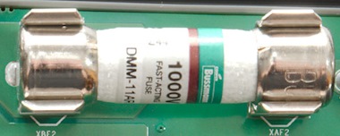
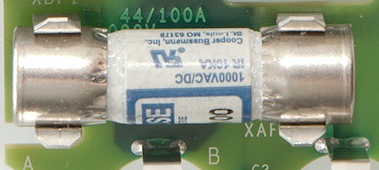
This is the high quality multimeter fuses (38mm long) that can break just about any current up to 1000V, but they are usual rather expensive and is never used in cheap meters.
Sometimes meters uses a PTC instead of a fuse for mA, this again is mostly for bench and low volt use. The nice feature is that is recovers automatic after an overload, the bad feature is that is often has higher resistance than a regular fuse, i.e. the meter will have higher burden voltage.
When a fuse is blown the current input must be able to handle high voltage, CAT ratings says twice the rated voltage. This means some distance from fuses and current terminals to other stuff in the meter, maybe slots in the circuit board and plastic shields.
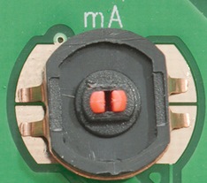
One detail is meters with sensing for a plug on the current inputs, it can be made optical, mechanical or electric with slot terminals.
A optical sense.
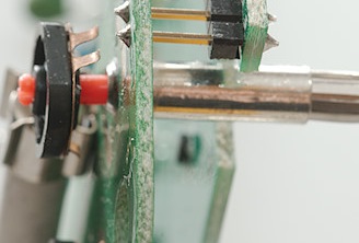
A mechanical sense.
Two electric sense systems, one with 5Mohm resistors to block any voltage/current from the rest of the multimeter. In the first sense system the meter will probably fry if the fuse blows while measuring high voltage.
CAT ratings
I have referred to CAT ratings a few times, they are standards for how large and powerful transients can be expected on mains volt in different locations. Locations are divided in for different groups (Some standards do not include CAT I), they are roughly:
-
CAT I: Electronic and other equipment after the mains transformer.
-
CAT II: Anything connected to normal household outlets.
-
CAT III: Industrial and other high current installations.
-
CAT IV: Distribution and outdoor conductors.
In addition to the location type is a voltage specification for how much the meter can handle at that type of location.
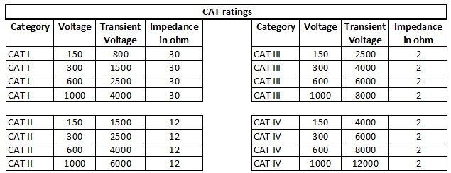
This table list the valid voltage specifications and what transient level the meter must handle when marked with that voltage. Notice that CAT III 1000V and CAT IV 600V has the same transient specifications, for this reason meters often will list both.
The CAT ratings do also have other requirements.
Conclusion
In this article I have shown how protection is typically made, but multimeter manufacturer are very creative and other solutions exist, some god and some bad.