I recently finished building an led lamp for which I had planned it to have an “standby power” led light. If you are wondering, the lamp has two drivers and a remote controlled dual relay board which controls the on/off and which AC driver is used to light up the led array. The standby power led light lits when the 12 V AC/DC supply which powers the relay control board is on. At first I used a cheap 5 mm led bought in eBay years ago, but since I heard of their very low potential lifespan (and anyway I somehow blew it while testing) I decided to use a couple XP-E2 green and XP-G3 royal blue emitters I had lying around instead, to cast some nice cyan light, on a 2S2P quad board.
In order to determine how much heatsinking power a ∅20 mm MCPCB has, I run a practical test. Took a cheap fake unused emitter on ∅20 mm aluminium board long ago removed from a flashlight, put some thermal paste over the board aside the emitter with my DMM's thermocouple on top of it, and powered it up with my DC supply:
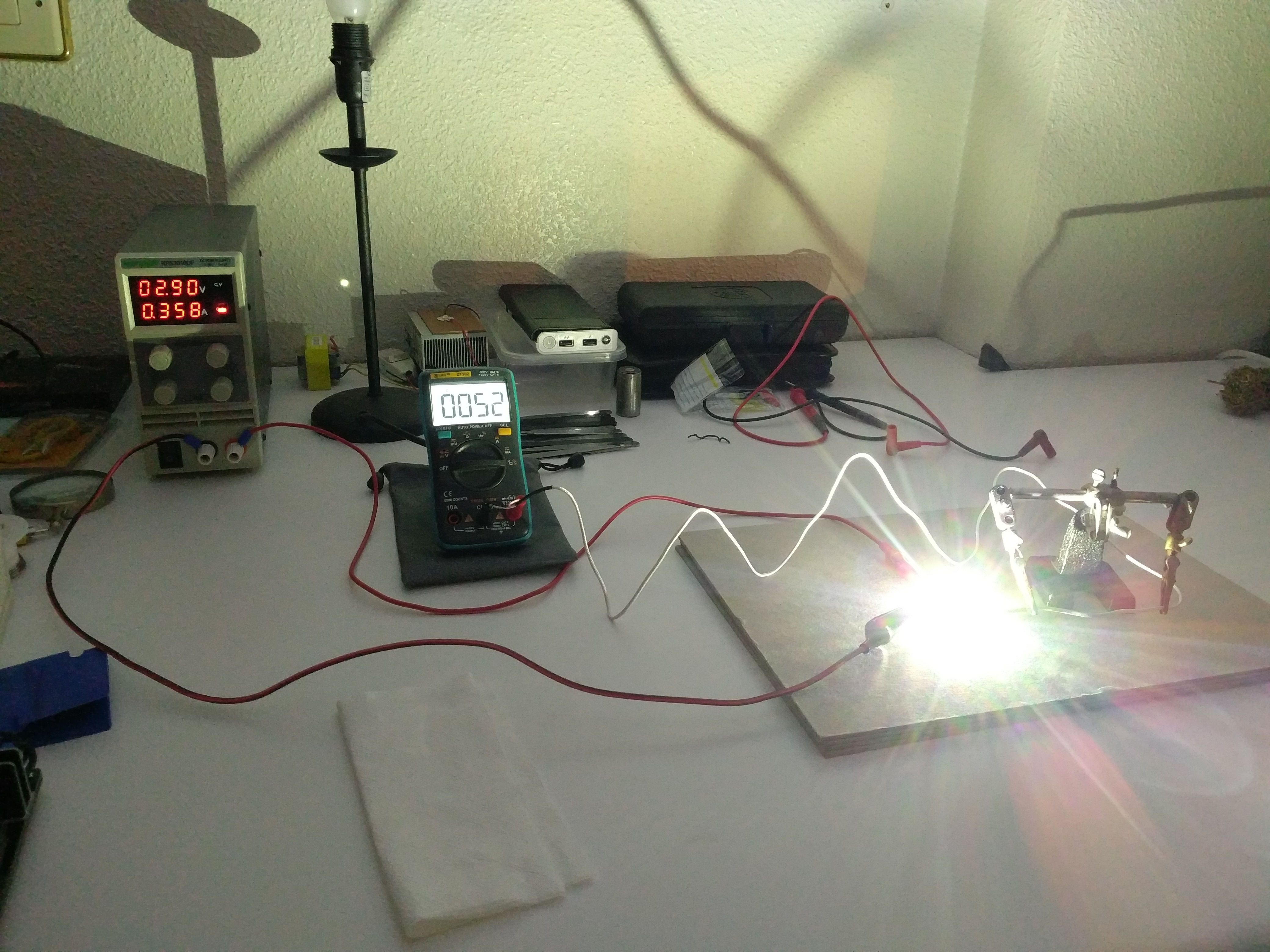
That is roughly one watt of power. Cables and connections may have ≈0.2 Ω of resistance, which is 70.8 mV of drop at 354 mA of current. So, P = ≈2.83V × 0.354A = ≈1.00182 W (my supply's amperimeter zeroes at ≈4 mA). After a nice while the MCPCB temperature stabilized at 52 °C.
But what was the room ambient temperature?
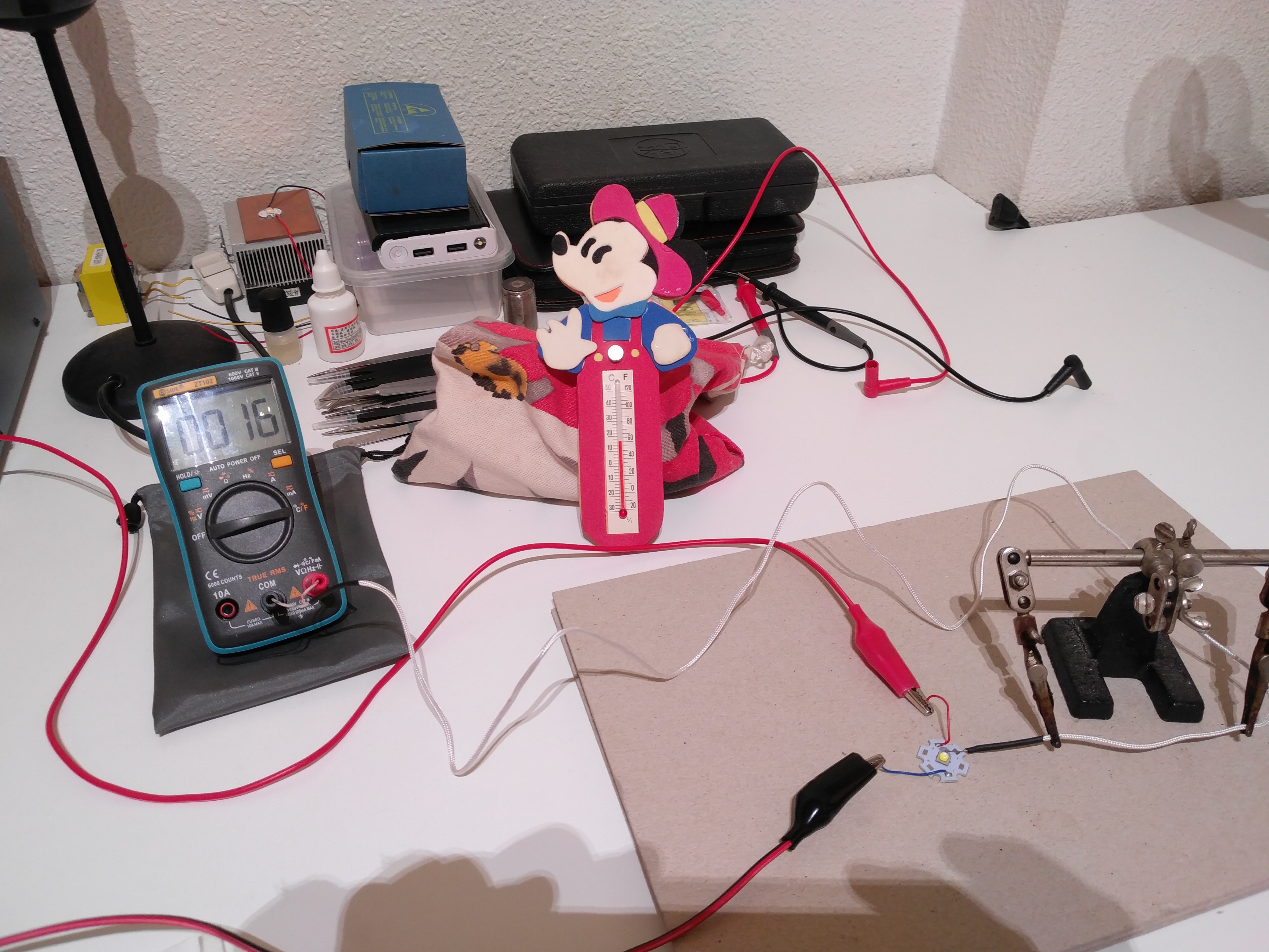
There you have it: 16 °C. I placed my good old Mickey Mouse thermometer alongside to verify my DMM's accuracy.
This means +36 °C for one watt of power, roughly speaking. Remember this is not the led die's temp, which in a conventional cheap aluminium board may be a few (?) degrees higher versus a subtle difference for copper boards.
Clemence said something about this in Testing a Cree XHP50.2 J4 3A led (#183), looks like he was about right. It also depends on how much heat you want to allow, with ≈1.5 W of power and 25 °C ambient the onboard temperature should still stay a hair below 80° C (1.5 × 36°C + 25°C = 79 °C).
Hope this is of help. :-)