Over the last few years i bought a few plasma balls on AE… and most failed after a while. The last two only worked a few hours…
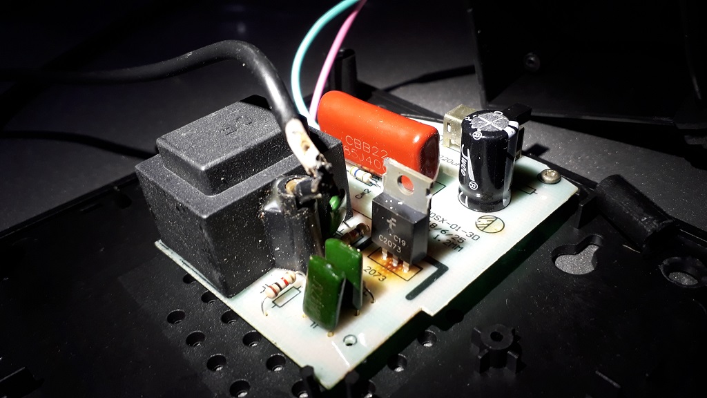
When looking inside, i notice a burnt smell and brown traces around a component that looks like a FET onto which is written C2073.
I plan to order and replace that component to see if it fixes the problem, but i have doubts about the voltage it can deal with. Over here the AC runs around 240V and it seems this transistor is only designed for 150V - not sure about that though, and maybe the voltage is lower at that stage in the circuit?
What do you think?
Is there a higher voltage equivalent for that component?
Thank you for any advise.
would you believe that the stamped heatsink now costs more to make than the high voltage power transistor that is supposed to be attached to it?
only way this kind of crap manufacturing can work is to get the contract by sending out golden samples and the bulk shipment is “cost reduced” aka cheapened.
mfr got paid,junk is being shipped on a junk,and mfr closes shop reopening under a different name and maildrop.
btw if you get a heatsink on that transistor your next failure is leakage of the globe.
those cheapies usually dont last.
the gas mixture/pressure is critical.
Was there a transformer or other board in that unit—where does the AC come in and where does it go?
Where do the pink and green wires run to/from?
Was that black wire from the big black cube broken or exposed when you opened it up? That needs to be well insulated as it is the HV output of a coil such as to fire spark plugs in a car.
The pink and green wires are the AC and they go straight into the PCB, no transformer.
The black exposed wire is the output of the HV transformer (the black cube). It’s insulation melted because the overheating transistor was bent forward and was touching that wire, that then goes up into the glass globe.
I managed to salvage that one by replacing the transistor and adding a small heat sink. I also insulated the exposed part of the HV black wire. However i failed to resurrect a second unit… Either my soldering was really crappy or there is another dead component in there.
I don’t think there is any IC or rectifier in there but i may be wrong. For what i’ve seen it’s a very very simple design. A few capacitors and resistors, the transistor, the transformer and that’s it.
I have a burned resistor on this same circuit. I’ve just send you a PM Patmurris in case you can tell me which was the ohms value of it so I can replace it.
Have you traced out this circuit and could draw a schematic? Or post a good picture of the top and bottom sides and somebody here could do it.
What is the little 4-pin chip with the white line in the upper left of your photo—is it a diode bridge rectifier chip, can you read the part number on the chip?
Is the surface of the globe connected to anything, such as to the earth ground terminal of the AC plug?
Sorry, no schematic… I’m an electronic newbie and was just looking to replace the burned resistor, as it was obviously burned, to repair the plasma ball. And i found this thread where patmurris has the exact same circuit!
@Brunola; sorry for the late reply, i was quite busy… and out of my house for the summer so i don’t have access to any plasma ball pcb at the moment. I checked whatever picture i took at the time but can’t seem to find anything that could help with this resistor value.
BTW: the one i thought i did fix apparently failed again very quickly… It was return to me after a while and is still waiting some more fixing.
Not sure this is worth the trouble, but i’d like to be able to make those plasma ball work because… well, i like them. That’s gonna take some more time i’m afraid.
[edit 6/2022: R3 was found to be 470 Ohms on a members board, which agrees with the simulation results in post #22, so just ignore the value suggested here]
This is a really cheap power supply and somewhat dangerous with no fuse or circuit protection.
From what i could calculate you could use a 1/4Watt resistor of 33 Ohms in R3. This is assuming a 240vac mains voltage and 340VDC for the DC buss.
This would put about 2.5 V at the base of the 2073 transistor, which is half of its max base voltage rating. With a base current of 50mA the collector current would be 0.5A. The 2073 is rated for 150VDC operation and 1.5A max.
i couldn’t find anything about the CF transformer.
The plasma discharges in the reduced pressure gas (partial vacuum) in the globe, then the electrons pass thru the air to return to ground, or thru your hand to charge up your body if you touch the globe. Enjoy!