This thread is build information for those interested in building my boost driver discussed here: https://budgetlightforum.com/t/-/66233
There is a lot of information here, maybe too much, but if you really are interested in building one of these the information might be of use.
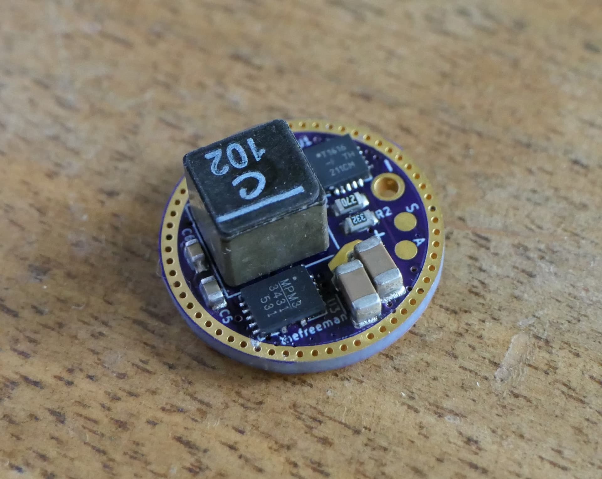
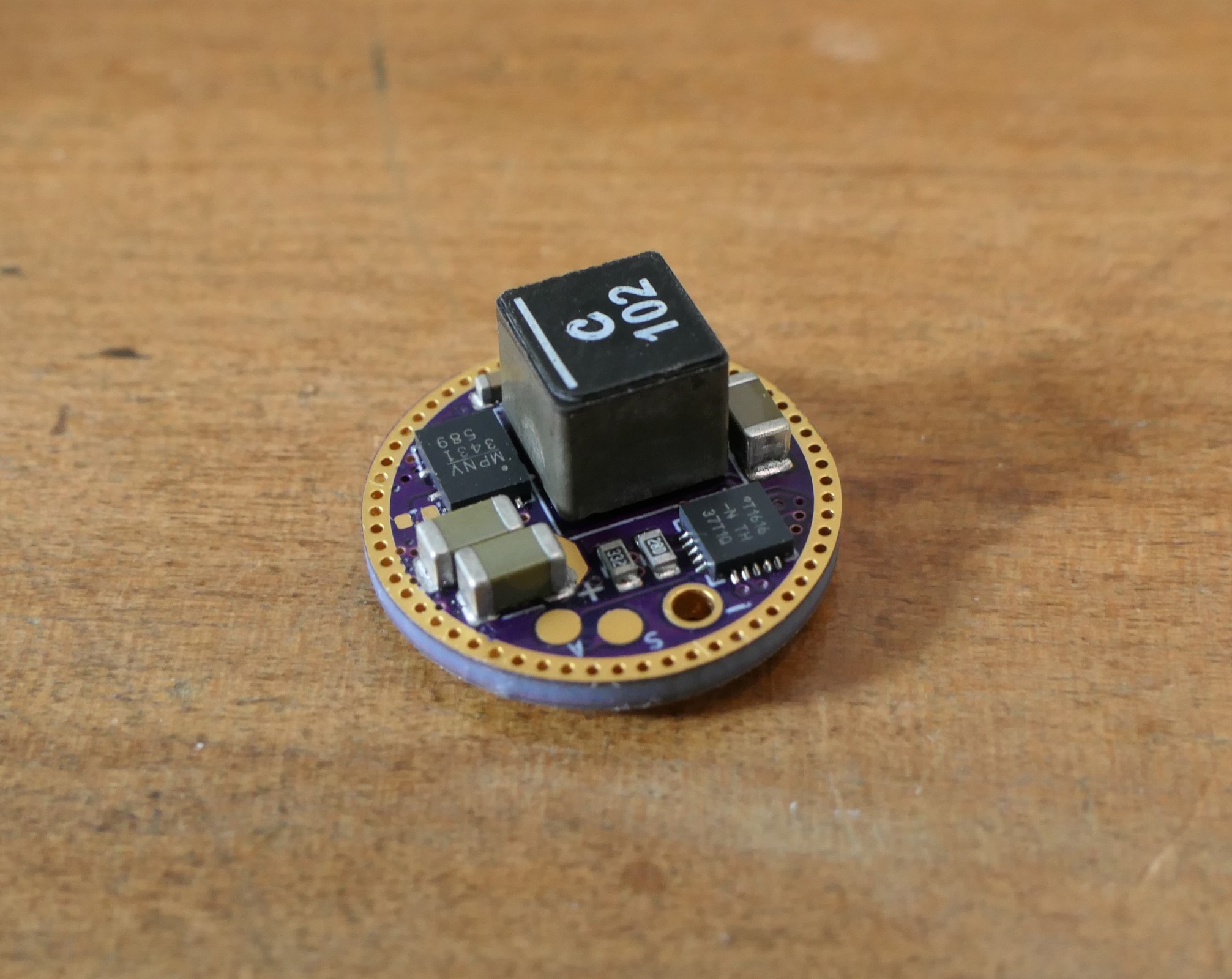
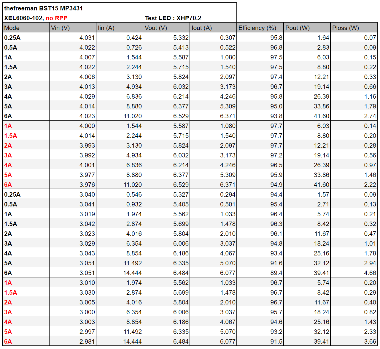
It's a 17mm boost driver capable of outputting up to 8 amps to 6 volt LEDs, in my case the XHP70.2. I have been able to get just over 9 amps to the LED but the resistors chosen for BOM have a cap on 8 amps. Resistor values can be changed to modify the hardware amp limit (more on that below). It supports E-switch, clicky switch and dual switch (one of each), and has high dynamic range which enables low moon modes (components can be omitted if HDR is not of interest).
Note: This driver does not have RVP! If the battery is connected in reverse the boost IC will fry!
The board is available on OSH Park: https://oshpark.com/shared_projects/vNVAoNDl
Firmware is not finished yet. I will make it available if someone actually builds one of these. Note that the MCU is ATtiny1616 which is which is currently out of stock all over the place. It's also a 1-series MCU which requires a different setup for programming. More information here: https://budgetlightforum.com/t/-/55911
Here is the layout and BOM:
Blue: ICs and FETs
Red: Power passives (the passives that handle the high current)
Yellow: Capacitors
Green: Resistors
Orange: Diode
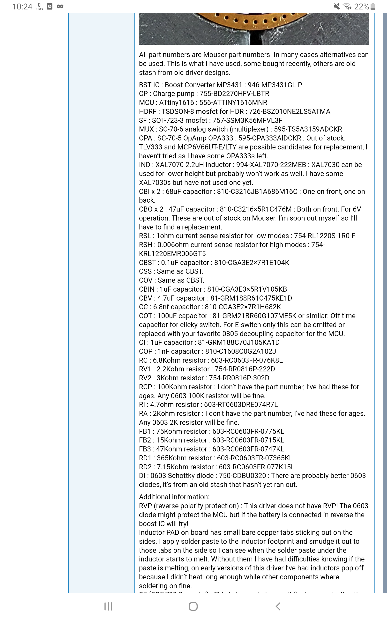
All part numbers are Mouser part numbers. In many cases alternatives can be used. This is what I have used, some bought recently, others are old stash from old driver designs.
BST IC : Boost Converter MP3431 : 946-MP3431GL-P
CP : Charge pump : 755-BD2270HFV-LBTR
MCU : ATtiny1616 : 556-ATTINY1616MNR
HDRF : TSDSON-8 mosfet for HDR : 726-BSZ010NE2LS5ATMA
SF : SOT-723-3 mosfet : 757-SSM3K56MFVL3F
MUX : SC-70-6 analog switch (multiplexer) : 595-TS5A3159ADCKR
OPA : SC-70-5 OpAmp OPA333 : 595-OPA333AIDCKR : Out of stock. TLV333 and MCP6V66UT-E/LTY are possible candidates for replacement, I haven't tried as I have some OPA333s left.
IND : XAL7070 2.2uH inductor : 994-XAL7070-222MEB : XAL7030 can be used for lower height but probably won't work as well. I have some XAL7030s but have not used one yet.
CBI x 2 : 68uF capacitor : 810-C3216JB1A686M16C : One on front, one on back.
CBO x 2 : 47uF capacitor : 810-C3216X5R1C476M : Both on front. For 6V operation. These are out of stock on Mouser. I'm soon out myself so I'll have to find a replacement.
RSL : 1ohm current sense resistor for low modes : 754-RL1220S-1R0-F
RSH : 0.006ohm current sense resistor for high modes : 754-KRL1220EMR006GT5
CBST : 0.1uF capacitor : 810-CGA3E2X7R1E104K
CSS : Same as CBST.
COV : Same as CBST.
CBIN : 1uF capacitor : 810-CGA3E3X5R1V105KB
CBV : 4.7uF capacitor : 81-GRM188R61C475KE1D
CC : 6.8nf capacitor : 810-CGA3E2X7R1H682K
COT : 100uF capacitor : 81-GRM21BR60G107ME5K or similar: Off time capacitor for clicky switch. For E-switch only this can be omitted or replaced with your favorite 0805 decoupling capacitor for the MCU.
CI : 1uF capacitor : 81-GRM188C70J105KA1D
COP : 1nF capacitor : 810-C1608C0G2A102J
RC : 6.8Kohm resistor : 603-RC0603FR-076K8L
RV1 : 2.2Kohm resistor : 754-RR0816P-222D
RV2 : 3Kohm resistor : 754-RR0816P-302D
RCP : 100Kohm resistor : I don't have the part number, I've had these for ages. Any 0603 100K resistor will be fine.
RI : 4.7ohm resistor : 603-RT0603DRE074R7L
RA : 2Kohm resistor : I don't have the part number, I've had these for ages. Any 0603 2K resistor will be fine.
FB1 : 75Kohm resistor : 603-RC0603FR-0775KL
FB2 : 15Kohm resistor : 603-RC0603FR-0715KL
FB3 : 47Kohm resistor : 603-RC0603FR-0747KL
RD1 : 365Kohm resistor : 603-RC0603FR-07365KL
RD2 : 7.15Kohm resistor : 603-RC0603FR-077K15L
DI : 0603 Schottky diode : 750-CDBU0320 : There are probably better 0603 diodes, it's from an old stash that hasn't yet ran out.
Additional information:
* RVP (reverse polarity protection) : This driver does not have RVP! The 0603 diode might protect the MCU but if the battery is connected in reverse the boost IC will fry!
* Inductor PAD on board has small bare copper tabs sticking out on the sides. I apply solder paste to the inductor footprint and smudge it out to those tabs on the side so I can see when the solder paste under the inductor starts to melt. Without them I have had difficulties knowing if the paste is melting, on early versions of this driver I've had inductors pop off because I didn't heat long enough while other components where soldering on fine.
* SF (SOT-723-3 mosfet) : This is to combat a small flash when starting the boost IC. Loneoceans was the first to report it. Most people probably wouldn't care but it annoyed me. I combat this with turning on this small mosfet with specific timing. There are other methods but so far this is what has worked the best. Those that don't care about that flash can omit this mosfet.
* HDR : Components can be omitted if low modes are not wanted. The components that can be omitted are: MUX, CP (charge pump), HDRF (HDR mosfet), RCP (charge pump pull down resistor) and RSL (current sense resistor for low modes). Then the RSH resistor must be put in RSL position. Also, when the MUX is removed the signal from sense resistor to OpAmp is broken. In the MUX footprint on the board I have added a white line between the two bottom pins. A wire or something needs to connect these two pins together so the current sense signal is carried to the OpAmp. Also, some changes will need to made to the firmware. Nothing major but I won't make these changes unless someone actually wants to build one without HDR, I will be using HDR on of these drivers I build for myself.
* RA : Aux LED resistor. I've used 2K, depends on LED and desired brightness. If an AUX LED is not used the resistor can be omitted.
* Wires : The wire connections are through hole vias as I prefer them over pads. The exception is the connection to AUX LED, I simply could not fit more through hole vias. The AUX pads are on the front side (inductor side). The pad marked A is + pad, the pad below CBV capacitor is GND pad. Two GND vias, one for programming (P), the other for E-switch (S).
* DI : The 0603 diode is not for RVP, although it acts as RVP for the MCU. It is for OTSM off time measuring for clicky switch. For E-switch only lights diode can be replaced with a 0603 0ohm jumper resistor if MCU RVP is not desired. The 100uF CAP COT is not needed for E-switch either, in that case replace with 0805 1uF decoupling capacitor and leave out CI.
* Hardware amp limit : The combination of RD1, RD2 and RSH set the amp limit. The max output from MCU pin (DAC) is 2.5V which then goes through the RD1 (365K) and RD2 (7.15K) voltage divider, and 0.048V comes out the other side. The OpAmp will then adjust the boost output so the voltage drop over the current sense resistor is the same 0.048V, and according to Ohms law that requires 8 amps. Of coarse tolerances of the resistors and other factors will prevent these numbers from being 100% accurate. One of those factors is the RSL 1ohm resistor which is in parallel, it lowers the current sense resistance a little. My latest driver build measured 8.14 amps to the LED with my cheapo clamp meter.
That's it for now, I'll probably be editing this post many times, sorry if the forum flags it as a new post each time. Let me know of any mistakes I've missed or if additional information is required.
Reserved for firmware information… I don’t anticipate that much interest, it’s not an Anduril driver, but if there are those that actually build this driver I’ll be adding firmware information then.
I have functioning firmware but it’s not ready. All functionality is tested and working though, and mode values are written in actual LED current values. For that to work the RD1, RD2 and current sense resistors are defined in firmware and used to calculate LED current. Due to tolerances and other factors it’s not 100% accurate.
A few comments (some to Mike and some to people wanting to build it)
BLF replaced your ”X”s with the cross thing.
you linked the mouser part number (stuff before the -) instead of manufacturer number, for some part there are 2 different part numbers that indicate the reel quantity, one might be available while the other isn’t, and different price. E.g OPA333AIDCKR and OPA333AIDCKT, well both are out of stock, for TLV333IDCK one have more stock.
the HDR FET is a bit expensive, Some alternatives in 3.3x3.3mm package. Maybe choosing one with a Vgs of 20V is safer, according to the mic5019 datasheet, with 4.2V in it doesn’t boost to 16V, but maybe when flashing with when powered with 5V from the xplainednano, if the driver is turned on it could blow the gate (mic5019 internal zener has a max of 19V) ? Unlikely case maybe.
input and output caps can be the same for lower cost and simplicity, the 68uF on doesn’t have that much more capacitance and the 47uF has slightly lower impedance at 600kHz, plus 2 input cap is plenty already.
Cheaper parts can be found , some with larger capacitance at 6V bias can have larger physical tolerance, That one for example
(~20uF at 6V) with +–0.3mm, need to check if that fits, the output caps needs to be >16V for 12V led of course, it may be simpler to recomend 16V caps for all cases.
some resistances could maybe be of the same value for simplicity, for example RD2 could be 3K, 2.2K or 6.8K, with an appropriate RD1, some resistance are not in stock : any 1% 200ppm or less, 0603 resistor will do, usually Bourns and Yageo are the cheapest.
mouser is expecting 82 attiny1616 for July 17, Farnell 6000 for July 28, digikey 1545 for June 25, the numbers usually decrease pretty fast, pre order now if you want to build this driver this year, don’t wait for them to be in stock.
Good suggestion, I’ll add manufacturer number later.
I don’t use the MIC5019 because I don’t like dealing with the package. I use BD2270HFV-LB instead, it boosts to 13V from 5.5V according to datasheet. A cheaper FET could be used though.
I used same caps as Loneoceans for his GXB172, I do recall him writing somewhere about those specific capacitors. In any case the 47uF ones are out of stock so I’ll be looking for a replacement. I have a few of those 68uF caps so I might just use them all around until I run out.
That could be done but I personally I don’t think it’s worth bothering about. I’ve used the values I’ve calculated, saving by using more of the same value is just something that didn’t cross my mind.
82 is a weird number to be expecting. Are they receiving more and it’s 82 of them are not yet reserved?
Ah, that’s why the footprint was weird, good thing I haven’t finished my order yet.
More than saving here it’s more that it’s simpler to build when there are fewer different values, but yeah it’s not critical, just further optimisations.
The second one. (Similarly for farnell it’s actually 6004 5974)
That is extremly annoying. And if I switch to advanced editor I loose all of my new lines, everything is if I have written it all without pressing the enter button ever.
I figured it out… If there are numbers surrounding the X, the forum assumes I’m presenting a mathematical expression and auto replaces the X. Here I am writing the exact same X in both lines:
HEYXLL
223X112
So with simple text editor I can’t change them, they are part numbers and the forum is dead set on changing them… And by going to advanced editor I loose all new lines. Perhaps I can copy to notepad, change to advanced editor, then paste everything back… Edit: That did the trick.
Great Mike C, you squeezed lots of components in!!!
It is very nice from you explaining their funcionalities, I´ve greatly enjoyed the reading.
Thanks a lot for sharing it!!!
EDIT: Also thanks to thefreeman for pointing out alternative parts, i think lack of stock will be the biggest challenge.
Yes, it’s a tight fit for sure. And stock is a challenge indeed, I stocked up on some components before they all sold out. I don’t know how long they’ll last though.
@Mike_C did you finish the firmware for this in the end? I’m interested in building one of these 17mm boost drivers now that some of the out of stock parts are available again.
I’m particularly interested in an advanced clicky switch firmware!
@merlot: Sorry for the late reply, I don’t log in here often now days.
The basic functionality is there but I can’t say I finished it, I kind of lost interest in all of this as I was spending way too much time in front of computers because of work, it all just started to burn me out. I never really finished the firmware for any of my drivers.
I also really hated the building part of drivers, the designing and programming was fun but every driver just took so long to build and the cost of all failed driver builds just wasn’t worth the hassle for me. I looked at getting them assembled but didn’t find any solution that wasn’t crazy expensive unless you ordered like a thousand of them.
As I’m not in in here at all these days I have no idea what’s been going on. Do the thefreeman’s drivers have hardware support for clicky firmware? Would be nice if they did and you could buy them somewhere, then I wouldn’t have to build any drivers myself ever again.
Anyhow, I’ve always felt like I’ll get back into the firmware writing again someday, I have a bunch of these drivers already built so it would be nice to use them, but that day hasn’t come yet. I did a giveaway a long time ago but no one ever got their drivers because I never finished the firmware. I do feel bad about that, I always thought I just needed a short break but it’s been years now.
I don’t know if you remember our discussion but I made an 15-17+mm OTSM/e-switch dual sense boost driver a while back, simpler to build without charge pump gate driver and mux, with an added reverse polarity protection PFET. I assembled it and tested it but had some buzzing issues at full output, strange because ultimately it’s the same as my other drivers when used with e-switch, could have been a bad reflow, bad component, maybe suboptimal layout.
Anyway I didn’t try to do much troubleshooting then and I had other projects. Today I did some layout/tracks optimisations, I’ll order the boards and test, hopefully no problem then.
@Mike_C No need to feel bad about it, motivation for these things comes and goes.
@thefreeman Another very interesting driver you’ve made there. What kind of firmware does it use when used with OTSM? Does it have the high dynamic range that your other drivers do? I’d love to build some if you release the designs, or buy some if you build them
@merlot Well, to be frank, only those who where supposed to receive the drivers from my giveaway can say if it’s OK for me to not feel bad. I wouldn’t be too happy about winning something in a giveaway and then never receiving it, and I feel bad about not being true to my word. My firmware may well be operational someday but I think most of those who “won” my drivers aren’t around anymore.
@thefreeman I’m not sure I am back, just passed by because I got an email when merlot tagged me. Anyhow, if you do get around to building some drivers I’ll happily buy a few and will of coarse pay in advance to cover all your costs before you order anything on my behalf. I think your drivers might rekindle my interest in this stuff again. We canceled our apartment and went to Spain for four months to escape the Swedish winter. I did bring my firmware development stuff with me but never touched it, I was far more interested in rock climbing and road cycling over all of the fantastic cols in the region. Now back in Sweden the climbing and cycling isn’t anywhere near as engaging so maybe I can bring myself to put some time into this firmware stuff again.