Please Note
This light has a big parasitic drain, moderately high with the switch LED OFF (116 uA) or on low (180 uA), not visible in room light, and excessively, exceedingly high at 13.5 mA with the switch LED on High.
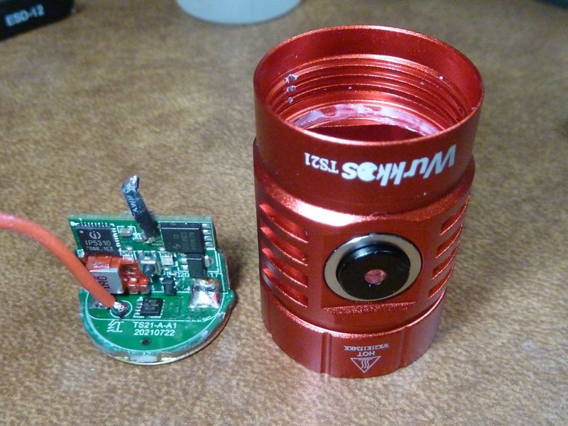
Tear Down
A brief quick tear down of the TS21, a new model from Wurkkos.
Tools used to open the TS21 - gloves to get the SS bezel unscrewed, solder pick and hammer to "gently nudge" out the driver:
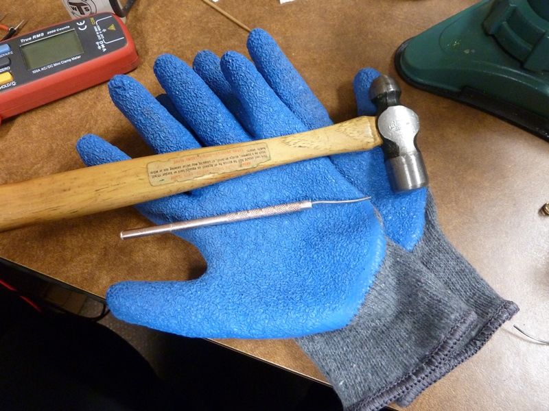
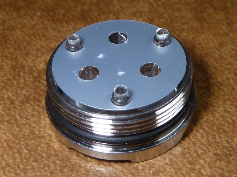
I needed the gloves because the bezel felt very tight, and it was. There's no glue but found a lot of resistance to unscrew it. As you can see, the SS bezel is surprisingly big with extra long threading:
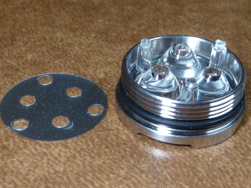
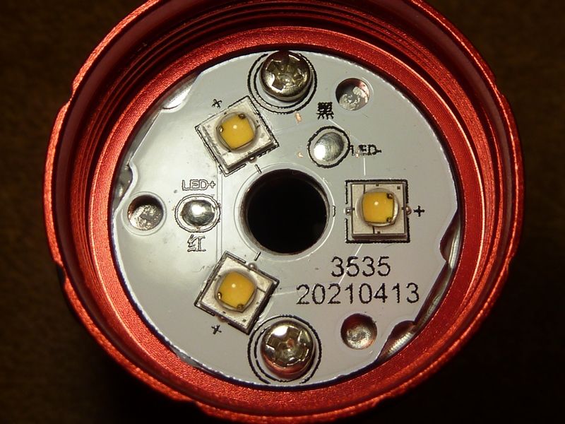
This sheet they have hides the surface of the MCPCB, not sure why, maybe effects the beam artifacts perhaps?
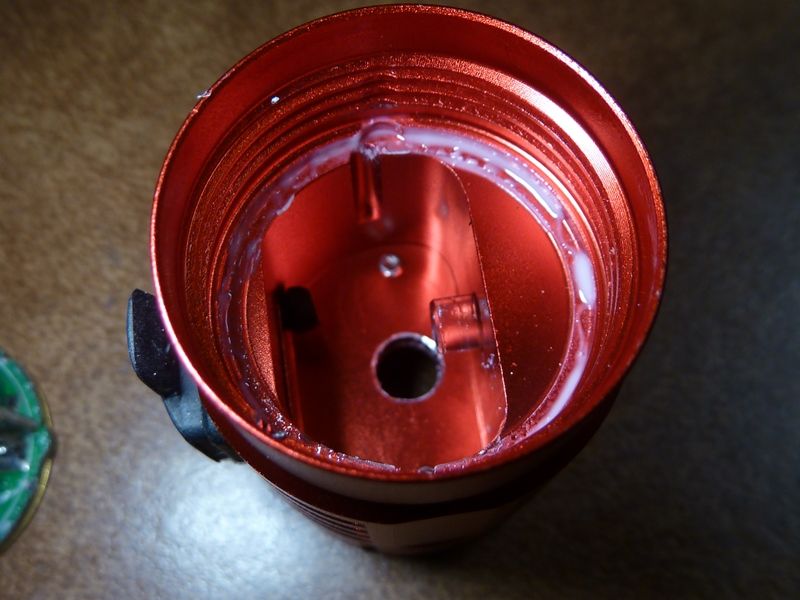
Used the solder pick with light taps of the hammer, actually not that light, to break the glue seal of the driver. Not many will have the fortitude to do it this way but I have an excellent track record of not damaging anything, or if I do (rarely), I've been able to repair it. The important thing is tilt the pick as far to the outer edge of the driver as can go - less chance of damaging components This driver has plenty of open space at the edges. Also important for this driver: you must remove the LED wires first, they are as short as possible, no extra wire that is coiled. For this light, the solder pick slipped off the driver and damaged the threads, as shown here on the left side. It had no effect on threading on the battery tube though. The glue shown here is not hard, it's soft and sticky - weird, not sure if I ever saw a glue like this, but was easily removable, cleaned up well.
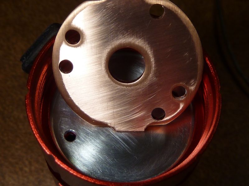
I'm guessing the shelf is about 2 mm thick, rather thin. The head by itself is very light weight, thermally there's not much here. Notice the de-burring of the wire center hole? Nice touch by manufacturing - don't see that often enough, I usually have to do it myself. The object to the right of the hole is the clear plastic tube in the center of the switch. Not sure if it's a true "light pipe" but acts as one for sure. The LED light has to bend and travel a ways in this setup, probably not the best way to do it.
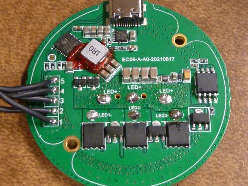
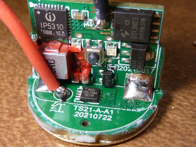
The driver - pretty much a standard FET+1 with the switch LED, same configuration as a Q8 or SP36. I'm sure they used the SP36 configuration of Anduril 2.
Showing how the red stuff partially covered one of the switch dual LED's:
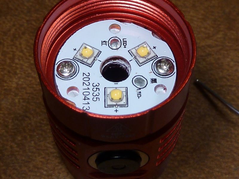
Stock setup of the MCPCB:
After sanding to 2000 GRIT, mirror finish:
Re-Installed with MX-4:
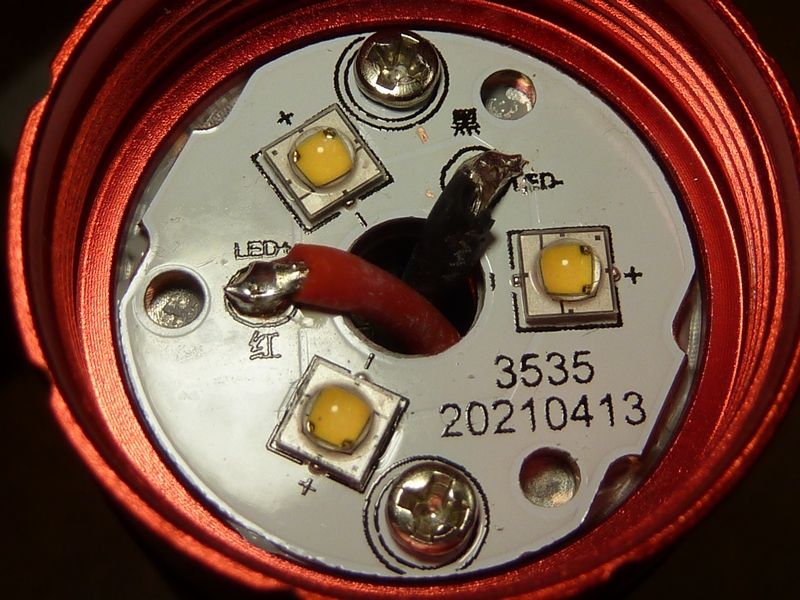
Re-using the stock wires, I'd say 20 AWG:
After assembly, no need to re-glue the driver - the screwed in battery tube will hold it in place. Now it's much easier to access for future mods or firmware updates. The MCU is easily accessible with a flashing clip.
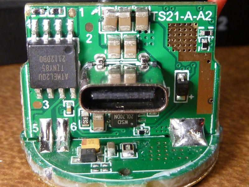
SMD Info
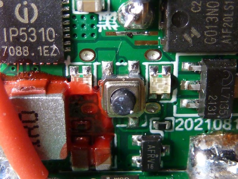
- This 3 legged SOT23 part, labeled AFRV 16, is used in the path to the amber switch LED: https://en.aliradar.com/item/4000293941721-AO3415-MOS-20VP-MOSFET-SOT23. I haven't looked into these type of parts but it appears to be a MOSFET used for voltage regulation. My questions with this part is why it's needed, and if it has any effect on parasitic drain or output of the amber LED on the low setting?
- USB-C controller is the Injoinic IP5310, datasheet PDF found here(link is external).
- The FET is the ChipSourceTek HYG013N03LS1C2, labeled: G013N03 (C2)(link is external) they are using I haven't seen before, but the specs on it look pretty good, so I'd rate it up there with the better Infineon's and Vishays we use.
Will be adding more info...
Important Note
It's difficult to recommend this light with the parasitic drain so exceptionally high with the switch LED set to High. It appears all TS21's being shipped with the amber switch LED and power bank feature have it this high drain. Of course the easy work-around is not use the high setting for the switch LED, but the low setting has very low brightness.