LED test / review - Osram OSTAR KW CSLNM1.TG / KW CSLPM1.TG (≈ 6500 K, typ. 65 CRI)

LED test / review

EN

Osram OSTAR Projection Compact KW CSLNM1.TG / KW CSLPM1.TG

KW CSLNM1.TG-5N8N-ebvF46fcbB46-15B5
KW CSLPM1.TG-8N7P-ebvF46fcbB46

For years, Osram has been offering LEDs with very high luminance and attractive pricing. Once primarily intended for the automotive and projector market, Osram's LEDs of this type are also becoming increasingly popular with flashlight manufacturers and are installed in many pocket throwers.

Technical data


CSLNM1.TG

CSLPM1.TG

Tj 25 °C - If 1,000 mA

Type: single die, domeless
Binning: 5N8N, 280 – 450 lm
Color kit: ebvF46 (≈ 6500 K)

Rated voltage: min. 2.75 V, typ. 3.00 V,max. 3.50 V
Max. forward current: 3,000 mA
Max. peak current: 3,300 mA (D = 0.5; f = 120 Hz)
Viewing angle: typ. 120°
Thermal resistance: typ. 4.1 °C/W
Max. temperature Tj: max. 150 °C

official datasheet here

Tj 25 °C - If 1,400 mA

Type: single die, domeless
Binning: 8N7P, 400 – 630 lm
Color kit: ebvF46 (≈ 6500 K)

Rated voltage: min. 2.75 V, typ. 3.00 V,max. 3.50 V
Max. forward current: 3,000 mA
Max. peak current: 3,300 mA (D = 0.5; f = 120 Hz)
Viewing angle: typ. 120°
Thermal resistance: typ. 4.1 °C/W
Max. temperature Tj: max. 150 °C

official datasheet here

First appearance

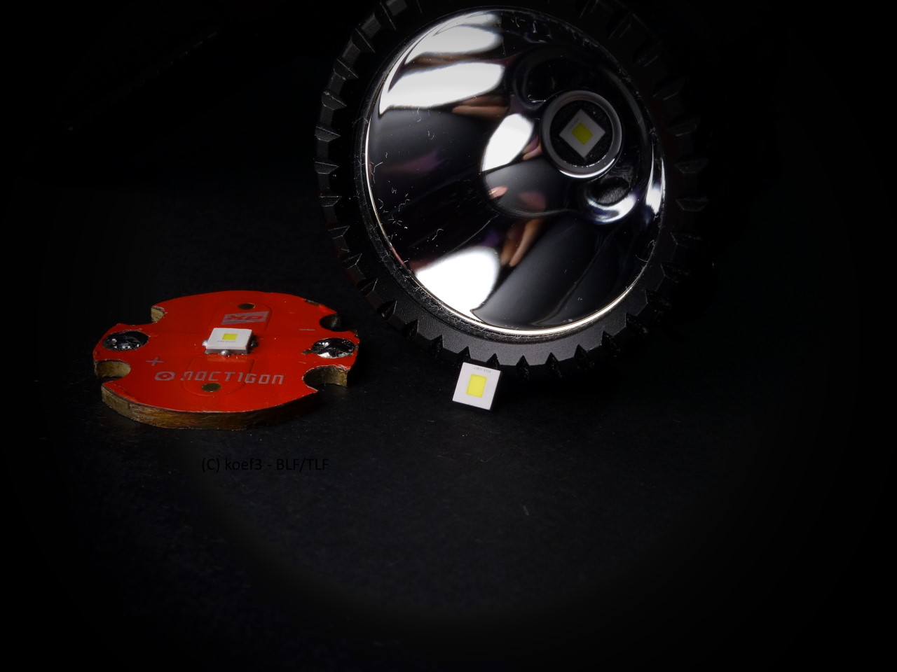
For the sake of simplicity, the CSLNM1.TG is shown on the left and the CSLPM1.TG on the right in the further course of the test. Due to the very similar construction, the description applies to both models anyway; they primarily differ in the design of the light surface.

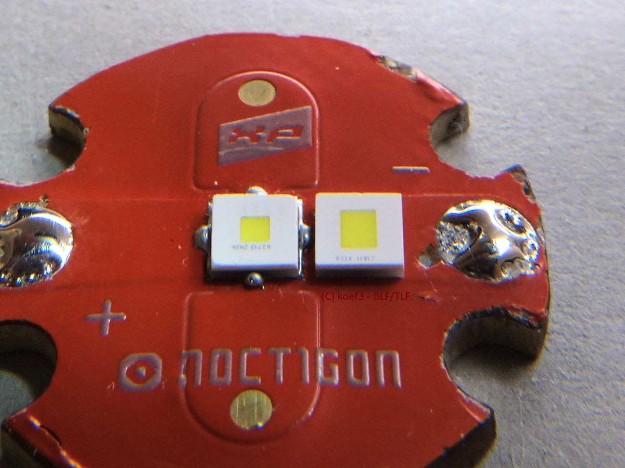
The LEDs have a white housing made of heat-resistant plastic. This is relatively brittle and breaks relatively easily, but there should be no problems with normal handling. The light area at the same height as the surrounding housing, which should minimize side light leaks. The phosphor is coated with a clear layer, protecting it from accidental damage.

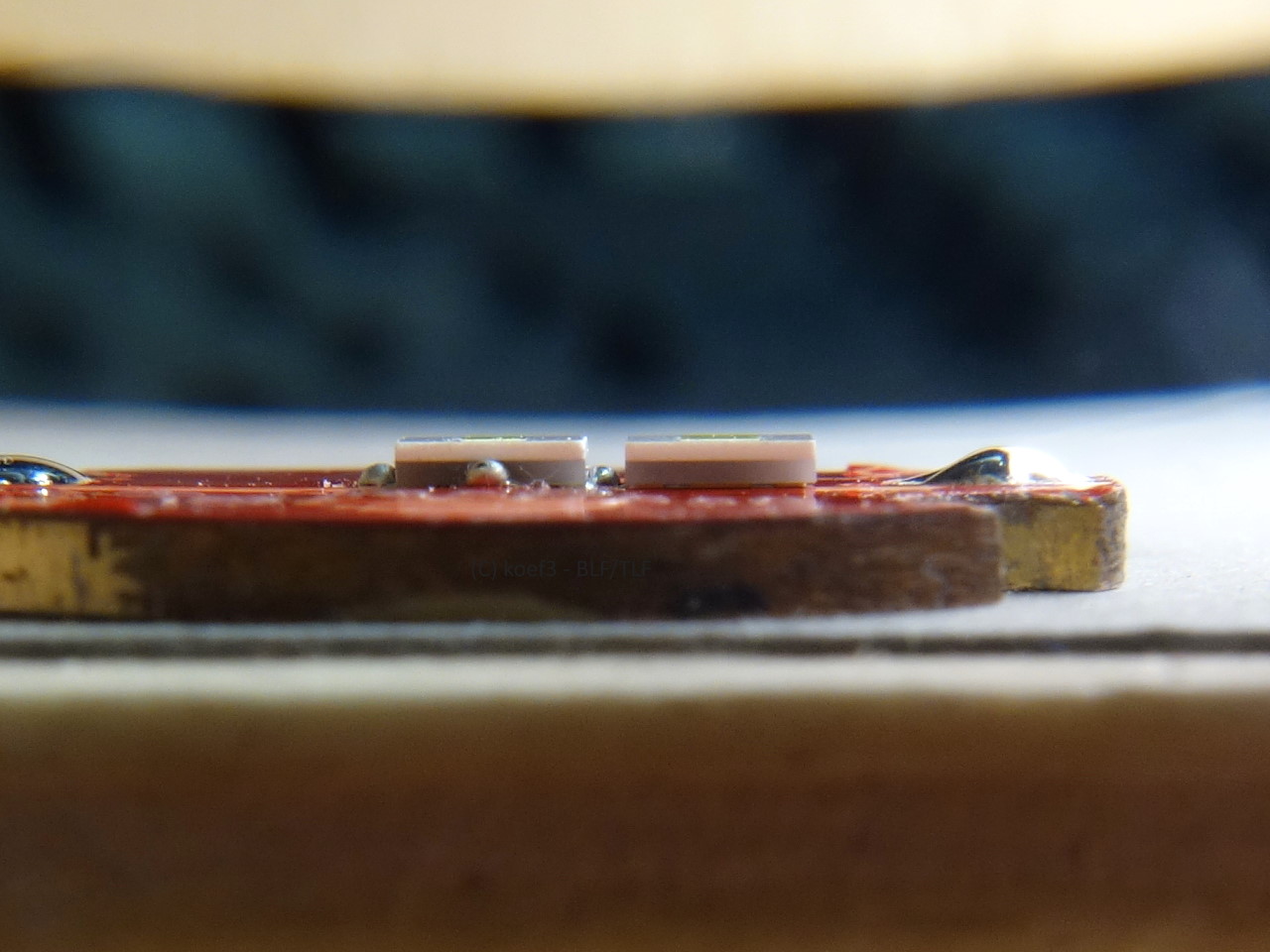
Both LEDs appear identical in the side view. Due to the missing silicone dome, they appear very flat.

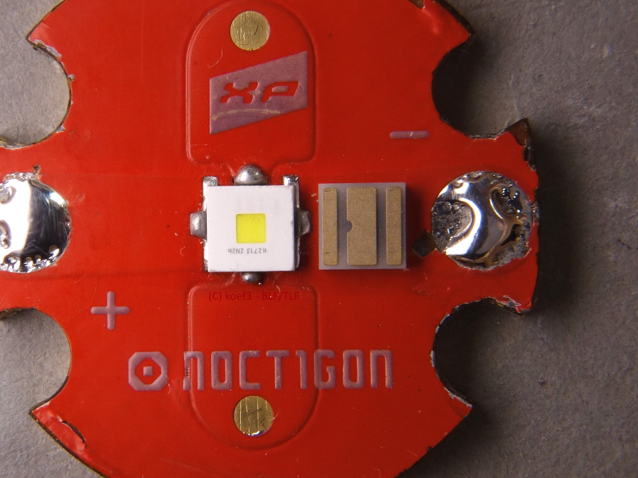
The footprint as well as the housing dimensions correspond to those of other Osram LEDs (called 3030). With existing Osram footprint and accessories this LED can be used freely. Manual soldering on boards with XP footprint (3.45 x 3.45 mm) is possible, but due to the smaller size of the thermal pad it requires high precision and is therefore not designed for automatic/machine placement. Due to the different outer dimensions, centering rings for XP LEDs cannot be used.

Due to the square base area, centering rings produced on a lathe can be used. Due to the increasing spread of flashlights with Osram emitters, an upgrade or exchange is more and more easily possible.

LED chip

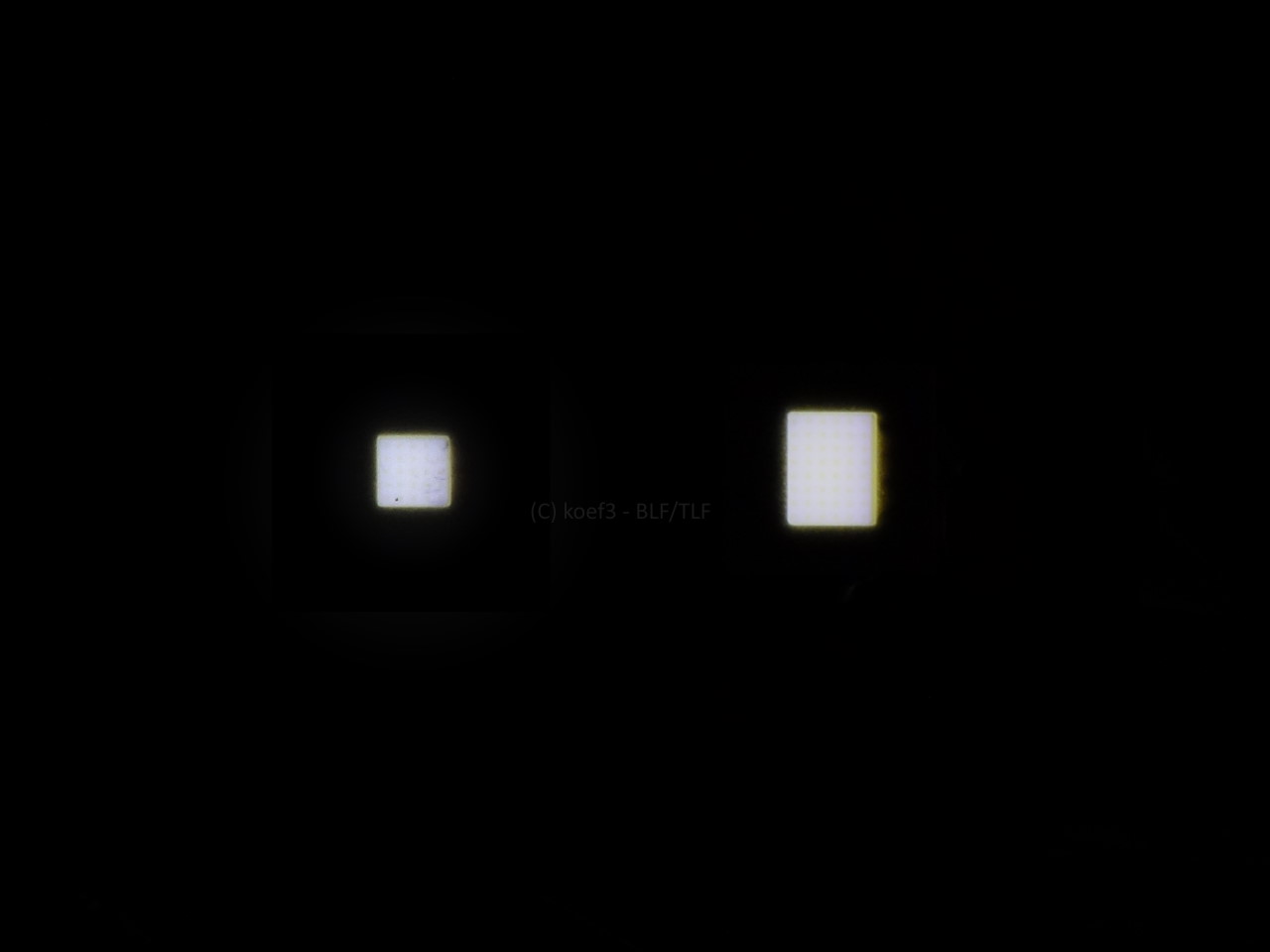
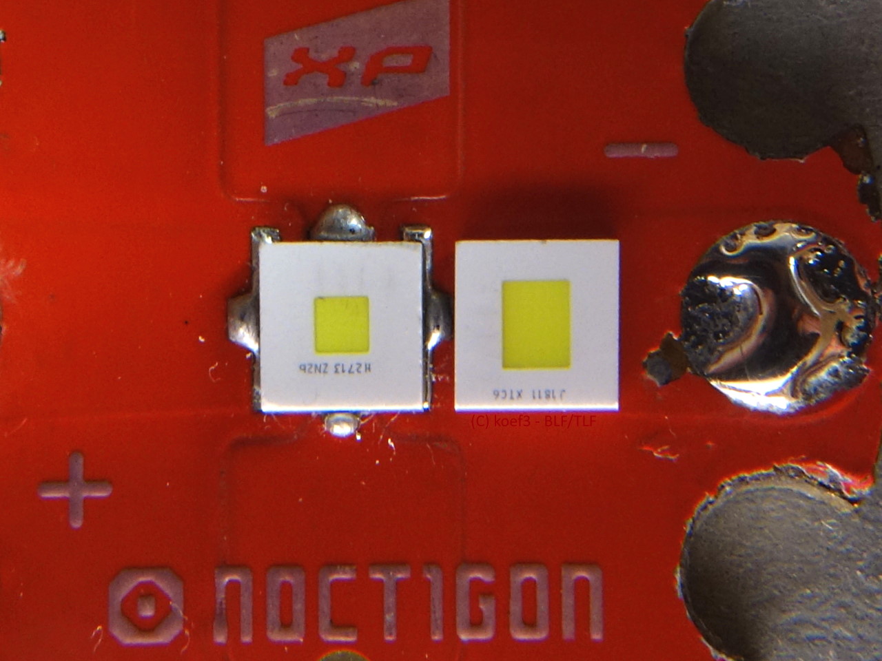
The square luminous area is 1.05 mm² (CSLNM1.TG, left) or 1.93 mm² (CSLPM1.TG, right) in size. Despite the white opaque coating around the luminous surface, there is minimal light leakage, especially with the CSLPM1.TG, which may have an impact on the maximum achievable luminance.

Interestingly, the size and rectangular arrangement of the luminous area is almost exactly the same as the LE UW Q8WP, an earlier design LED that was also manufactured without a dome. I tested this one earlier and it had very high luminance, but was significantly more difficult to handle, especially because of the electrically connected thermal pad.

The electrical parameters and thermal resistance of the CSLPM1.TG are also very similar to the Q8WP, so I suspect that Osram has reused the LED chip from the Q8WP here in a simpler package and with an electrically isolated thermal pad.

There are no cutouts for bonding wires, both LED types are manufactured in flip-chip technology.

Power and overcurrent capabilities

CSLNM1.TG

  • at 3,000 mA (official max current): 789 lm @ 3.38 V
  • Power at official max current: 10.14 W
  • Efficacy at 3,000 mA: 77.8 lm/W
  • At 1,000 mA (Binning conditions, 25 °C Tj): 350 lm @ 3.12 V – calculated to 85 °C acc. to Osram datasheet: 322 lm

In contrast to Cree, Osram only divides its LEDs very roughly into power classifications (binnings). The possible luminous flux with the above parameters can vary in the range of 280 to 450 lm. The CSLNM1.TG tested here is about in the middle of this range.

The relatively low drop in luminous flux with increasing temperature is good with these LEDs; at 85 °C Tsp, the luminous flux drops by only about 8 % compared to 25 °C.

Overcurrent:

  • Maximum reached at 5,600 mA, at this point 1032 lm @ 3.71 V
  • Power at maximum 20.78 W
  • Sweet Spot at around 3,600 mA (881 lm @ 3.46 V)
  • Power at Sweet Spot 12.5 W
  • Efficacy at maximum 49.7 lm/W
  • Efficacy at Sweet Spot 70.7 lm/W

As with the Cree XP-P, overcurrenting does bring more power, but it must be weighed in terms of benefit, since the power gain is manageable. It is obvious that Osram is already relatively generous with the maximum current. The power gain is low, which indicates limited heat dissipation, possibly also due to the footprint.

CSLPM1.TG

  • at 5,000 mA (official max current): 1212 lm @ 3.32 V
  • Power at official max current: 16.6 W
  • Efficacy at 5,000 mA: 73.0 lm/W
  • At 1,400 mA (Binning conditions, 25 °C Tj): 463 lm @ 2.95 V – calculated to 85 °C acc. to Osram datasheet: 426 lm

The electrical characteristics of the CSLPM1.TG are very similar to those of the smaller model. However, the significantly lower forward voltage is interesting here, which increases the efficiency somewhat. Due to the larger LED chip, the thermal resistance is significantly lower, which benefits the officially permitted maximum current. Osram seems to have generously designed the permissible parameters here as well.

Overcurrent:

  • Maximum reached at 8,600 mA, at this point 1499 lm @ 3.62 V
  • Power at maximum 31.1 W
  • Sweet Spot at around 5,600 mA (1296 lm @ 3.37 V)
  • Power at Sweet Spot 18.9 W
  • Efficacy at maximum 48.2 lm/W
  • Efficacy at Sweet Spot 68.6 lm/W

The low overcurrent potential is also visible with the CSLPM1.TG. Although this LED offers more overcurrent potential due to its lower thermal resistance and larger LED chip, the generous official maximum current of 5 A means that the performance gain is also less significant here and is primarily bought in with higher power consumption. If the maximum luminance is superficial, this approach may seem reasonable, otherwise the operation at the official maximum current is recommended and is also handled this way by most flashlight manufacturers.

As mentioned earlier, the LED chip is quite similar to that of the Q8WP. This is also proven by the diagram; although the maximum current differs slightly (Q8WP: 9,600 mA), the luminous fluxes are relatively close, with the forward voltage of the Q8WP being significantly lower. However, it must be noted here that the groupings in luminous flux and forward voltage are also very coarse for the CSLPM1.TG and this can also simply be due to series spread.

Luminance

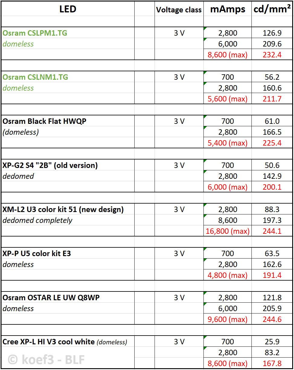
Despite the slightly translucent edge in the casing shown earlier, the luminance of both LEDs is very high. The CSLNM1.TG does not reach the value of the Black Flat HWQP, whereas the CSLPM1.TG passes thanks to its better coolable LED chip and even just overtakes the Black Flat HWQP. Although the Q8WP achieves even higher luminance, it is much harder to procure, more expensive, more difficult to handle and also requires a higher maximum current.

The CSLPM1.TG is an interesting LED for extreme throwers; however, it is important that the maximum current is reached as close as possible, which requires appropriate drivers (buck boost).

I would assume that the old well known dedomed XP-G2 S4 2B is no longer necessary since this LEDs offers higher luminance without the need of changing the emitter mechanically beforehand and at a much lower forward voltage.

Tint and light quality

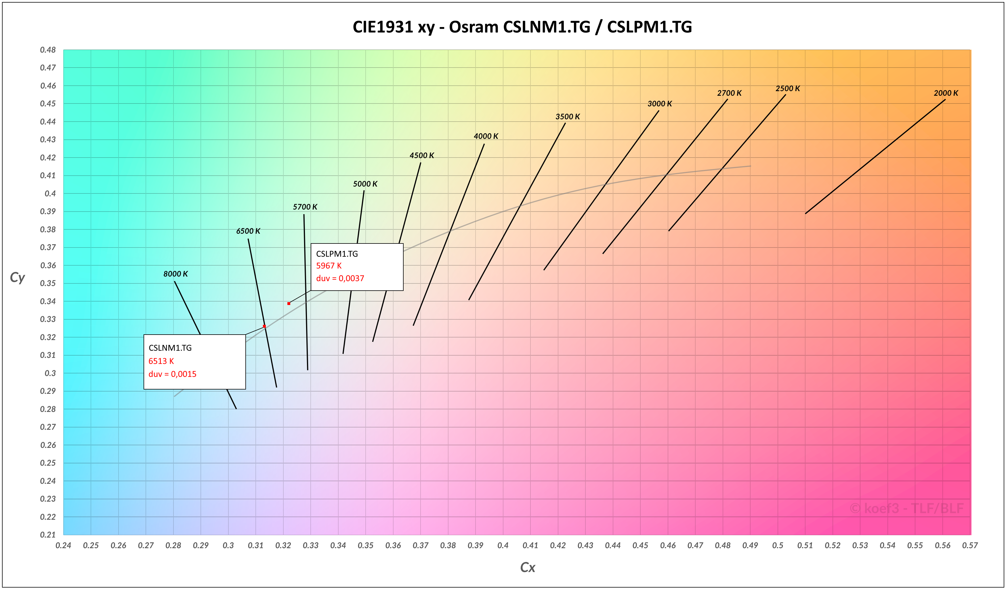
Both LEDs are sold in the color grouping ebvF46 with the highest possible color temperature (about 6500 K). According to the data sheet, other color groupings are also provided, but these emitters are not available wholesale.

These LEDs do not have coarse color casts. The spectra and measured values are typical for cool white LEDs with low color rendering. There are no conspicuous features.

For applications where high color rendition is important, these LEDs are not suitable because of their poor color rendering indexes.

Use in optics

As already known from previous flashlights available for purchase, use in secondary optics is possible without any problems. There are no color fringes or strong tint shifts.

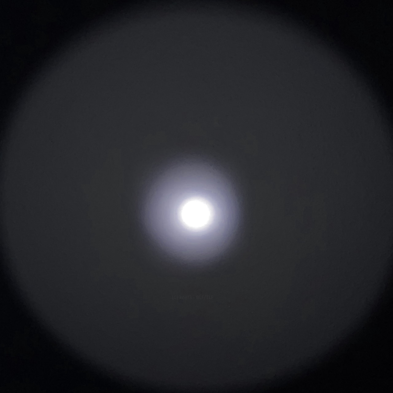
The picture shows the light image of an original Wuben E6 flashlight with CSLPM1.TG. This light image exemplifies the result of using SMO reflectors and coated glass. Despite the clearly rectangular illuminated area, the spot is clearly delineated and circular. Any rings in the spot are usually due to the quality of the reflector.

Conclusion

There are good reasons to use these two LEDs in flashlights and also for general lighting applications. The light quality in secondary optics is excellent, the light color is usually a clear cool white without strong color casts, and thanks to the electrically isolated thermal pads, use with DTP boards is now also possible without any problems. Although the overcurrent potential beyond the official maximum current is less significant, the luminance is already very high, which makes these LEDs also suitable for extreme lighting applications.

A disadvantage is the wide spread in luminous flux and voltage grouping, and the complete lack of other light colors and color rendering indices.

Pro

  • Very high luminance
  • Very good light image in optics
  • Very high luminance especially up to official maximum current
  • Attractive pricing

Neutral

  • Overcurrent is hardly worthwhile because of generous official maximum values

Contra

  • Very broad luminous flux and voltage groups
  • No other color temperatures or Ra available

Thank you for reading the test. I hope this information is helpful for everyone who wants to work with this LED type.

Greetings, Dominik

1 Thank

<reserved>

Wouldn’t the cslpm1 need over 2000lm to beat the cslnm1 in luminance?

Great testing and photos again…thank you!

For your CRI readings and chromacity graph, what drive current was used, and fair to assume it was bare without optics?

Maybe. With my measurement method (putting reflector on LED and measure the brightness in 1 m distance to calculate luminance with given LES) the values are reproducible. I assume that the LED chips Osram uses for these emitters have side LES and some light is leaking through the opaque layer around the LED chip. Maybe also the viewing angle could be also a reason for the values. In any case, the measured brightness at 1 m using a reflector like in a flashlight is indeed somewhat higher with the CSLPM1 than with the CSLNM1.

Current was 350 mA, I measured the bare LED without optics.

Ok…thank you!

Ahhh, now it makes a lot more sense! The beam isn't fully formed at this distance, with the cross-sectional area being roughly equal to the reflector opening rather than diverging proportionally to LES size. Any intensity measurements at this distance would thus greatly favor emitters with high total output rather than high luminance.

These tests are awesome!! I would really love to see you test the SFT40.

The thing is - what is the best measurement method for luminance?

Some years ago there was a discussion in the thread of my Q8WP test about this topic already. Several BLF members assumed that the currently chosen method of using a reflector and measure the brightness to calculate the luminance based on given LES is the best method instead of measuring the LES on the emitter itself and get the brightness from the bare LED...

Thanks for the tests, nice and comprehensive :slight_smile:

I prefer the reflector method for actual numbers, emitters such as the XP-G3 show that the calculated cd/mm2 theoretical luminance can be significantly affected by other factors.

But QReciprocity isn’t questioning the method, just the distance at which the luminance is measured.

They are suggesting that 1m is not enough distance for the beam to be properly focused, so there will be a dark hole in the middle of the hotspot which will result in an incorrect reduction in luminosity that would account for the CSLNM1 seemingly lacking luminosity compared to real world performance against the other LEDs you have tested.

I don’t know what reflector you use but it’s a possibility.

I use the reflector of the Convoy C8 (SMO).

In 1 m there is no visible dark hole in the spot, even with the CSLNM1.TG emitter.

Usually I want to avoid to measure in other distances as 1 m since all my values are calculated based on measurements in this distances and I don't want to get additional possible errors. At the weekend I will try a measurement in 2 or 4 m. I think it is necessary to measure the LES of the reflector also in this distance?

I understand the need to be consistant throughout your tests, and it certainly makes it much easier for someone like me to compare numbers.

In this case it would be worth testing at a further distance, just to see if it has any effect on the numbers.

I don’t know why it would be neccessary to measure the LES of the reflector, if you mean for calculating the relative luminance at 1m you just multiply by the distance squared.
I.E. at 2m you would multiply the luminance by 4 to give the luminance at 1m.
At 4m you would multiply by 16.

I have a CSLNM1 in a C8 waiting for me to sort out the focus, i just shone it against a wall and it looks like it’s still converging as i move more than a metre away from the wall.

I couldn't really say what's a good distance to test things at--what I do know is that the throwier the light, the farther this distance gets. I measured my C8 running CSLNM1 with 5A driver and swapped it later to SFT40 ramping driver; at 4m, the SFT40 is giving slightly higher intensity, which is definitely wrong. Measuring at 30m gave more reasonable numbers. For a Fresnel lens thrower I built (estimated 3km throw), it takes at least 100m for the correctly focused beam to converge.

I think it is reasonable to simply obtain intensity via dividing total output by emitter LES area, eliminating dependence on distance. One can then use this number to extrapolate throw from reflectors, lenses, TIRs, whatever, via dividing the LES of the optical element by the LES of the emitter, and multiplying a universal normalizing constant.

What are the objections to this method again--I seem to have missed a discussion? [EDIT: read Q8WP thread, the objection is what I expected] The only problem I could see is if the emitter has a non-uniform surface (e.g., E21A, MT-G2, XHP gen 2, or anything with sideways leakage like XPL-HI) or non-rectilinear shape or non-Lambertian emission profile (e.g., domed emitters), in which case the reflector method should be ok because all non-uniform emitters I know are not extreme throwers.

The luminance (cd/mm²) is especially also dependent on the light emitting area, which must be calculated or measured. Only with the brightness in x meters alone, this information is still missing.

The same necessity exists with the method of calculating the luminance directly, which is why this does not really work well for LEDs with lateral radiation. This was once the reason why I changed to the method with the reflector, since the Q8WP was one of my first non-uniform style emitters with sideways radiation. When using a reflector, it is easier to determine the exact LES than with an LED where parts of the substrate around the phosphor are illuminated as with the XP-G3.

But the big problem is, most of the recent released emitters are from this non-uniform type. Even the CSLNM1/PM1 have some minor issues with light radiated sideways, and the smaller the luminous surface, the greater the effect on the result of even minor side radiation.

There are only few emitters like XP-E2 and XP-G2 (old) where this method is working properly. Even at some dedoming methods (shaving) and LEDs with otherwise perfect lambertian LED chip this problem can occur due to shining around the LED chip, as seen as example in my XM-L2 new design thread.

That's an excellent point, thank you for pointing it out! Looks like any integrate-then-divide method ain't gonna work.

I have another idea: instead of using a reflector, what if we used a small aspheric lens to focus the beam before measuring intensity? It takes shorter distance for the beam to fully converge, and you could easily tell when it does (the projected image of the die looks sharp). This also gives localized intensity information on different parts of the die.

[EDIT]: another thought: I think just using a smaller reflector (like S2+ instead of C8) would yield more accurate comparisons at short distances. Though some emitters are a pain to focus even in these!

To be honest, I'm not sure how I will deal with the luminance measurements in the foreseeable future. The method with an aspheric lens requires a whole new setup which I should build first (like an adjustable base frame to hold everything precise in place) and for the smaller reflector I need also a new frame to keep the reflector on the LED.

I will do some luminance measurements in bigger distance on the weekend, hopefully this changes something in accuracy. Since I am not very interested in extreme throw from flashlights my focus is not really on the luminance of the emitters...

The new setup would be very time-consuming. I think longer distance with the existing setup would be great. For most throwy emitters (1mm^2 die or larger) in a C8 reflector, I'd guess that measuring at 10m should give very reasonable numbers.

Only with the problem I don't have 10 m space for measuring LEDs :D

4 m has to be enough, more is simply not possible, even if I want to go for more...

Facepalm, I keep forgetting how complex and precise your setup is! I measure with the ceilingbounce phone app and thus have access to arbitrarily long distances outdoors.

A distance of 4m would not give reasonable comparisons between extreme ends of the LED spectrum. My readings at 4m indicate an SFT40 out-throws a CSLNM fully driven in a C8 reflector; if the SFT40 were replaced with an SBT90.2 or XHP70.3 HI, I would have gotten even worse data.

However, for LEDs with similar die size (say, XP-P versus CSLNM, or XML2 dedomed versus SFT40), 4m is more than good enough to give reliable comparisons between them.

In theory, the minimum distance for a good measurement should be the distance where the image of the emitter fills up the entire reflector. In practice, however, this appears to not suffice: 4m is enough for a CSLNM to be fully magnified by the reflector. I suspect the issue is deviations of the LED angular distribution from the ideal Lambertian, causing the emitter to appear more intense from certain angles.

LEDs with wide viewing angles might be in advantage here, if it comes to the shortest distance for filling out the whole reflector. But most LEDs have viewing angles of about 110 to 120 degrees. Also the type and calculation of the inner reflector surface/geometry might be also a thing.

I just red in a scientific paper that luminance measurement is also possible with microscopy. Since the luminance is (in most cases) proportional to the light flux it is maybe enough to measure the brightness from magnified LED chip, so based on this values the luminance at maximum power could be calculated. For me the advantage is that it is easier to do, since complex base frames and something like this are not necessary, but it requires equipment with much higher precision, which I do not have at the moment.

To be honest, since the topic 'luminance' is not the most important thing for me I don't know if I would test this method further for my self.

Would you link the microscopy paper? I am interested.

Your data has more than enough accuracy for the average flashlight hobbyist--all the top thrower LEDs at the moment have intensity differences that IMO are not noticeable in practice. If anyone is hardcore enough to pursue the absolute best, I think the onus is on them to gather and provide more precise data.

In my opinion, I would not worry about adjusting the setup given how much effort it takes. As said before, your data is good enough 99% of the time. I think the community benefits more from testing a wide variety of LEDs (as you have done recently, which I appreciate very much!) than spending the same effort trying to pin down minute differences in intensity.