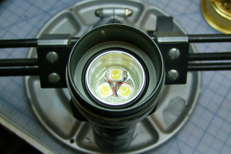
Description - what are these things?
Joule Thief boards ("Battery Vampires") are circuits designed to suck as much energy as possible out of batteries/cells. They are not regulated drivers - they are a boost circuit (create a higher voltage on the output from a low input voltage) and provide current proportional to the input voltage, which is in turn proportional to how much energy is left in a battery/cell. You can make/design your own Joule Thief circuits from discrete components, making your own inductor, etc, so that I am offering here is a small, turn-key board ready to use in your projects (for P60 drop-ins, see more information below).
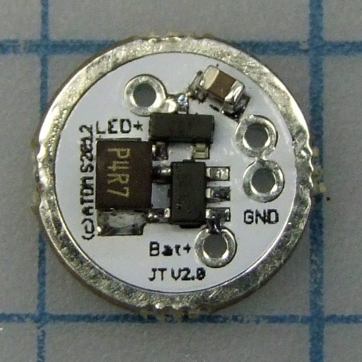
These boards that I designed, built, and assembled are based on the Zetec ZXL383 integrated circuit:
 [/IMG]
Usage/voltage recommendations:
Max voltage for my Joule Thief circuit is about 3.3-3.5 Volts (whatever the vf of the LED is). Anything higher means the circuit is bypassed and you are in direct drive mode and can burn/kill the LED(s). So you can use:
- 1x or 2x new or used, AA alkaline or rechargeable cells
- 1x new or used CR123 cell
How much current can I get?
With the current 4.7uH inductors, with a Vin of 1.5 volts, the output current to a 3W LED was between 50-60mA, and at Vin of 3.0 volts the output current was about 100-120mA (there is variability also due to the wide tolerance with the inductors). Output current varies proportional with the battery voltage, so lowest would be with a depleted AA cell and highest would be with a new CR123 cell, but even there you are looking at only a couple hundred milliamps max anyway - this is LOW power compared to any other LED driver out there as it is meant to really drain cells as low as possible.
How efficient are these?
Like with most boost circuits, the closer the Vin to the vf of the LED, the more efficient the circuit is. However even at lower input voltages, the circuit is still sucking energy from "drained" cells, so the LED will be lit for a long, long time, depending on how much is left in the cell.
The other efficiency number is for the LED. For any given power input to the LED, how many lumens do we get? This is compared in lumens-per-watt, or simply lm/W. There is a very interesting thread in the LED section of CPF's talking about driving the XM-L LED's at very low drive currents, and trying to find the "most" efficient point of operation for an XM-L LED. Interestingly enough, the peak efficiency point for this particular U2 1A bin XM-K was at 150mA, with 163 lm/W, but even at 5mA it was still above 100 lm/W. Given that these Joule Thief boards drive LED's in the 100-120mA range with a Vin of about 3 volts, that makes for a very efficient setup as the LED is making near maximum efficiency..
How big are these?
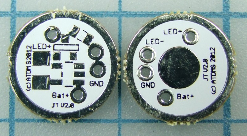
The new V2 boards are slightly larger in diameter than my prototype (V1) boards, but 100% functionally identical. The V2 production boards have a diameter of approx. 0.53" - 0.54" (approx 13.5mm to 13.6mm).
Compared to V1:


Close-up of the new V2 production boards:
Which side goes where?
The new layout has clear silkscreen labels on top and bottom to make wiring easier than before. The metal ring on the outside perimeter of the new V2 boards (on both sides of the board) is tied to ground (GND). GND is also tied electrically to the LED(-). The big metal area on the center of the bottom of the board is tied to the Battery(+), so you can solder a wire coming from the positive side of the battery directly to that large pad, or you can also solder a small spring directly to that center pad.
Like with the proto boards before, V2 boards are all assembled, cleaned, and tested before being shipped out in anti-static material (using anti-static bubble wrap now). However the new boards will not come pre-wired as before as these are much easier to solder due to having the proper solder mask areas and silkscreen labels. HOWEVER, if you ask for them when you place an order, I will include for free the Teflon coated premium wire in your package.
Pricing for V2 production boards:
Price for a fully assembled and tested board is $15/each plus shipping (insurance optional). I bought new anti-static bubble wrap and padded envelopes, so shipping is a tad higher than before. Shipping options:
- Domestic USA first class - up to 5 boards - $4 (insurance is not included)
- Domestic USA priority - up to 5 boards - $7 (insurance is not included)
- International first class - up to 5 boards - $6 (insurance is not included)
- International priority - up to 5 boards - $15 (insurance is not included)
I am no longer soldering wires to each board, but I will be happy to include the premium Teflon coated wire for FREE if you ask for them in your order :D
Payment:
Paypal, cash or credit same price. Paypal address is the same as my gmail address, listed in my signature.
P60 drop-in option:
I have been able to finalize details for the P60 options, and David (nailbender) (I will add the link once I am allowed) has agreed to make the P60 drop-ins based on my Joule Thief boards. So if you want, instead of shipping the boards to you, I can ship to Dave directly, and Dave will ship to you the completed P60 drop-in. Just make sure to note in the Paypal payment that you want me to ship the circuit board to Dave instead.
Here is how the turn-key P60 drop-ins arrangement with Dave works:
- You buy Joule Thief board from me
- I ship board directly to Dave
- Dave makes P60 drop-in to your specifications using my "driver" and the LED/reflector of your choosing.
- You pay Dave directly for his P60 drop-in
- Dave ships directly to you the completed, turn-key P60 drop-in
Dave can of course make several drop-ins for you each with different LED's, reflectors, etc. Dave has some low vf LED's as well, which would be a little bit more efficient as my boost driver would have to work a little bit less hard with a lower vf. Just remember that since Dave is using my "driver", and my driver is by definition a single mode/single level driver, designed to drain AA and CR123 cells down to 0.8 volts, so everything I listed about what the driver can and can't do still applies. Dave is doing the hard work to turn/package the Joule Thief board into a completed module (turn-key) so that it is a lot easier to use ;)
Status - what is available:
I have V2 boards in stock, so I can take orders right away.
PLEASE put your forum user name in your paypal so that I know who sent payment :D
PLEASE put in the Paypal note if you want me to ship the board(s) directly to David (nailbender).
Questions?
Here in this thread, or privately by email (on my signature).
********************************************
2xAA 3mm or 5mm Kit:
The 2xAA kit with either a 3mm or 5mm LED, and all parts necessary (not soldered nor assembled) is $20, and it of course included a Battery Vampire (Joule Thief) board with the appropriate size inductor already soldered.
- Domestic USA first class - up to 2 kits - $5 (insurance is not included)
- Domestic USA priority - up to 2 kits - $6 (insurance is not included)
- International first class - up to 2 kits - $7 (insurance is not included)
- International priority - up to 2kits - $15 (insurance is not included)
If you want me to fully assemble and test the kits, then the following labor charges apply for each kit:
- hand assemble and test 3mm kit = $20
- hand assemble and test 5mm kit = $25 (takes longer to do)
NOTE: I am also offering the Joule Thief circuit board by itself, with the correct 1mH inductor for 3mm/5mm LED's running from 2xAA cells. Price for these boards are the same as regular boards, BUT you need to let me know in your paypal note that you want the "1mH inductor" - if you don't say anything, you will get the default/standard 4uH which will kill the 3mm/5mm LED's.
Questions? Send me email (in my signature).
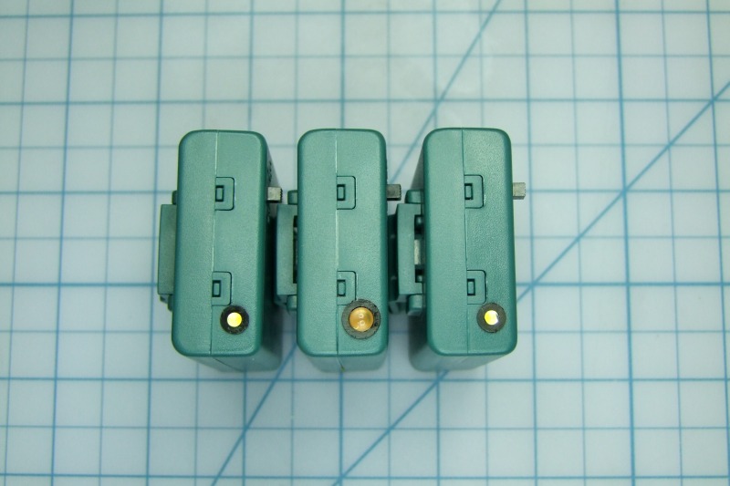
Photo of the completed 3mm AA kit:

Here are 3x completed units: 3mm, 5mm, and 3mm:
I have a step by step tutorial on assembling these, but I will wait until I can post links to share (right now I am too new and I can't post URL's).
Will