crash-testing a MT-G2 on a copper Noctigon, graph done, mod done and repaired :-)

....and it survived :

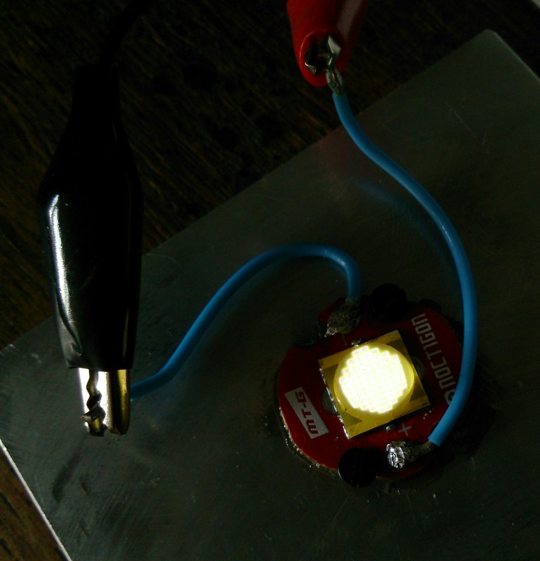
(the MT-G2 after the test, 0.5mA from led-tester)

Ignoring family life once more (girlfriend slowly turning from understanding to quite annoyed) I did some rough testing on a MT-G2 6V 5000K mounted on a Noctigon board and a load of aluminium last night. The test set-up was the same as my more limited MT-G2 test recently, but with a heavier power supply and even heavier leads (16 amp electrical wire for home installation, well soldered to plugs and clamps). The led was so expensive that despite being me I even did the test a bit more thorough than usual, it resulted in even three video's . If they are just too boring to watch (I don't blame anyone who finds watching changing digits for many minutes boring): I will make a nice graph of the data when I have time again to do that, it will take a few days.

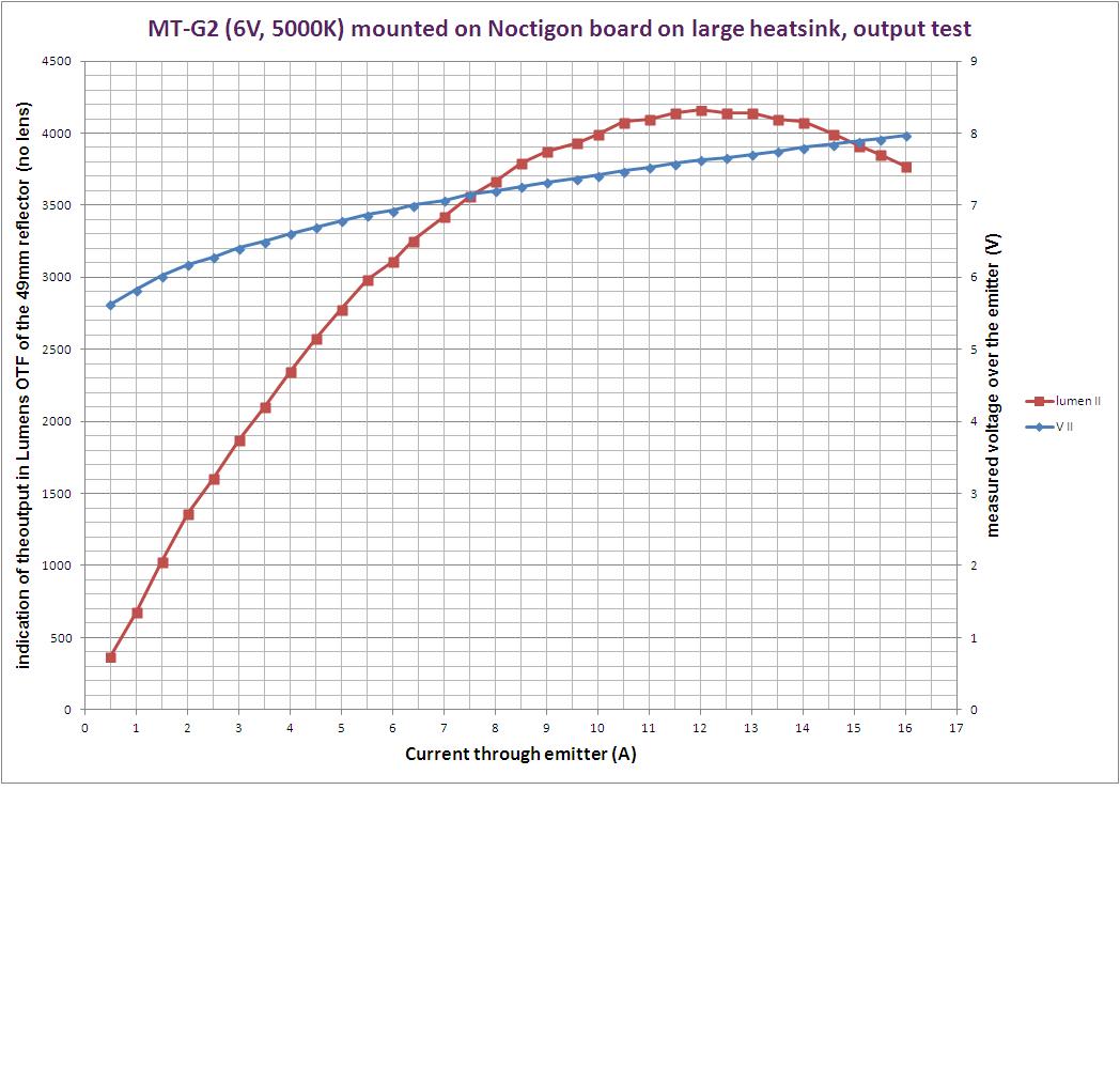
EDIT: I did the graph, it is in post #16

EDIT: I did a direct drive mod too, post #27

In the first video i turned the current up to 7 amps and used my DMM to check the current reading from the power supply. The DMM gave a reading about 5% lower than the current in the display of the power supply.
I find that close enough .

In the second video I used the DMM to measure the voltage directly at the thick and short led wires to get a Vf reading. I trusted the current reading of the power supply. I measured to over 10 amps (you have to look at the video to see how far beyond the 10 amps :evil: ) and found that (you were right comfy !) the output diminishes long before the led blows (in fact I stopped before that). The fairly chunky heatsink eventually even got too hot to touch (120W in the end), so temperature effects may have influenced the results at higher currents. The complete set-up was identical to the XM-L2 test I did a few days ago, so the results are directly comparable. the ceiling bounce lux-readings multiplied by 2.06 give an indication of the number of lumens coming out of the 49mm reflector that was on top of the led (as with the xml2 test, there was no lens on the reflector). One result from the video: going higher than 7 amps does not give significant more output, very close to maximum output is reached at 9 amps. If this experiment with this one led is an indication of how the MT-G2 performs in a flashlight, there is a no need to go higher than that.

After the torture of the second test, I let the set-up cool down to room temperature and did a third run, up to 7 amps to see how much the led had suffered from the high current. I have not looked at the numbers very closely, but it looks like the led survived well, but output has become just a bit lower (don't blame the led for that, after what has been done to it )

So that's it, the led is going to live another life in a future flashlight build. The graph may take some days, when I have the time to make it . EDIT: added graph, in post #16. Thanks for reading

Holy crap! That was brave of you, and thanks so much for this video, I was wondering how much the MTG2 could take.

They are definitely my go-to emitter for a flood blaster now. No need for multi emitter, just drive it like crazy haha. Just need to find a driver which can give that over 10 amps >)

this is cruel! :smiley: but also very interesting, thanks!

Thanks djozz. Terrific effort. If this was running off a nine amp driver, correct me if I’m wrong but the led would only get about 6 amps. If this is the case this driver should be ok. Running 3 26650 batteries and the 5 amp IOS driver the led sees 3.6 amps.

You're welcome.

I'm sorry, I am really not a driver guru, I just happily follow what other people try to drive the MT-G2 (me, I want a good 21mm driver that drives a MT-G2 at 4A and runs on two 18650 -IMR- batteries, have not seen one yet)

Thanks for doing these tests djozz, they are very useful!Keep up the great work! :slight_smile: -Rick

Excellent work, djozz! Thanks for the tests. Now I know how hard to drive my MT-G2 emitters J)

Thanks for coming through for us! You da man! (And I'm sure you girlfriend really was understanding of the need to satisfy flashaholic modsters with test data!)

-Garry

Thank you djozz. Your work is much appreciated. :slight_smile:

Excellent work, djozz! I'm glad the LED survived to live another day. :)

Real nice test! Again, great to know. My girlfriend understands but the wife doesn't...

Nope, not with an actual buck driver (i.e.: not a LD-29 or the like). As long as the input voltage is high enough (with some headroom) above the LED's forward voltage at the desired current, the driver should do the rated current no matter if it's a single 3.3v LED or 3 3.3v in series or a single 6v LED. The buck driver in the S1100 does 3.3A to a single XML and 3.3A to a single MTG2. IOS '5.5-12v 9A' driver does 9A to the MTG2 (I hope it's obvious that I haven't tested that one with a single XML, lol). The IOS '3-18v buck/boost'... see below

Wait, are you asking about that one, or stating what that combo actually does? Is that the '3-18v' one, that claims 5A to a single LED or 3.5A to multiples in series? If it is, the 3.5-3.6A you're seeing is correct... the 6v MTG2 appears to the driver as two 3v LEDs in series. That 5A number is for only a single 3.3v LED. I don't know why that driver does it that way when other non-boost buck-only drivers don't care how many LEDs there are/what the total forward voltage is, but that's what it is advertised to do, looks like it is doing what it says on the tin.

Whoohah… That 2nd video was a bit nerve wracking! :stuck_out_tongue:
I was almost holding my breath for the poor MT-G2… WOW 16A… You sure kept going far beyond the point where max output was reached! J)
Great stuff!
Thanks for torturing testing it. :slight_smile:

Very nice torture :slight_smile:
now, dedome it :bigsmile:

Running the IOS driver you mentioned will run a single XM-L U2 at 5 amps with a couple off 18650.
Running the same driver with an MTG-2 with 2 x 26650 will give you 2.88 amps. Exactly the same setup with three 26650 will give 3.6 amps at the led. Dont ask me why.
I think your measurements for the 9 driver were taken at the tailcap.

Not try to take this thread off topic but to answer questions as they arise here is the results for anyone that has not seen them.

No, my 9A number came from a meter inline with the LED. Same setup did 6.6A at the tailcap with 3x18650 (that's a lot - a lot of current, a lot of abuse for the cells & switch, a lot of wasted heat in the driver, and not a whole lot more light than with a 4A driver).

MTG2 running from only 2 cells is not enough voltage overhead, these drivers really need 3 or more cells in series to work properly with a Vf of 6.3-6.6v (depending on current).

I did the graph, and it comes with the following notes:

-I noted the data of all three runs, and it all appears to reproduce very well. I thought that at least the third run would show some damage (lower output, altered Vf) from the second run mayhem, but looking at the numbers now, that appears not to be the case, the led keeps performing equally well. The graph shows only the data of the second run.

-I can compare the measured Vf up to 3 amps to the official Cree data, and I measure 0.2 V higher, which is significant. For the higher currents there is no available data, also Match did not publish Vf data of the MT-G2. I don't know why the results differ from Cree (is it real, did I measure wrong, is my -not really trash-quality Amprobe- DMM off by 0.2V, is there a big influence from the Noctigon board?). Well, it is what I measure.

-At the end of the test run the though sizable heatsink was just too hot to touch, so temperature may have an influence on the higher current readings (but then, in your flashlight build that will only be worse, so the data just are more to the point as they are now )

Here we go:

no dedoming for me, dthrckt already proved that dedoming can be very unsuccesful. But the way I am going to use this led will make it look like it is dedomed, but does not throw a bit (*mysterious smile*). I'll get back to that when it is finished.

Thanks for the graph djozz. With all this work you have done how and what would you use for maximum realistic performance in a largish flashlight, driver and pill wise?

I am still not very good in driver electronics (only a general idea of what is going on), so no ideas about which one to use, but I do have idea's of how I think the MT-G2 could be driven well.

I will give a general idea of how I ideally use this kind of data to make my idea of a good useful flashlight, and I guess that is not so far from how some others in this forum think. (My game is usually not about setting records while being totally inefficient and burning through batteries in 5 minutes, that's another fun sport).

Using the MT-G2 most factory lights go up to 5 amps, even the ones that use copper boards (Eagletac). That is a good idea, great output and good for efficiency and gives a managable amount of heat. But in this forum we want a bit more and we are not afraid to get our hands warmed up. Maximum output is reached at 11 amps, but the light will be hugely inefficient at that current, a real waste of energy and probably not good for the lifetime of the emitter. My personal rule of thumb with copper mounted leds is to aim at about 3/4 of maximum output: the led is used very well, the visual difference with max is negligable and it almost halves the current neccesary for the maximum output (the performance graphs of all other emitters have a similar profile so this is valid for all emitters). For the MT-G2 on copper and maximum heatsinked 3/4 of max is reached between 6 and 7 amps, so that would be my ideal. In a flashlight build heatsinking will be worse, but I'd still go for the 6/7 amps . The led alone will produce -apart from emitted light- about 30W of heat at that current, so the build needs a good thermal path and sufficient surface area on the outside of the light.

One remark about why it is great to use these copper boards as opposed to traditional boards in flashlights: because the heat can get away from the led so easily, the temperature difference between led and body is less (I believe it is even much less), so the body can be allowed to get hotter while the led is still performing well. This is advantageous in two ways that help each other: 1) obviously you are allowed to make more heat (the led can be driven harder), and 2) the difference between flashlight body temperature and ambient temperature will be larger so a same amount of energy can be dissipated with less body surface. In practice: I have not tested it yet, but my guess is that when a copper board is well mounted with a good heat path to the body, you can continuously keep running a flashlight that is too hot to touch. One design consequence is that the battery compartment will have to be thermally more isolated from the head of the light than usual (i.e. further away).

Sorry, this is a bit of a long answer, and it is perhaps not even an answer to your question .