djozz's test of led4power 17mm PWM-less 5A driver

(this will be a limited post for now because I am going away until next wednesday, I will update this post with graphs and such when I have time again)

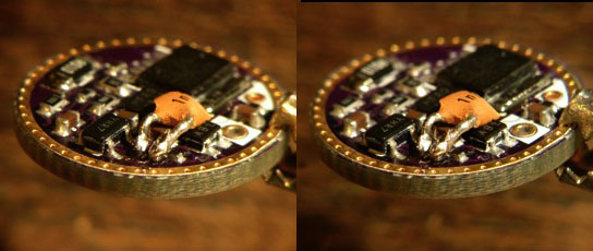
I received led4powers driver in the mail last week and today I had some time for testing. In a PM led4power asked me to change a cap for a different value because preliminary results from HKJ showed oscillations of some kind at certain circumstances. No idea what it was exactly (I know Ohm's law quite well, and not much more than that), but I was to swap the smallest component on the board :sick: . and my local electronics shop did of course not have that small SMD cap so this is the first thing I did to this beautiful driver (in stereo glory):

So far for the nice thin driver :-D . Next I made a cooling mount (copper sock soldered on copper plate) for the driver because it was not supposed to live in air because the overtemperature protection would not work properly then. I soldered the led-wires to the driver and then I soldered the driver on top of the mount:
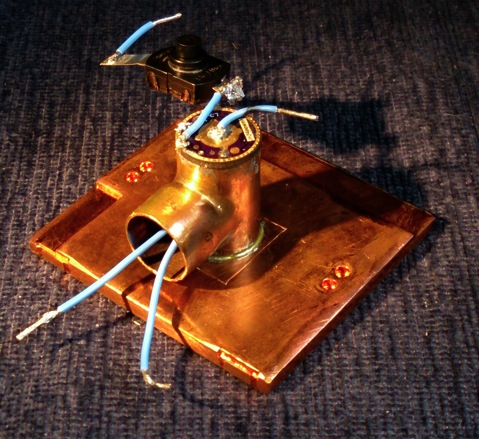
The driver was going to be coupled to my power supply, with a reverse clicky in the circuit. The current entering the driver was measured by the power supply, the driver's entering voltage was measured direct at the driver pads, the driver drove the XM-L2 T6 3C dedomed led from my last test (see for the output of that led my XP-L test thread). The current through the led was measured by a 0.01Ohm sense resistor coupled to a voltmeter, the output of the led was measured in my integrating sphere.

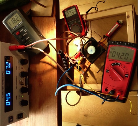
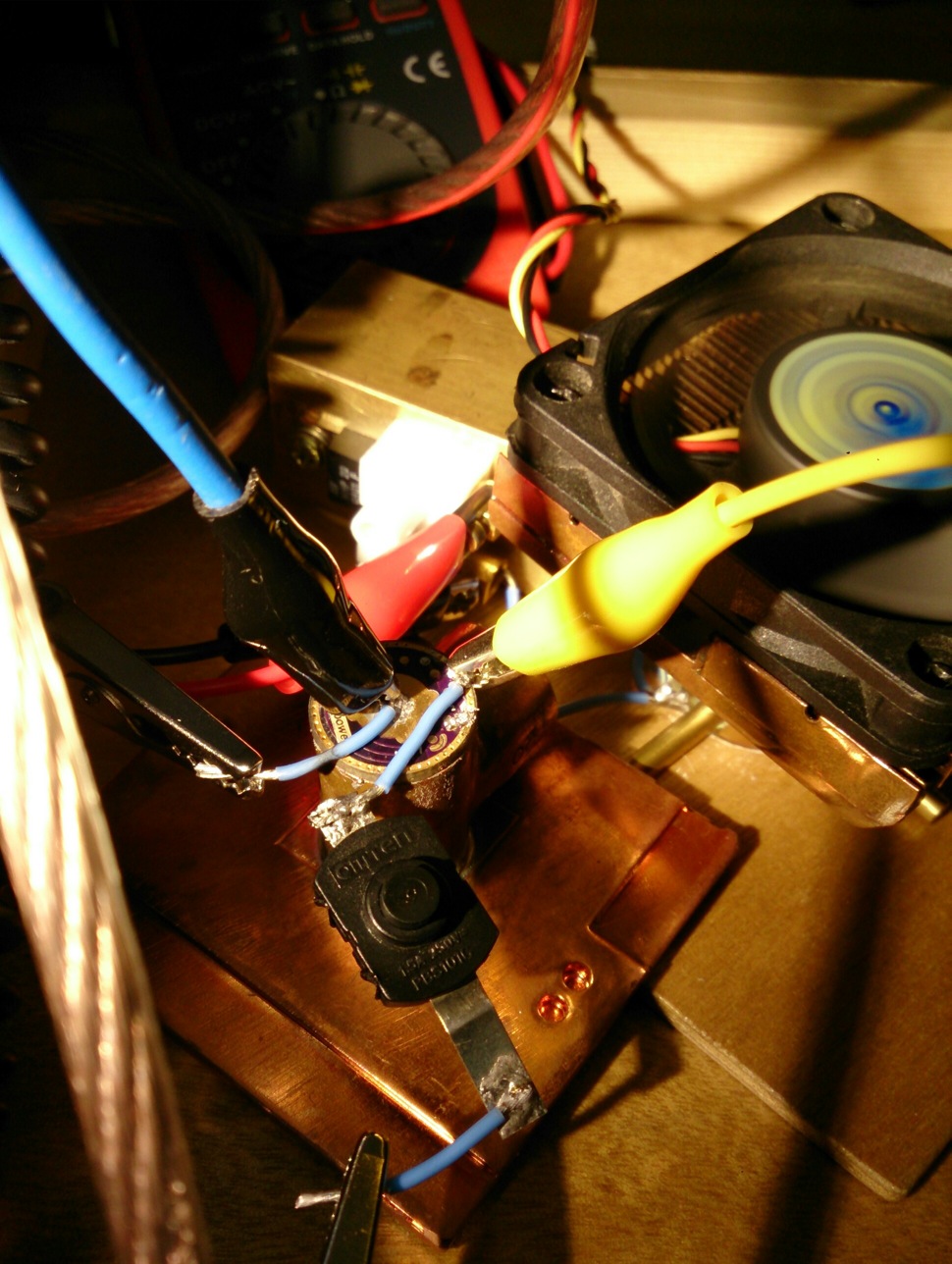
Here's the set-up just before the led mount was put into the sphere (my big DMM is measuring entrance current in this picture, but I needed it for volt measurements so I took it out of the circuit again and relied on the PS current reading with one digit less). The brass block next to the driver mount has the current sense resistor fixed on top.

Here is how it all looks during the testing, with the led sticking into the integrating sphere. You are looking here at the TURBO-test (moon2 engaged) with 4.2V driver entrance voltage (large DMM), 7.2A driver entrance current (on power supply), 7.33A led-current (small DMM, I converted mV to A) and (converted from 1182 luxvalue in photo) 1868 lumen led output (so the led output is exactly as last time I measured it :-) ). Of course no li-ion can keep 4.2V at 7.2A, so this situation is quite theoretical for a flashlight. See the numbers below for lower, more realistic voltages.
I am not so much into user interfaces so I did not test all the features of this driver, I leave that to others. Give me four modes with good spacing and I am a happy camper :-). So the test I did was applying various entrance voltages to the driver (impersonating the various states a single li-ion battery can be in), and see what the driver does to a XM-L2 at the four available modes and on TURBO. Maybe later I will test it on a XP-G2, but that will be a few weeks from now.

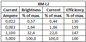
So here I should provide you with all sorts of nice graphs, but that is where I do not have the time for today, so I just present you with the raw data for now and wish you good luck cracking my handwriting and abbreviations :-D . I tested the high setting at many voltages, and the other settings at just a few voltages.
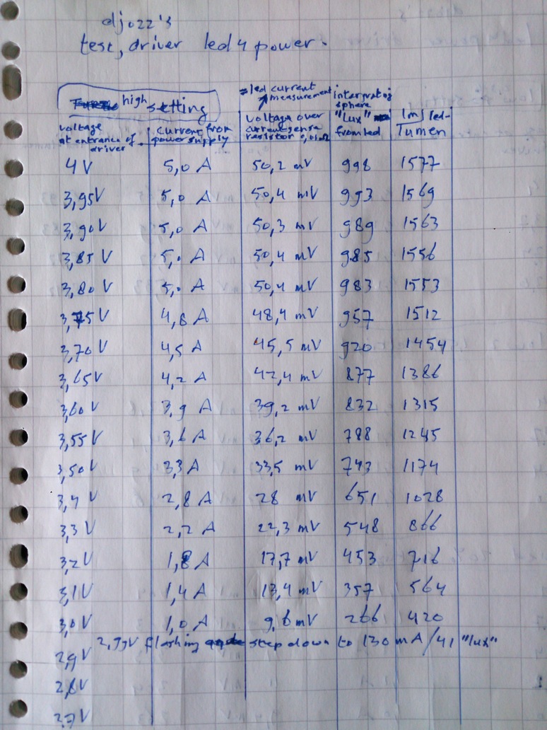
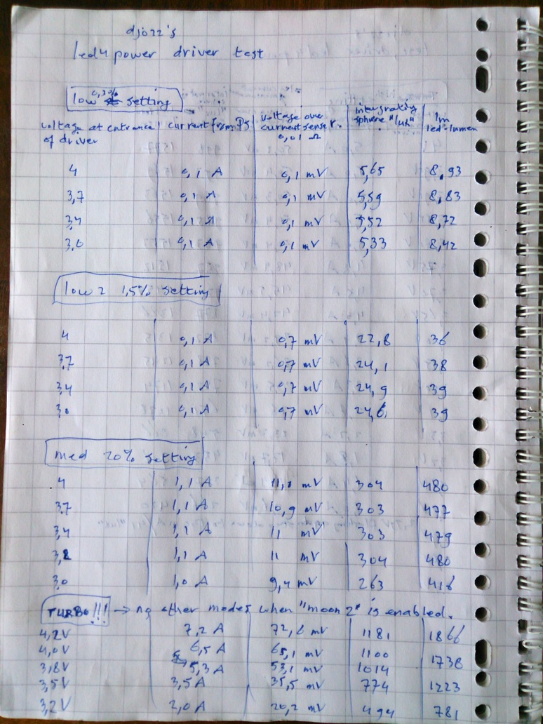
If you have interpreted the data well, you can decipher that this driver does what it promises, I think it is a great driver!

For who needs explanations/graphs/conclusions going with the numbers above, it will not be before next week before I can make and post them :-( (and perhaps even later, I am going camping with the family for two weeks next friday :-) ) .

That's al for now, I hope that you find it a useful test.
Nice tests as usual, that is what I wanted to see.

Dj what cap value do you need?

:-) 1 or 2 nF (I used 1 here), it is the tiniest cap I have ever seen.

Led4power published some very good efficiency numbers for this driver. I’m hoping to get independent confirmation and comparison between this driver and an equivalent 5A pwm driver in a lower mode. It was suggested that actual lumen output in a lower mode would make a more accurate “apples to apples” basis for comparison.

me, reading those tiny words:

thank for doing those tests.

I wonder when RMM will start to carry these…

This test is not very good for measurements at the lower currents because both the powersupply current reading and the senseresistorvoltagereading are not sensitive enough for that. So that interesting efficiency at low current I can not measure well. I need my new extra DMM (in the mail somewhere) and then I can do that a bit better.

Anything significantly less than full power would do, say 1A. Just enough to see the difference in efficiency between them.

Couldn't you just compare a Nanjg driver with 3 350 7135's (1.050A) with a Nanjg having 14 350 7135's (4.9A) with a 21.4% PWM mode? Amps are theoretically the same, but one uses PWM's based on 4.9A full power. Compare lumens output.

Sure but the idea is to verify led4powers driver not a 1A nanjg.

It should be the same,since 7135=constant current.

Wednesday would be the first option to do something like that but I'm not sure I will get to that. I could hook up a 105C with some extra chips and see what it does at the lower modes.

A quick calculation from the above numbers (let's take the most optimistic situation :-) ): on medium setting, at 3.2 V at the driver entrance, the entrance current is 1.1A and the output is 480lm. That is an efficiency of 480/1.1*3.2=136lm/W, if the led wasn't dedomed that would have been ~150lm/W, pretty good for a T6, and not much loss in the driver here (on med setting, higher voltages than 3.2V appear to be burnt off in this driver). In a flashlight there will be loads of extra losses of course from battery contacts-springs-switch-reflector-lens.

You verify things to make sure they are what they should be. I have little doubt that the results will be favorable but until it’s verified it’s just a claim.

Thing is with this driver:

I am sure the lower modes are current regulated, not with pwm. Then if I know what currents we get (as measured above), and see that the current before and after the driver is the same (as shown above), same as a lineair driver, I see that the only thing it does different from a common lineair driver is that the lower modes really have lower currents, not the highest current cycled on-off. Now for myself, knowing the current/output current curve of any led, I do not need any measurement anymore to know that the efficiency at the lower modes of this driver is noticably better. The improvement can directly be derived from the led's current/output curve, no measuring needed.

Thanks djozz again for your testing. I'm not sure that you should go away as I need my daily dose of djozz. This will be harder on me than giving up the fags and the grog. Please dont go.

If you do decide to go enjoy your time away. I know you will miss us just as much.

I believe I already proved something equivalent by using a higher resistance setup with the LD-1 and seeing only the high mode suffered in loss of amps, not the lower modes, but I should prove that in a PWM driver, all modes are scaled down proportionally. I agree certainly with the direction Scott is taking, that we need independent confirmation, but then again there's no point in taking it to the nth degree.

I think we agree to all the benefits this type of driver offers:

  • much better efficiency/output for low/medium modes (I agree we need to confirm it)
  • a standard high mode of 5A with no games to get there
  • a "turbo" mode that is a true DD
  • also love the fact of a clean spring side and low profile component side

There's not much flexibility in the mode configurations right now, specially for standard power switch lights, but hoping this can evolve. I'm not sure right now what can be proposed to address this, but I certainly see a need for a 3A or 4A as a high in a set of modes for example, and the beauty of this design is no hardware change for doing things like this.

HJK's test(related to low modes efficiency):

"One of the nice features about a linear driver without pwm is the better efficiency of the led. Here I have tried to measure it with a lux meter. First I measured lux at 5A and defined that as 100%, after that I measure lux at the lower settings. With pwm the efficiency of the led would have been exactly the same, because the current is the same, but only applied part of the time. With this driver the current is reduced and the efficiency goes up. At 1A the brightness is supposed to be 20%, the lux is 30% of max, i.e. about 50% more brightness that a pwm driver would have given."

@Tom E

I agree with all your opinions.If you want 3 or 4Amps as a max. you could just change sensing resistor,it's that easy(other modes are reduced by same factor also).

:-) thanks, highly appreciated. Same with me, I need my regular MRsDNF flashlight build thread read, starting with huge bars of aluminium secretly bought from the wife's money, made into flashlights with the best looking tailcaps in the world :-)

I'm sure I will keep track of BLF during the holidays, but I will miss the hands-on part of the hobby :-(

Thanks guys, I’m not trying to be picky or doubtful of Led4power it’s just that any validation process requires independent reproduction of advertised characteristics. It seems HKJ has done this already so I won’t keep harping on it. 0:)

@Led4power
Will you be offering them at different max drive or releasing the Rsense formula? This driver sets a new standard for single cell drivers. Given the popularity of the Oshpark 10-15mm linear drivers a complimentary version using the lfpak33 at 2A max would probably do well also.

0.010 ohm is stock (5A)

If you want for ex. 2A max.,calculation is: Rshunt=(stock current/desired current)*stock shunt=(5A/2A)*0.01=0.025 ohm

Use quality metal alloy sense resistors,normal 1206 resistors have too low max. dissipation rating,and high temperature dependence(ppm/C).

Maybe I can reduce its size to 15mm,but I don't think 10mm is possible.If there's enough interest,maybe...