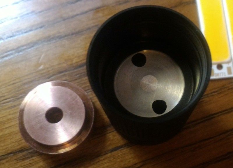
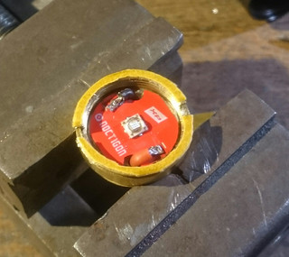
I opened my brand new B158B, and make it a DD single mode (no driver).
It sure kicks some kCds with a 30Q !
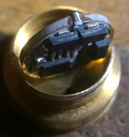
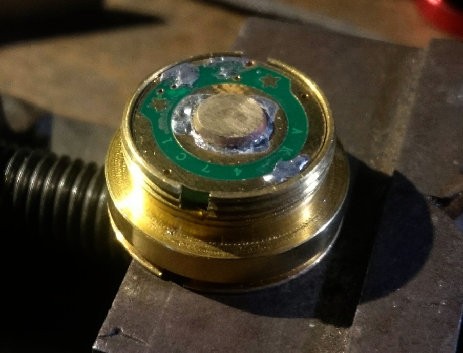
Those new pills are really cool to mod, you have a contact plate and then a standard 105C driver (8*7135) floating inside ![]()
I opened my brand new B158B, and make it a DD single mode (no driver).
It sure kicks some kCds with a 30Q !
Those new pills are really cool to mod, you have a contact plate and then a standard 105C driver (8*7135) floating inside ![]()
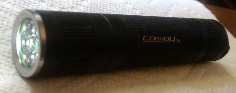
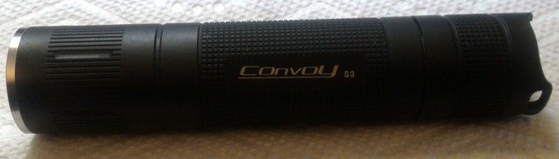
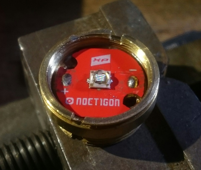
Just finished a Convoy S3 triple
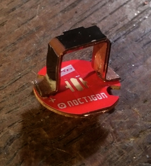
Spacer from kiriba, XP-G2 R5 4C from Simon @ $1.50ea on a Noctigon. NUV Fet+1 Bistro from MtnE.
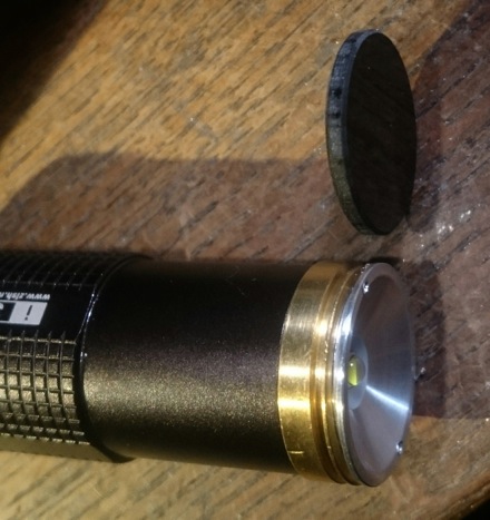
Soldered this Noctigon myself, yay… Soldered the MCPCB to spacer and spacer thermal epoxied into host. Bypassed SW spring.
Lapped the spacer into head to assure as much contact as possible.
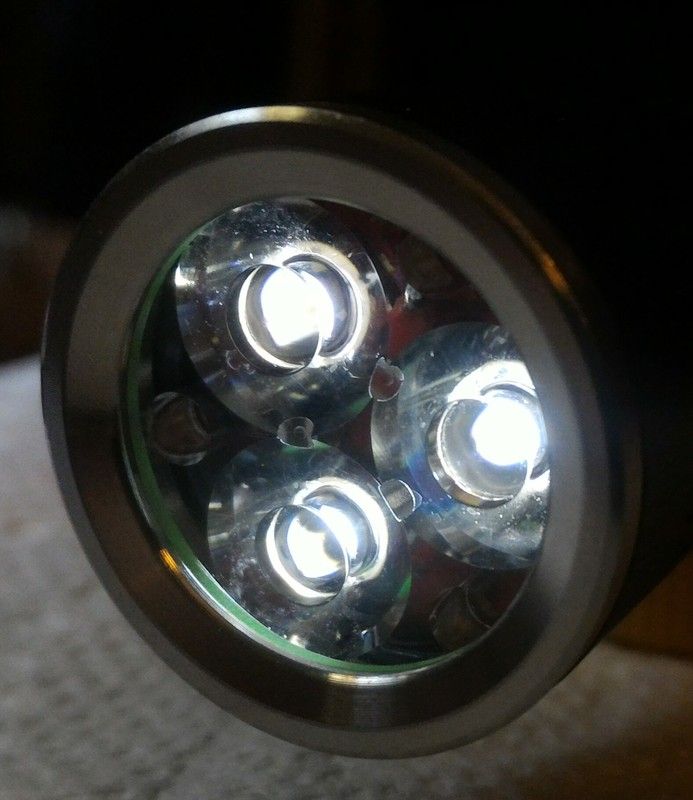
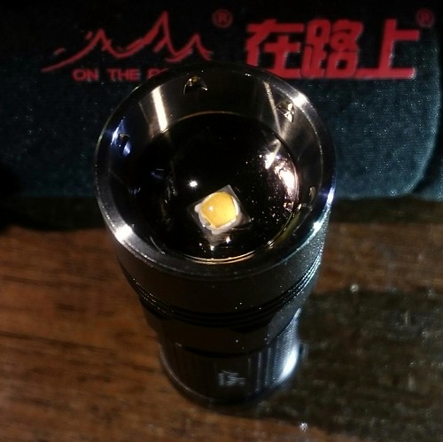
One emitter slightly off color in ML.
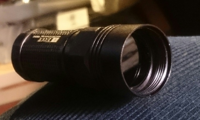
Although not an in depth mod really , I thought I would post this since the Thorfire VG10 seems to be a hot item in another thread right now on sale through Amazon.
Also this IS the older version of the VG10 with the press fit driver in it and NOT the one with the screw out retaining ring like the newer model has.
All that was done to this light was a simple MCPCB swap using a Noctigon board with XM-L2 U4 1A dedomed emitter on it and a spring bypass. It did make a big difference in the throw and the tint of the light in the end though.
Original at 95 yards from gate

Mod at 95 yards from gate

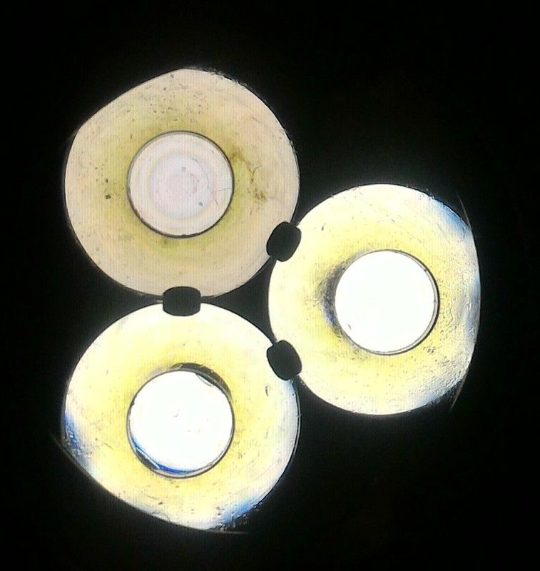
Seems that the emitters are not ok. Two are blueisch and perhaps a little dedomed, similar to the Astrolux S41S with the first glued head (e.g. ENEDED - #376 by Bruno28). The third is too dim.
I am More than familiar with S41 issues. These were 1.50ea so I am not at all woried. Run it till it dies completely. I’m not good at reflowing yet.
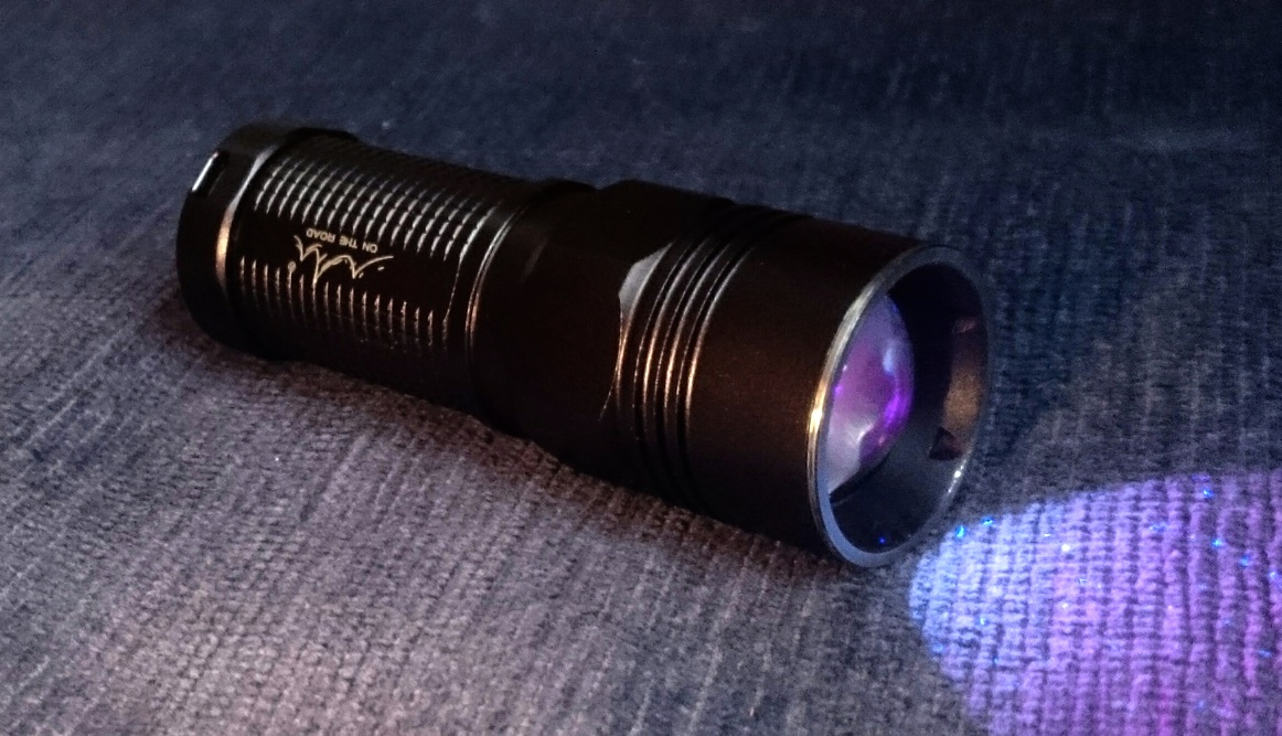
Since I gave away my On The road i3 (modded with BLF-A6 driver and XP-G3 4000K 90CRI) recently, which was my favourite EDC, I had to rebuild it. I had two spare On-The-Road I3 zoomies waiting for modding, and yesterday I re-made my EDC, with the BLF-A6 driver again but now with the Nichia 219C 3500K 92CRI. It is even nicer than the XP-G3 one for three reasons:
1) the tint is even better,
2) the die of the 219C looks way less ugly than the XP-G3 (but still ugly enough to add a 1.5mm thick brass ring behind the pill to stop the slider just before sharp focus of the die),
3) that brass ring causes the pill to be a bit further out, allowing the slider to get closer to the led in flood position causing an even wider spill than the stock i3 :-)
I made no pictures of the mod, apart from this one:
________________________________________________________
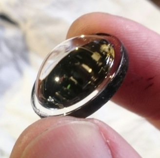
Today I modded the second i3, and made pictures of the mod this time. Since the i3 came out I wanted to mod it with a 365nm led, because it is the only small zoomie with a glass lens (polycarbonate optics do not transmit 365nm, PMMA a bit better so they claim, but have not tried that). The stock i3 has a somewhat silly reflector-ish ring screwed in the pill that you want to get rid of anyway (not good for a nice beam), and without it there was just room for even a 2mm thick ZWB2 filter on top of the (21mm diameter) pill:
The led will be a LiteOn 3535-size 365nm led, which is about the brightest 365nm led around in that footprint, but it needs the ZWB2 filter because it emits quite some greenish light as byproduct. Unfortunately the tickness of a Noctigon combined this led sticks out of the pill, in the way of the filter, so as so often before I had to sand down a Noctigon to 1mm. I soldered a copper handle on the board so that I could use the disc sander (and lots of water to cool the board every few seconds).
The led had to be reflowed on the board, and the board soldered to the brass pill (because there will be no disc anymore to screw down the board).
At this point I noticed that the latest few LiteOn 365nm leds that I ordered have a different die than before. I tested this led with the old die very well and I'm not sure how this one will perform. The plan was a AK-47 C1 driver, for 1050mA, and I hope that is also a sweetspot for this new led ![]()
The stock i3 has a brass ring to put the driver in, that can be press-fit into the pill, but that ring allows only a 15mm driver. Without the ring the driver can be 16mm which is easily made by sanding down a 17mm driver a bit. I hate soldering drivers to pills though, so I created a bulge for the driver to become press-fit and make negative electric contact at the same time. The bulge is a piece of wire (actually a lead from a common resistor) bended in a circle through a via and outside around the board, then soldered in and filed to shape.
And here is the driver in place. I soldered a thin brass disc on the batt+ pad to be able to use my flat top Efest 16340 cells. The second star was connected to ground for low-med-high, no memory.
To attach the ZWB2 filter to the top of the pill, I used some (ancient) double-sided tape:
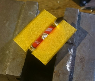
I left the top cover of the tape in place because the pill first had to be screwed into the body, with the filter in place at this point, I would not have any grip on the pill to do that. After screwing the pill in place I could stick the ZWB2 filter on the pill. In the event that it gets loose there is no real problem, the filter can not go anywhere and will float between led and lens without loosing function (but I don't like the idea of it rattling, the sticky layer on top of the pill will at least prevent that)
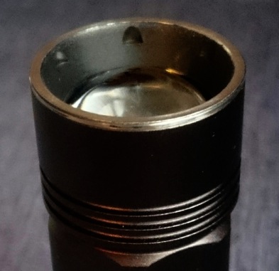
Here's the light without the lens but with the filter attached to the pill:
The lens was sanded rough on the edge and blackened with a black permanent marker, it helps eliminating an ugly and wide ring in the beam of the i3, and you certainly do not want that ring in 365nm because of safety reasons (btw, this light will be far from safe anyway for non-educated folks who happen to grab it to see what it does, no light to be seen and still retina damage).
The bezel was blackened on the inside with some heater paint to prevent possible reflections og UV-light to the side, it does not stick very well on stainless steel, so it will wear off eventually.
There you go:
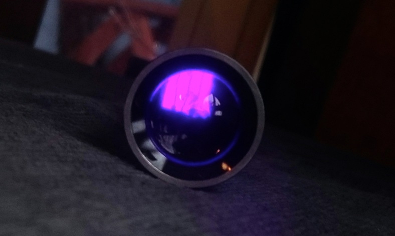
The camera picks up the 365nm a bit, with your eyes you will hardly see the led, if you are stupid enough to look into the flashlight this way.
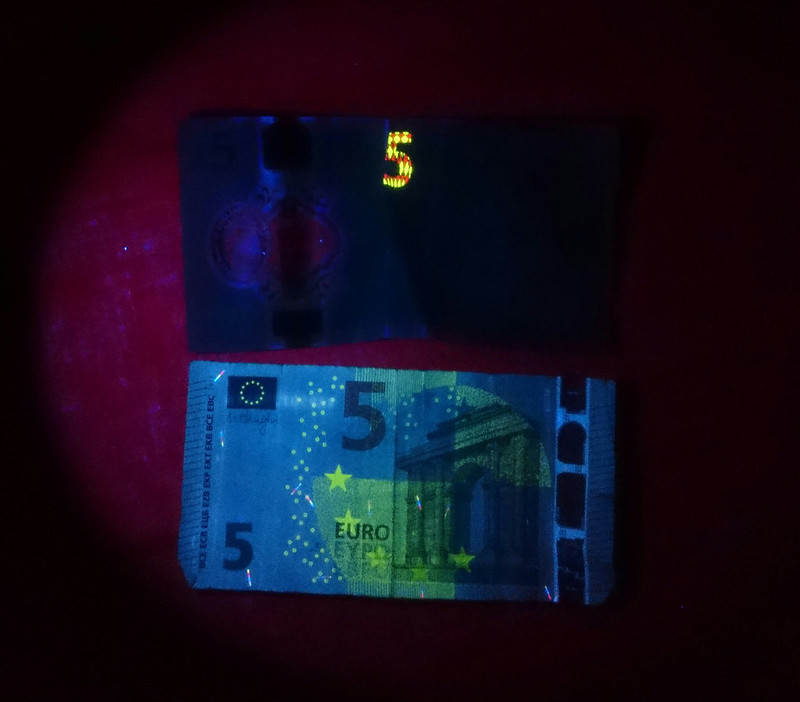
So does it work? Oh yes it does. The output is comparable to a 1050mA S2+ shorty-mod that I did with this same led (but old die), so the new die seems to work well enough. The spot is a bit brighter (and tighter) than the S2+ spot, and the flood is very even which can be useful too. All in all, I think this light is about as functional as my S2+ shorty-UV, but it is smaller and has a higher cool-factor because it is a zoomie! ![]()
Great job!
I think I should try reflowing new emitter with some method, my TIP is CW-tinted which means it is pretty nasty green ![]()
Nice UV zoomie djozz :+1:
Thanks! I modded my hobby-corner of the livingroom into this mess today:

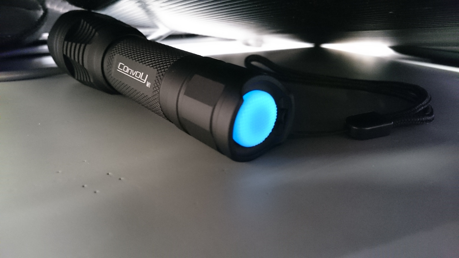
I made a few things on my new Convoy M1.
It arrived with the new design driver but with green color and old firmware.

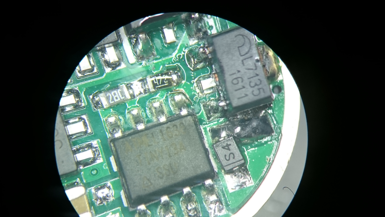
I added two extra 7135 to the driver:
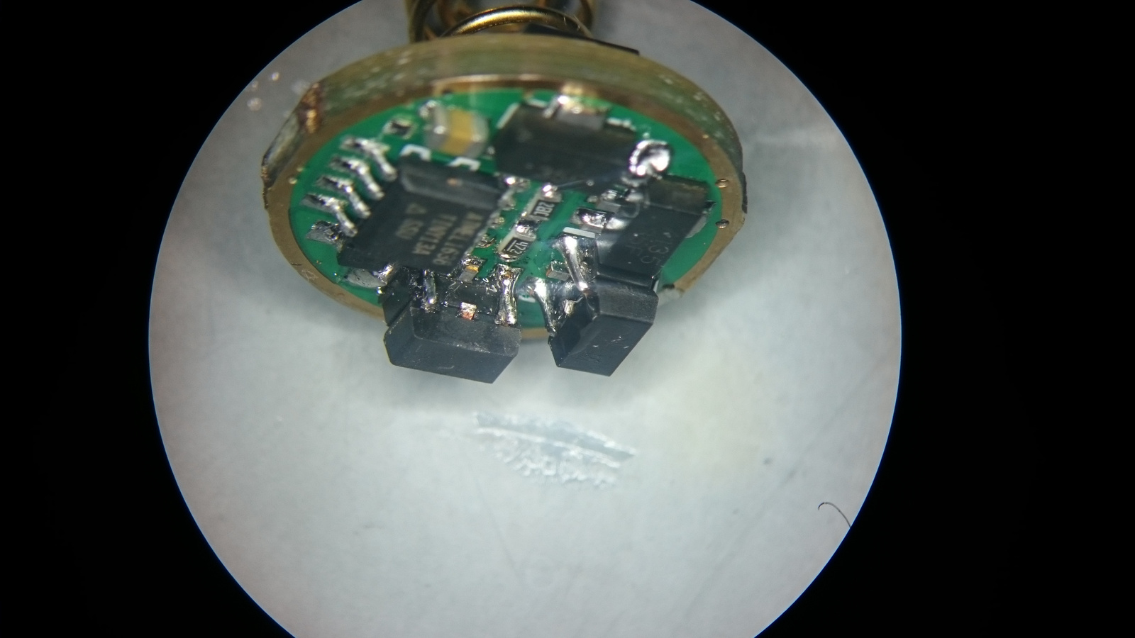
I wanted to flash the new biscotti fw but for this new driver I needed to cut the trace from MCU pin5 to GND (over the top right leg of Atmel) and then the biscotti programmed succesfully:
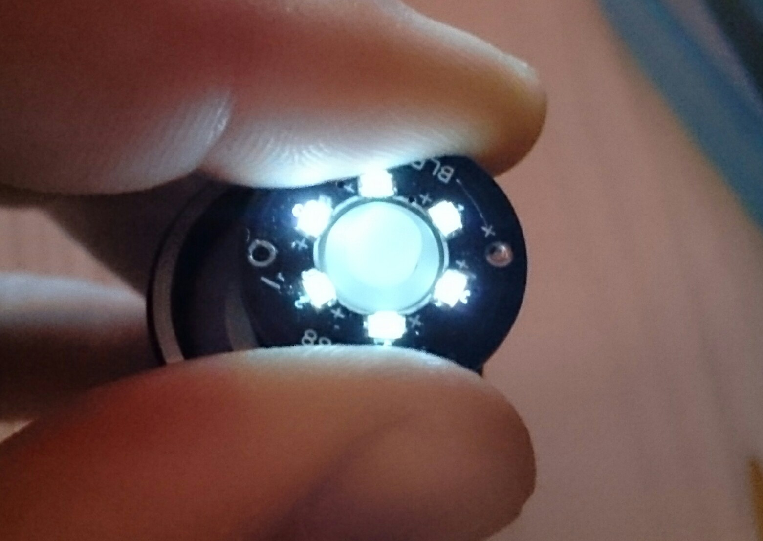
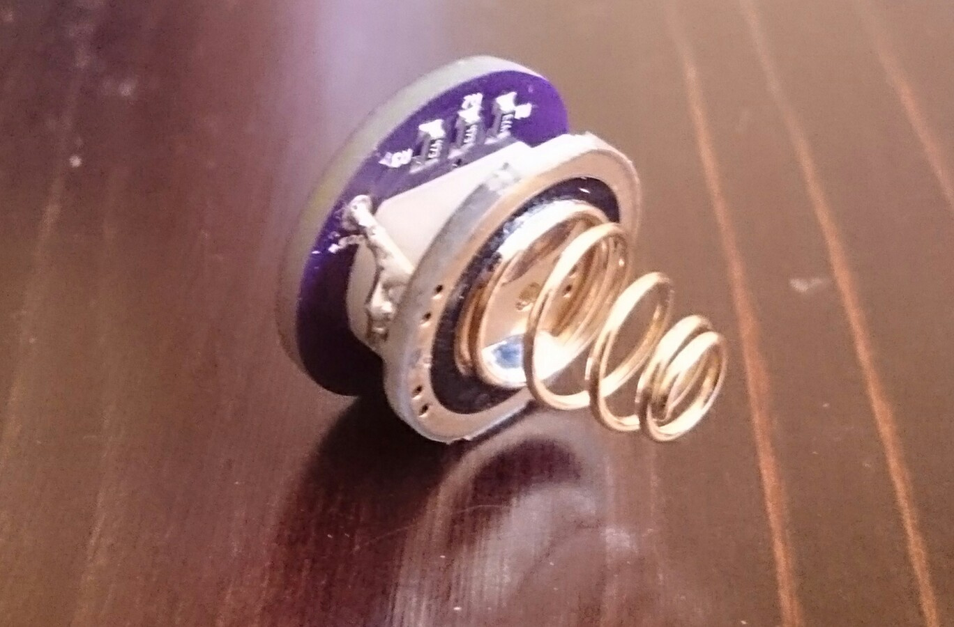
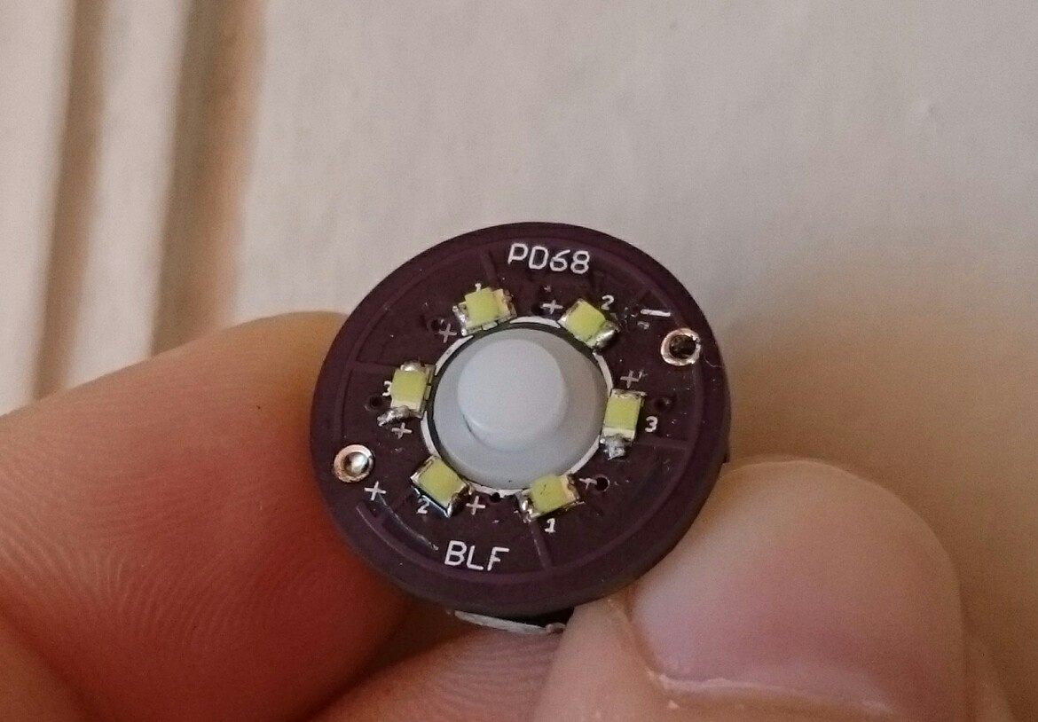
And changed the switch boot to blue from Simon’s shop and added PD68’s lighted tailcap ring board in it with white LEDs and 47K resistors for each two leds:
It was a bit tricky to place the bleeder resistor on driver but next to the battery spring I solved it with a little wire piece and an 1K resistor. The tailcap light draws 0,088mA ![]()

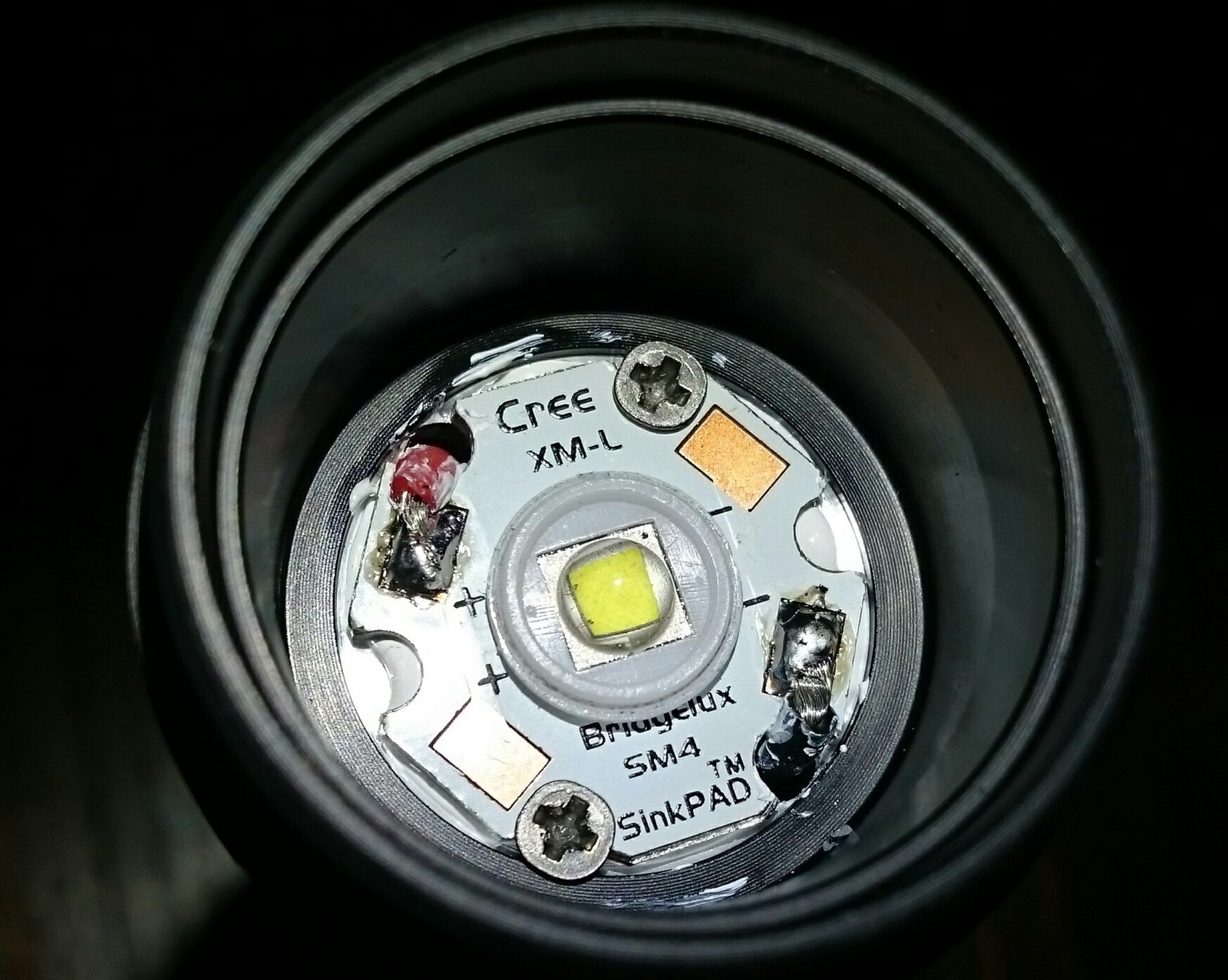
And reflowed the LED to a sinkpad because cooler is better!
EDIT: some more pics:
Nice mod, Zozz! Good idea for the tail lighting with blue cap and white leds, I may copy that ![]()
Thank you! I added some more pics ![]()
I put 3 219c R90 SW403 emitters with a MtnElectronics FET+1 Bistro driver in a Sinner Copper Tri-EDC. Finished it off with a lighted orange tailcap:


Nice :+1:
0.000088 amps??
How do you even measure something that small? What multimeter or clamp meter do you use?
I put a bleeder on a 105D driver which is a similar layout to the new Convoy drivers (7135’s positioned at 3, 6, 9, and 12 o’clock). I used the same method - a jumper wire. Good to know it’s not a crazy idea (or at least I’m not alone in doing so)
From the specs it doesn’t seem like it can measure that low accurately…?
Are you sure it isn’t 0.088 A instead of 0.088mA?
It’s in the specs:
ADC:
Range: 0 mA-10A
Resolution: 0.1 µA-10 mA
and 0.088mA is 88µA


