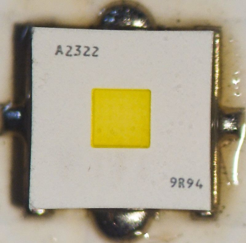
Reflow conditions tested of Osram KW CSLNM1-KW (White Flat 1mm2)

There was some discussion between me and led4power in the White Flat thread about my 1mm2 White Flat test. He found in his test a maximum at 1A higher than me, 5.5A while I found 4.5A. That started me and him questioning my method (I always do that anyway) and that resulted in led4power offering me a bunch of White Flat leds plus 20mm 3030 DTP boards for them, so I could test our different ways of reflowing to see if the difference could be found there. Thanks a lot l4p for providing this substantial amount of parts at no cost for this test :+1:

The set-up, as suggested by led4power:

*3 leds came already reflowed on the 20mm boards by him, done with proper method and equipment and his leadfree solder (SAC305)

*3 leds were reflowed by me with led4power’s SAC305 solder paste (he sent a blob of it in the package), in my usual way: ample solder paste applied by hand, controlled reflow on my heat block at 220 degreesC. For DIY a thoughtful method, but hardly the perfect recommended conditions.

*3 leds were reflowed by my with my own cheap chinese 63/37 leaded solder paste, in my usual way.

So this is an investigation of how our results became different, but at the same time this test gives some general insight in what the influence of different ways and accuracy of reflowing leds is on performance. The White Flat with its high power and very small solder pads is the ultimate subject for testing that.

Earlier, 5 years ago, I found while testing a XM-L2 on 6 widely different XM-boards up to 7 amps, that the DTP vs non-DTP boards made a difference, but once you are DTP, the performance is close, even the thickness of the solder layer hardly mattered. 6x 20mm XML-ledboard comparison . But the XM-L2 has large pads…

And of course this is an opportunity to see performance variation over 9 leds from the same reel, although only per batch of 3 independent of the other variables tested.

As these 9 led tests were about to generate a torrent of numbers, all to be written down and typed in by hand by me (I’m going to develop computer skills when I retire in 14 years :slight_smile: ), I limited the current readings to whole amps, starting at 1A, increasing by 1A each time at precisely a minute, up to 9A. This makes the spacing in the graph a bit rough but it does not affect accuracy or make the results less comparable.

Led4power even suggested a preferrable order in which the leds should be tested, so that possible effects of the order on the results were evened out (I do not see order effects btw). And so I did, the leds were tested in the following order:

djozz Pb #1
djozz Pbfree #1
l4p Pbfree #1
l4p Pbfree #2
djozz Pbfree #2
djozz Pb #2
djozz Pbfree #3
l4p Pbfree #3
djozz Pb #3

Testing was done following my usual method testing voltage and output with cooled solid copper mount and my integrating sphere. I did not graph all the voltage results because they were close to identical for all 9 leds and I did not see any relevant data in those numbers. The test results:

My first observation when looking at the data is that the performance of all 9 leds is reasonably close: in the region that most flashlight builds are expected, close to 5A, the output variation in these tests is about 6%. Without measuring you are not going to see that output difference in reality in your flashlight build.

So the first and most important conclusion in my opinion must be that it does not really matter which led you pick, or what solder paste you use, or if your reflow technique is careful DIY or professional: the performance of the White Flat will be similar.

The second observation is that my first test of the 1mm2 White Flat a few months ago showed indeed a clearly worse shedding of heat compared to these 9 tests. These new tests are very comparable to what led4power found at the time. That is the good part, my general output test setup matches l4p’s setup reasonably well after all (at these power levels at least). The bad part is that I was wrong and he was right about my first test, maybe my reflow was bad, or it did matter that the led was reflowed on an ill-fitting 3535 board.

If you go into detail looking at the graph, you may see that apart from led-to-led variations, the tendency seems that led4power’s reflows with same leadfree solder paste gives a bit better performance than my reflows. But also that leaded solder performs a bit better than leadfree. But this may all be pretty insignificant given that it is all too close to the variation that is already present among the 9 different leds.

All that testing was tedious, but I think the results are pretty insightful. I hope that this adds a bit to the general BLF knowledge!

Excellent systematic work djozz. And great information for all modders. I hope everyone doing their own reflowing sees this.

Thanks Scientist.

I forgot a pic, 1mm2 Flat White at 9A :smiling_imp: in the test-mount pointing down into my sphere.

Thanks djozz!
I wonder what’s the cause for leaded to perform better…IIRC it has worse thermal conductivity so it should perform worse.

I have some hypotheses.

  1. Worse wetting properties of leaded solder caused some voiding
  2. Higher reflow temperature hurt the LEDs
  3. For some reason thicker bond line??

The hypothesis 2 can be tested. Could you please zoom in the 1A part of the chart? If LEDs are fine there should be no difference in their performance.

Actually it could be useful to use 1A results as a correction factor.
Scale all the curves so they start with the same value at 1A (let’s call this value “100%”). This way we could separate thermal properties from LED efficiency variation.
Note that this works only as long as efficiency variation is significantly larget than test variation.

I do not think that zooming in on these data will tell anything extra, the method may be too coarse and the led-to-led variation too large. Think digital zoom on your camera.

And even if you could, what would that sub-percent extra knowledge signify in how you build your flashlight?

Your previous point of view was an assumption based on a sample of one (1).

To me this is really a test and a win-win situation for all of us. Bigger sample and comparable results.
Thanks djozz for testing and proving. Thanks to led4power for supplying the guinea pigs.

I assume that if your method has N% accuracy at high levels, it has close to N% accuracy at low levels. But the display accuracy is not the same. At top levels, the size of a symbol is equivalent to about 1.7% of output. At low levels it’s 3 times as large. Similarly line thickness relative to output triples as well.

It’s artifact of how you chart. By “zooming in” I meant “draw a rescaled subset of this chart”. This would get rid of the mentioned charting artifact, enabling the readers to tell the points apart.

And why does it matter to me?
Your chart has shown some differences. These hint at the reflow process having an impact on performance. Optimizing reflow could make our lights brighter.

The first step to otimize is finding a space that can be optimized. You and Clemence have shown it.
The second step is understanding what’s going on. And that’s why I ask for the zoom, hoping to extract some insights from it.

There you go :slight_smile: , mind that the axes do not cross at zero.

Thank you djozz. :slight_smile:
Very close together. So the principal difference in performance is heat handling. I verified my memory - yes, SAC305 should have better thermal conductivity than SnPb. The results seem to show the opposite to be true for these 9 bonds…

Though the djozz SAC305 samples actually seem slightly lower then the rest even at low current (at 2A - all of them, at 1A it’s unclear, 1 or 2). This may be a small sign of overheating but with a difference so small it may be a testing variance just as well.

Nice work :+1:

Thanks djozz and led4power.

A single test of a single LED isn’t very conclusive, but of course it is better than no test data, and it does represent a possible outcome even if it happens to be an outlier.

Thanks for testing Jos!

Judging from the picture above, I would say LED central pad solder layer thickness of djozz Sn samples is visibly greater than djozz Pb, you can tell that by amount of excess solder on central pad "fins" displaced by LED.

All 3 djozz Pb boards look like they have near optimal amount of solder on central pad - there is very little excess solder on visible parts of central pad, on the other hand djozz Sn boards look like they have too much solder on central pad (obviously spherical surface of solder excess).

And because solder thickness of djozz Pb vs Sn is not equal (highly likely), it's hard to judge performance Pb vs Sn. Difference in thermal conductivity (~15-20%) is potentially much lower than difference in solder thickness, which could easily be greater than 100%.

But if we compare l4p Sn vs djozz Sn, there is obvious difference in output, l4p performs a little bit better, not much but there is enough to see it.

If we take l4p Sn as reference with near optimal solder amount/thickness, difference can be explained by thicker layer of solder on djozz Sn samples.

So in my opinion, this test shows that thickness of solder layer underneath the LED has visible impact.

There is one unclear thing - initial djozz' test which showed quite a bit lower performance/max. current that this test, but if you now look at soldering job of initial test:

you can clearly see there is more Pb solder underneath that LED compared to djozz test #2 (this thread).

Only other explanation could be non-fitting 3535 DTP PCB which maybe increases thickness of solder layer.

To me things look more clear now - thick solder worsens performance, Pb has worse performance if we compare "thick Pb solder djozz test #1" VS "thick Sn solder djozz test #2".

Oslons on 3535 board almost never allow squeezing excess solder out during reflow. During reflow I always tap the led down with tweezers on opposite corners to let the led sit as low as possible, usually the led sucks itself down to the board and eventual excess solder balls resulting from that can be wiped away later. That works well for the fitting 3030 boards, but not for 3030 leds on 3535 boards. Instead for Oslons on 3535 boards I try to optimise the amount of solder beforehand, I did that for the first White Flat test too, but that is not 100 accurate, the led will likely not sit as flat on the board as with the “squeeze-out” method.

So the influence of a thicker solder layer on the performance in the first test could be there indeed. I’m not so sure about varying solder layer thickness in the 9 led-tests of this thread having so much influence on performance that you can distinguish that from led-to-led variation , all leds sat really flat on their boards as far as I can tell.

But at least we are looking at limited differences anyway, there’s even with this quite extreme high power/small solderpads White Flat led not a huge performance gain to be had by going for a perfect reflow. Maybe measurable (which is important enough for many :slight_smile: ) but nothing disastrous.

Thnx for this test Djozz and l4p for providing. Verry good information.

It makes me more confident about my own led reflows and the 63/37 paste that I use.

Will try to keep the amount as less as possible.

Likely, too little solder is worse for the performance than too much :stuck_out_tongue: .

Good point on the picture analysis L4P!
But then - your reflows actually squeeze the least amount of solder. This doesn’t seem to explain the djozz SnPb win. Your joints show lower excess while using more conductive solder.

Ok… I will change nothing :wink:

It was demonstrated elsewhere (by Clemence iirc) that the higher reflow temperature required by lead free solder can affect LED output by a non trivial amount, iirc up to 10%. In other words, reflow temps damage LEDs. (probably some more than others) This is another factor that should be considered.

I do not think Clemence has demonstrated that, at least publicly.
It was in some Nichia papers but very unclear how does it affect us.

Clemence has demonstrated improved performance of Nichia E21A with pure Indium solder. It’s still unclear how does it translate to other emitters.

That's because there is right amount of solder so there is very little excess solder left, just enough to cover gold plating. Osram domeless 3030 LEDs like white flat are super lightweight and they rather float on solder than squeeze it to the sides. So you can easily put too much solder, bigger and domed LEDs have higher mass and they can push some of excess solder.

I agree with djozz, this test is not over - resolution and measurement accuracy is still to low for definite conclusions.