Multi talented guy here fellas. Someone into black magic and can speak fluently in, not sure which, either Chinese or Swahili.
We are lucky to have you around gchart. love your work. ![]()
wait, you will use 3d printed parts in final product?? i just noticed that, actually it was your build that inspired me to enter with a 3d printed light. just like your holders inspired me to learn graphic design. looking forward to see finished build,
Nope, no 3D printed parts in the build. That was merely a mock up to demonstrate what I’m shooting for… And to practice my 3D design skills.
Actually only 2 pins are needed for flashing if the light is running on battery power. The + from the flashing unit is only to power the MCU, if it already has power from a battery it’s not needed. All that is required then is common GND with GND pin and the UDPI programming pin.
I think it’s funny that only just now someone questioned the 3d printing despite this being in the handmade category :laughing: myself included, I didn’t realise till now :person_facepalming:
But as you pointed out that is just a mock up. Looking forward to the actual build ![]()
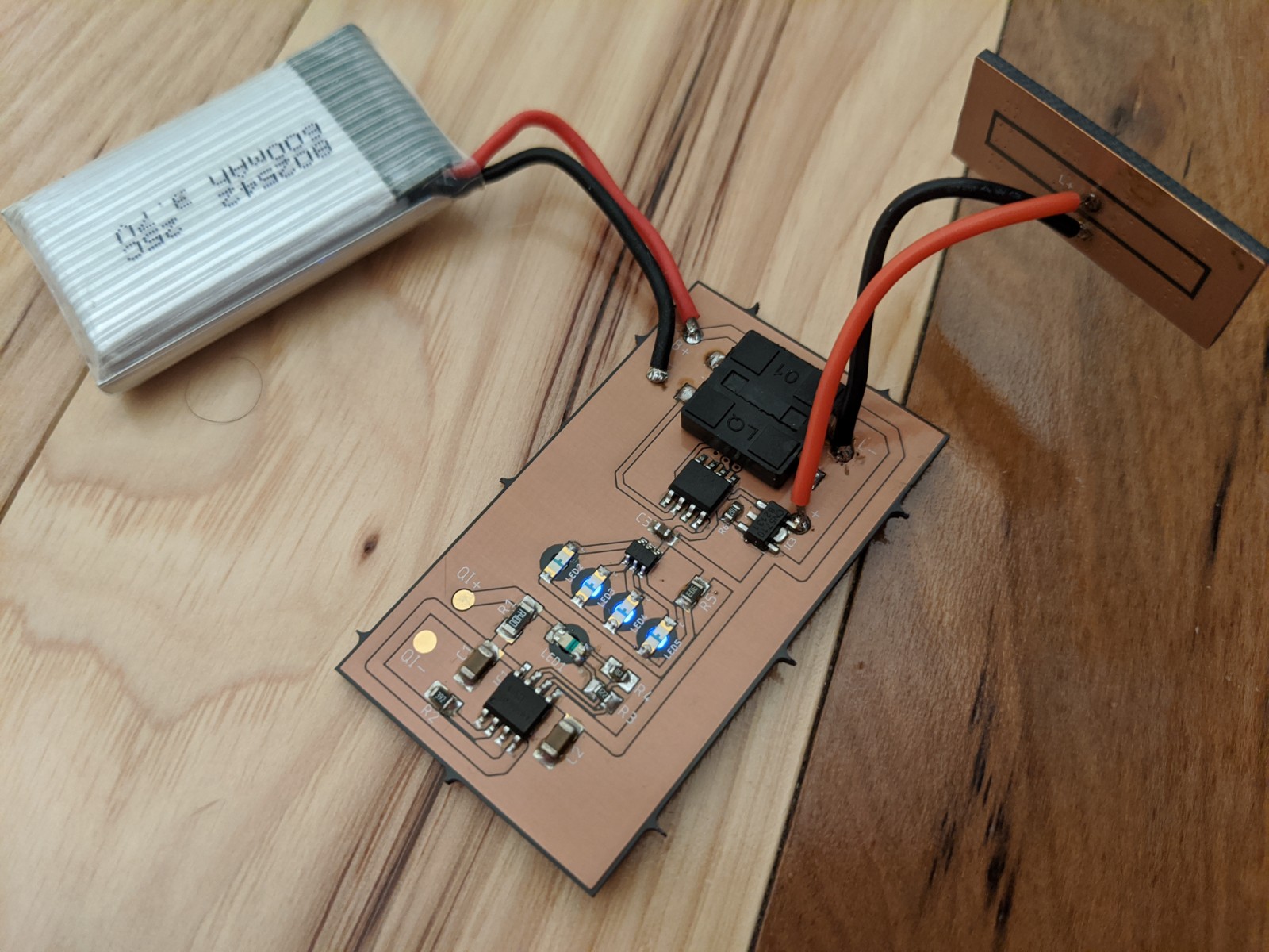
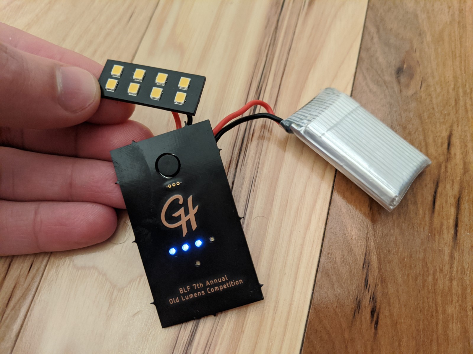
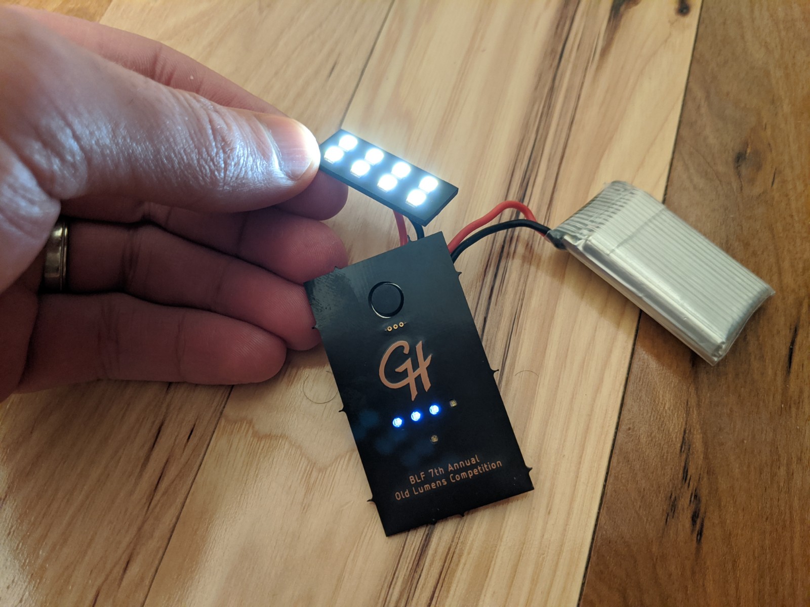
Most of the electronics have been assembled and tested for functionality. The main PCB has been assembled, along with the LEDs on their PCB. Sidenote, but the 4000K looks really good; I’m glad I went with those. I soldered the battery on (at least temporarily). The piece I haven’t soldered on yet is the Qi charging coil, thus the charging circuit hasn’t been tested yet either. Perhaps tonight.
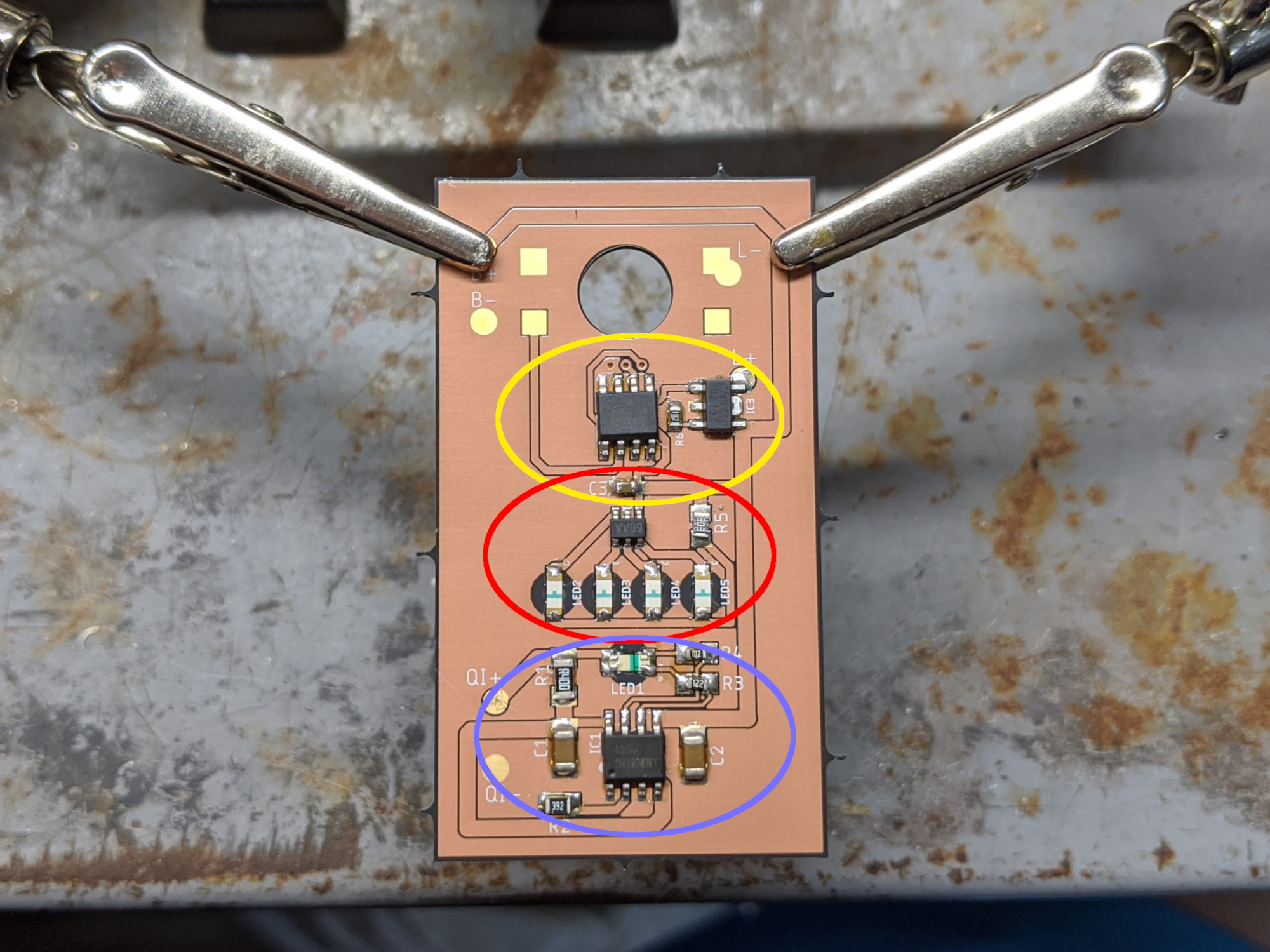
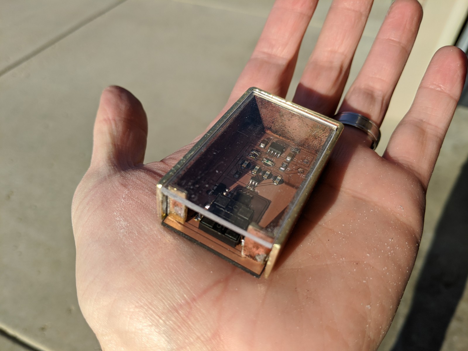
Here’s a breakdown of the circuitry (encircled in the image below):
- Charging circuit in blue: these parts were scavenged off of a standard TP4056 Micro USB charging module. The modifications here are (1) the input will come from the Qi receiver instead of the USB port, (2) the current set resistor was swapped so that the charge current will only be 300mA instead of 1A, and (3) the indicator LEDs were replaced with a single reverse-mount red/blue LED.
- Battery indicator circuit in red: this is the same HM1160 circuit used in my recent LED tailcaps. This is a really easy-to-use IC with minimal part count. I used blue reverse-mount LEDs for this.
- Main control circuit in yellow: the brains are an ATtiny412 running RampingIOS (D4 V2 UI) which are controlling a CN5710 which is set for 1 amp. The UI is currently stock, but now that I know that everything is working fine, I’ll be doing some customizations like re-arranging the multi-click options and implementing a “hold for low while in lockout” feature using the exposed programming pads.
Next up: (1) test the Qi charging circuit, (2) form the brass casing
Cool! I love it ![]()
![]()
I have to agree with MtnDon whether I like to or not. ![]()
CN5710? It’s nice to see more use of this regulator. ![]()
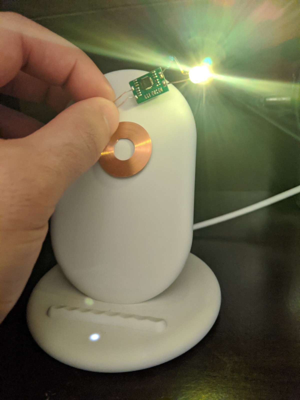
Wireless charger tested and installed, verified operational. The Qi wireless charger PCB didn’t have polarity marked so I tested it with an LED and resistor to make sure I had it right before installing.
Polarity test:
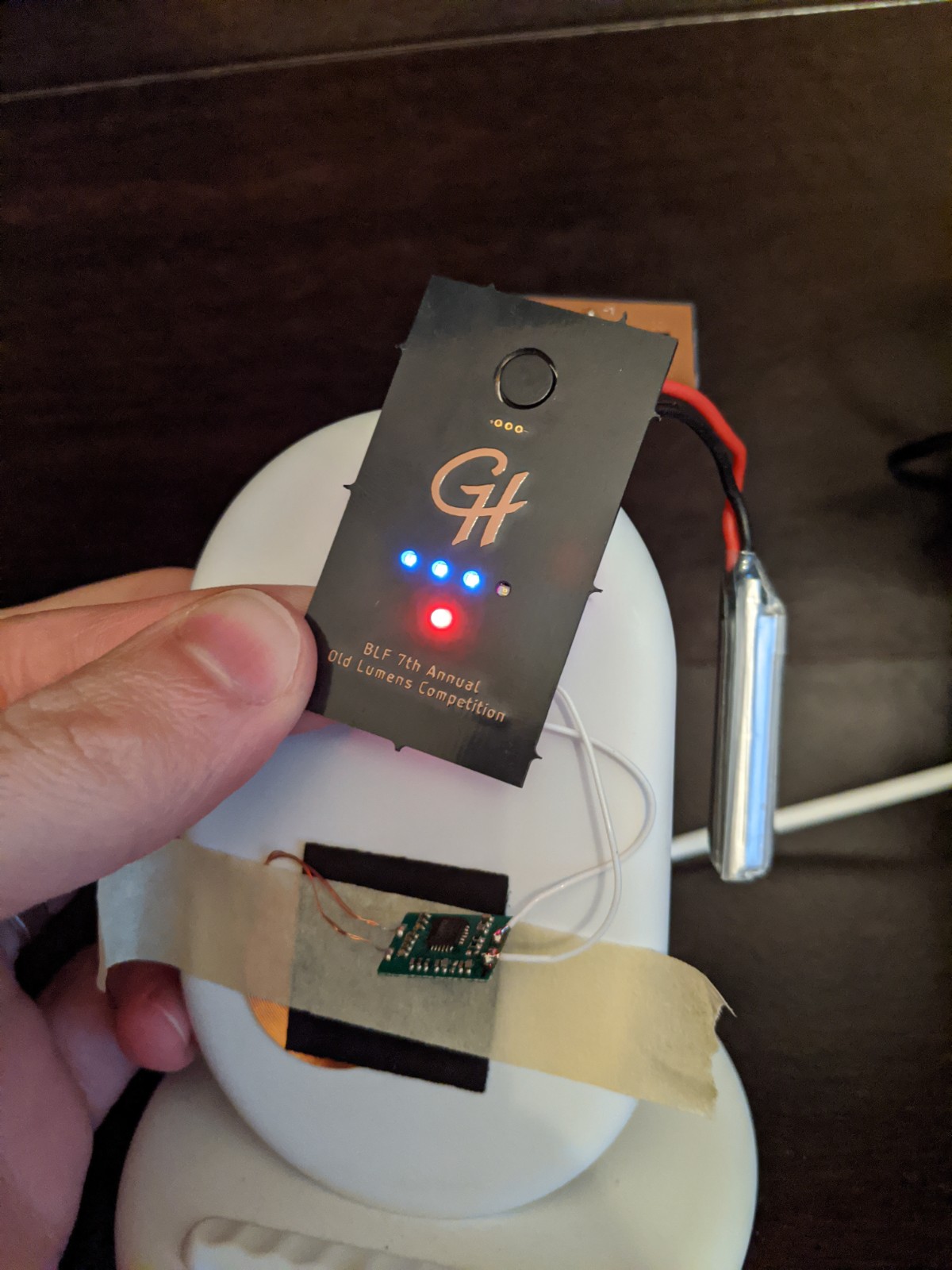
Charge begin (red):
Charge complete (blue):
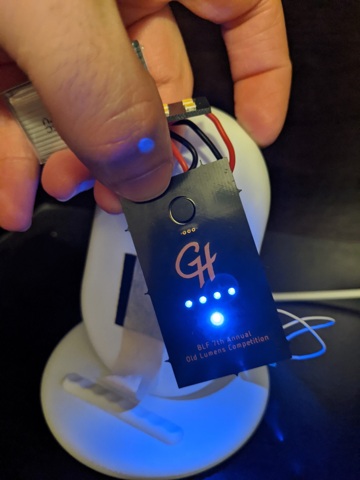
With this, I have what is likely the first bi-color LED that I can properly see. I’m colorblind and it seems like everyone uses red/green. Finally, a red/blue charging indicator!
![]()
Clever. ![]()
Wow, first light with wireless charging. Awesome work gchart ![]()
Indeed!
![]() Cool
Cool ![]()
I like it. I like the red/blue better than red/green too. Many of the green/green bicolor led’s I’ve seen have the green dimmer than the red and is harder to see.
I like the monogramming too.
![]()
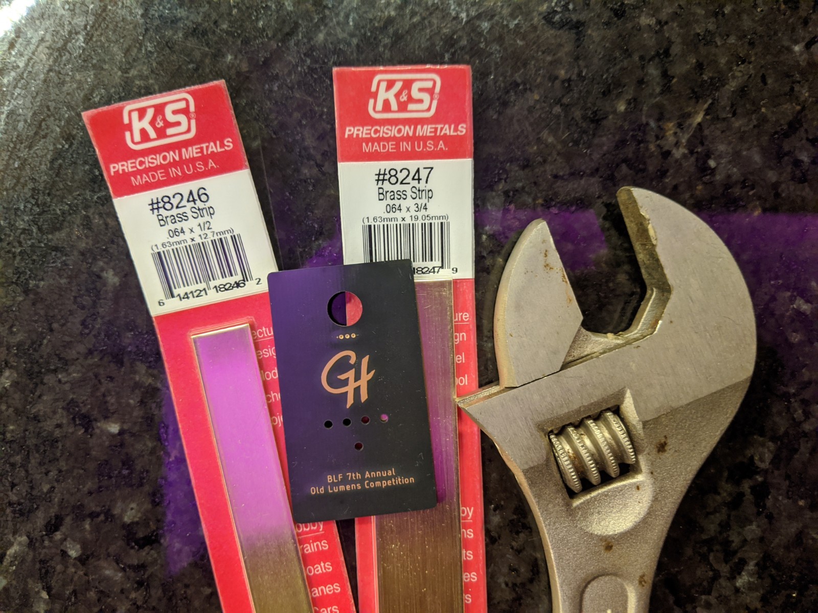
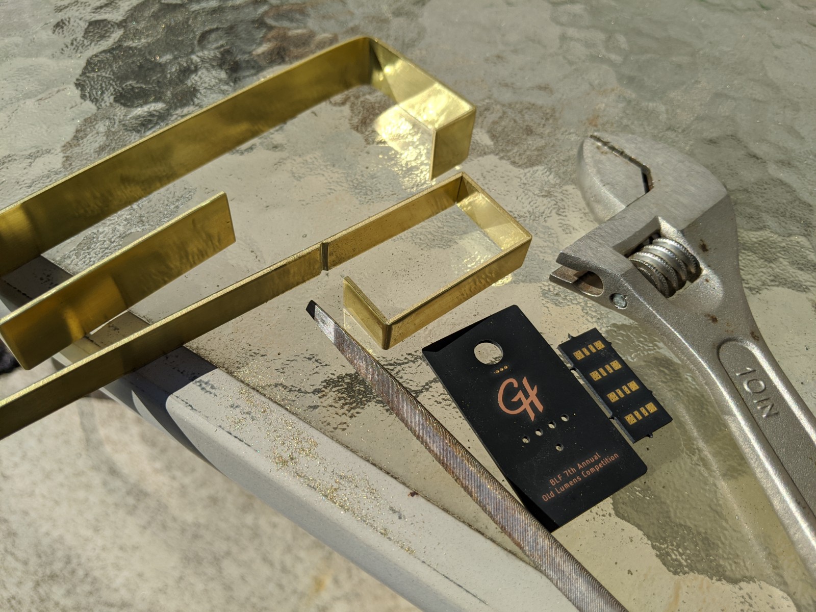
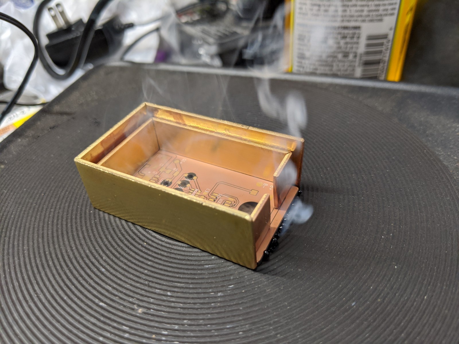
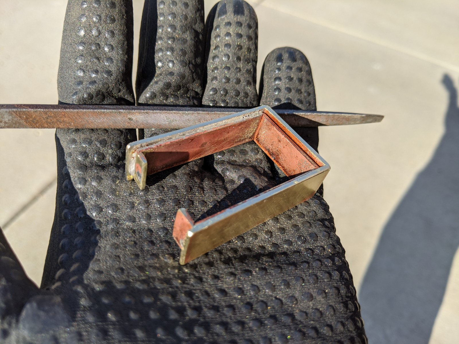
I finally got some time this weekend to work on the housing for the light. I filed, bent, and cut some brass strips. I soldered them together. Learned that PCBs don’t like ~400°C… what a stench! I cut the clear panel out of a dollar store photo frame. The outer brass stock was too wide (well, tall in the assembled aspect) and so I had to use the angle grinder to reduce the height.
Terrible smoke, good thing it was a spare PCB
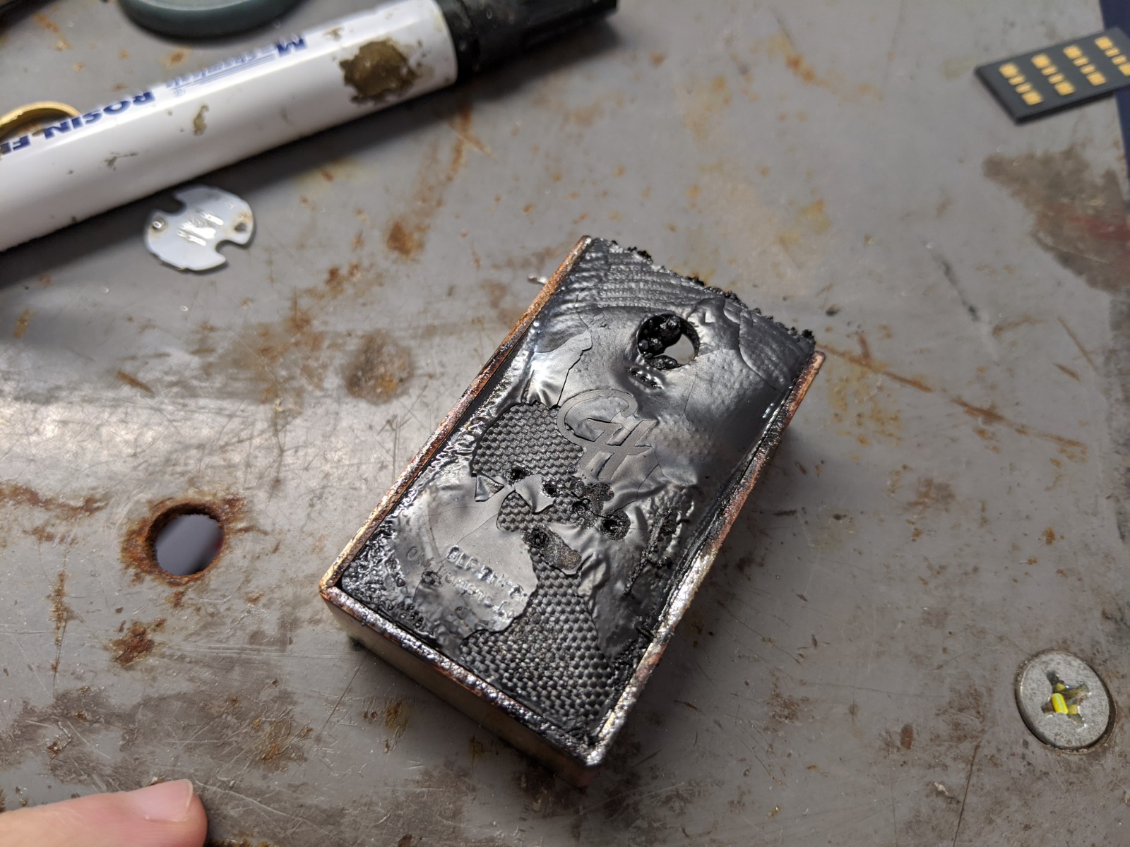
What a mess!
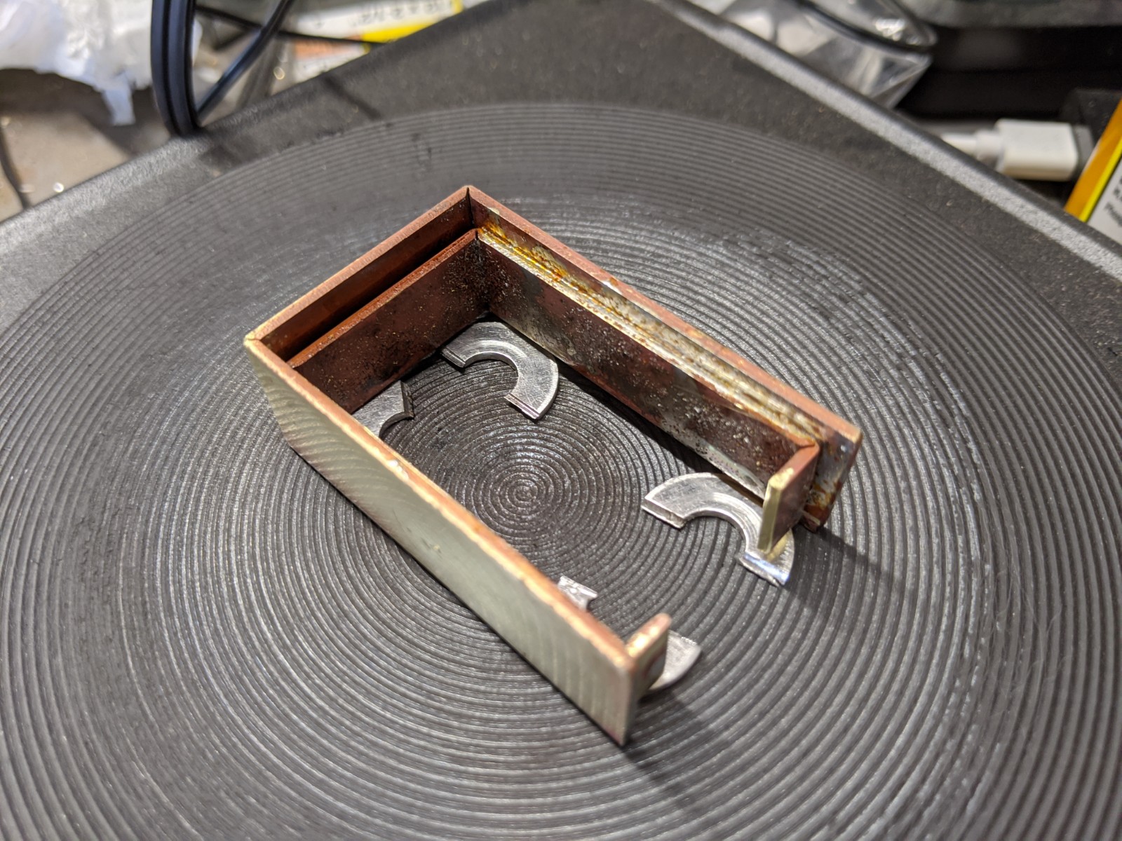
Attempt 2 - using washers this time to set the height
A bit of initial cleanup
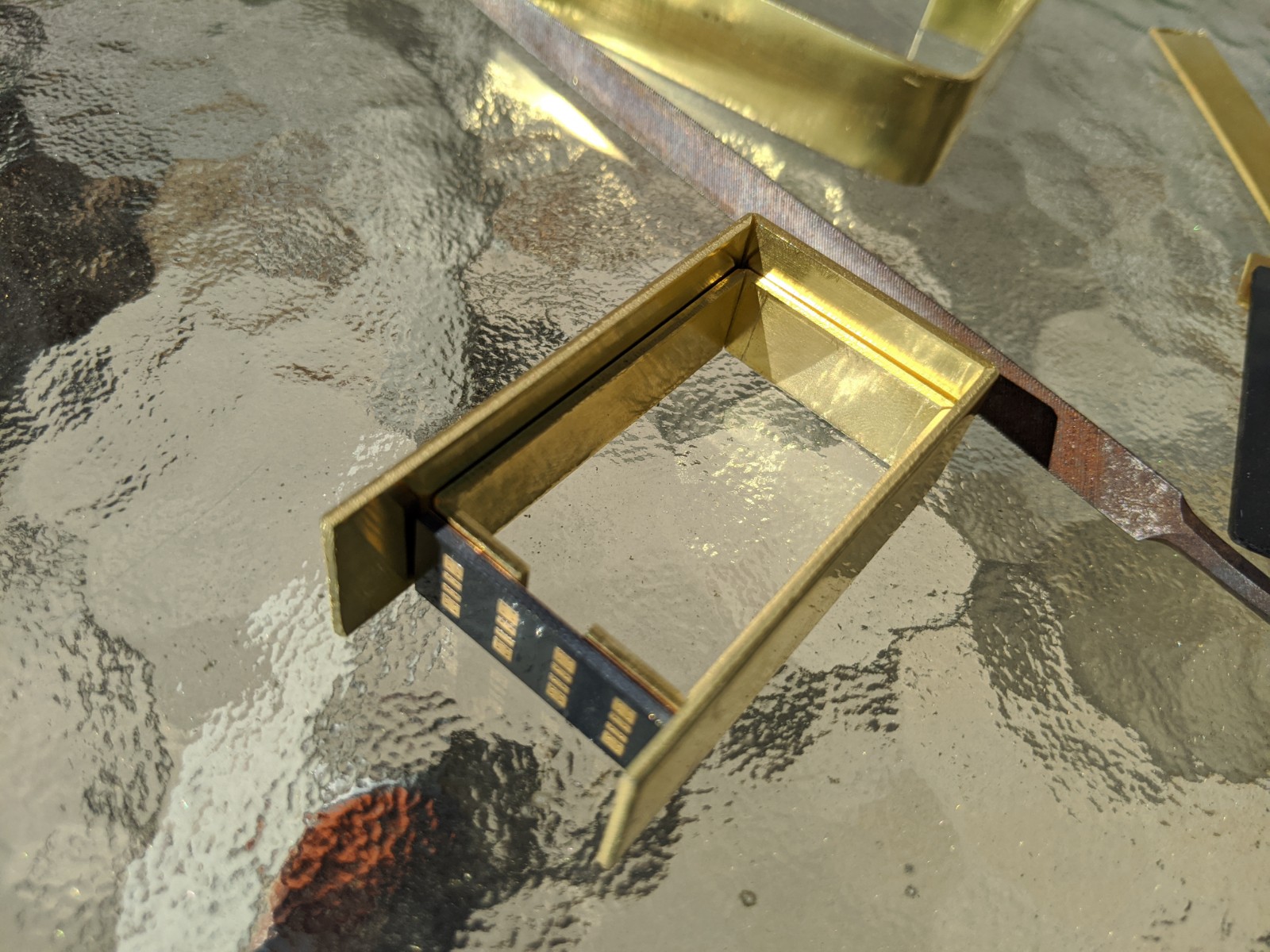
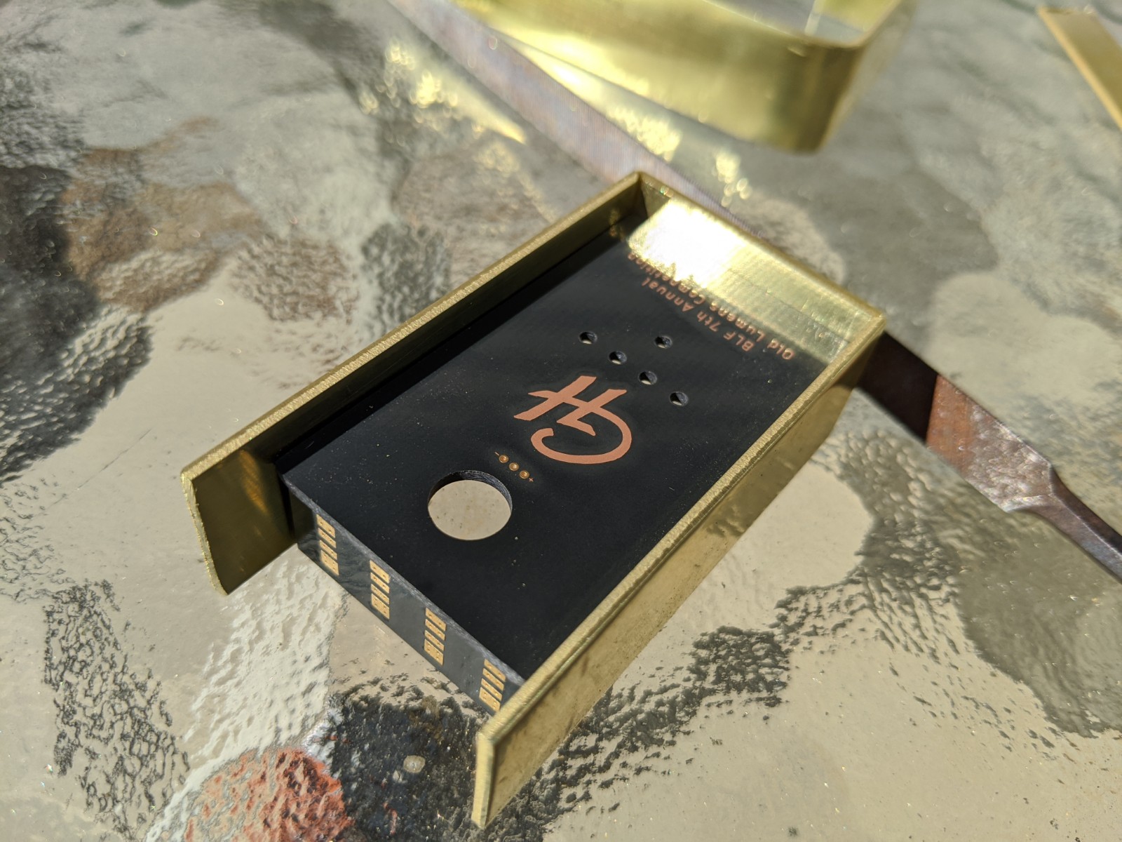
Test fit with real PCB and the window
Noice. Looks so tiny. You guys must have better eyesight than me. ![]()
Thanks Moose!
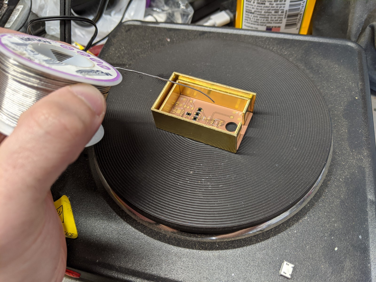
A bit more work tonight… Cleaning up the housing: some filing, smoothing out corners, lots of sanding, and a bit of a polish with some Mother’s Mag.
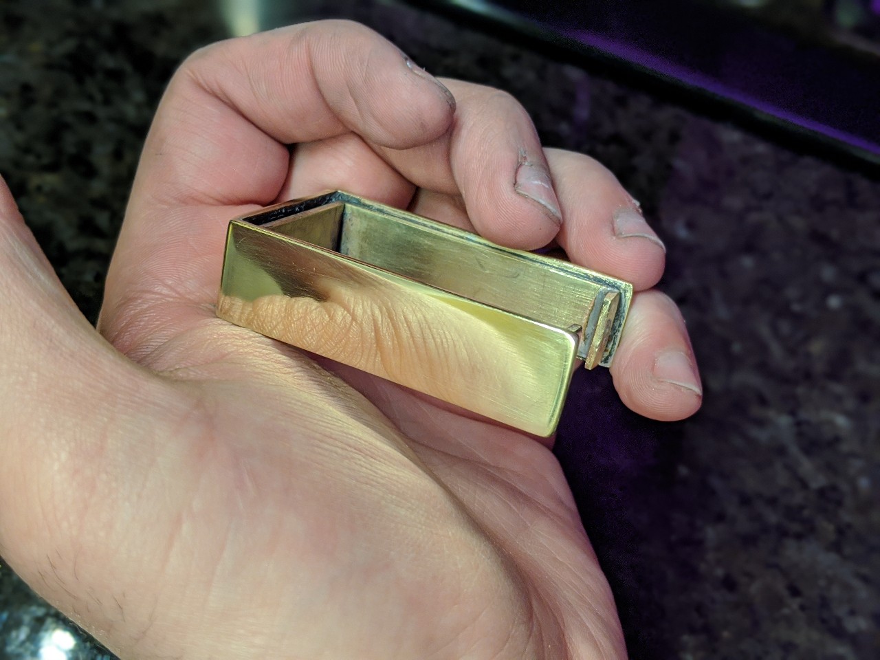
Next up: assembly!
It reminds me of Rufusbduck with the soldering and polishing.
It’s been almost a year since we’ve seen RBD. I hope he’s doing ok. ![]()