Hello,
I’m domasleo. I am pretty new to the flashlight community. I only purchased my first good flashlight (Emisar D4v2) back in June. Since then I’ve purchased a few more lights and done a bit of experimenting with customizing lights. Until now, I haven’t actually done anything serious though.
I wanted something much more powerful than my D4v2 but I didn’t want to buy something stock. I wasn’t sure if I wanted to build a fully custom light or mod a light.
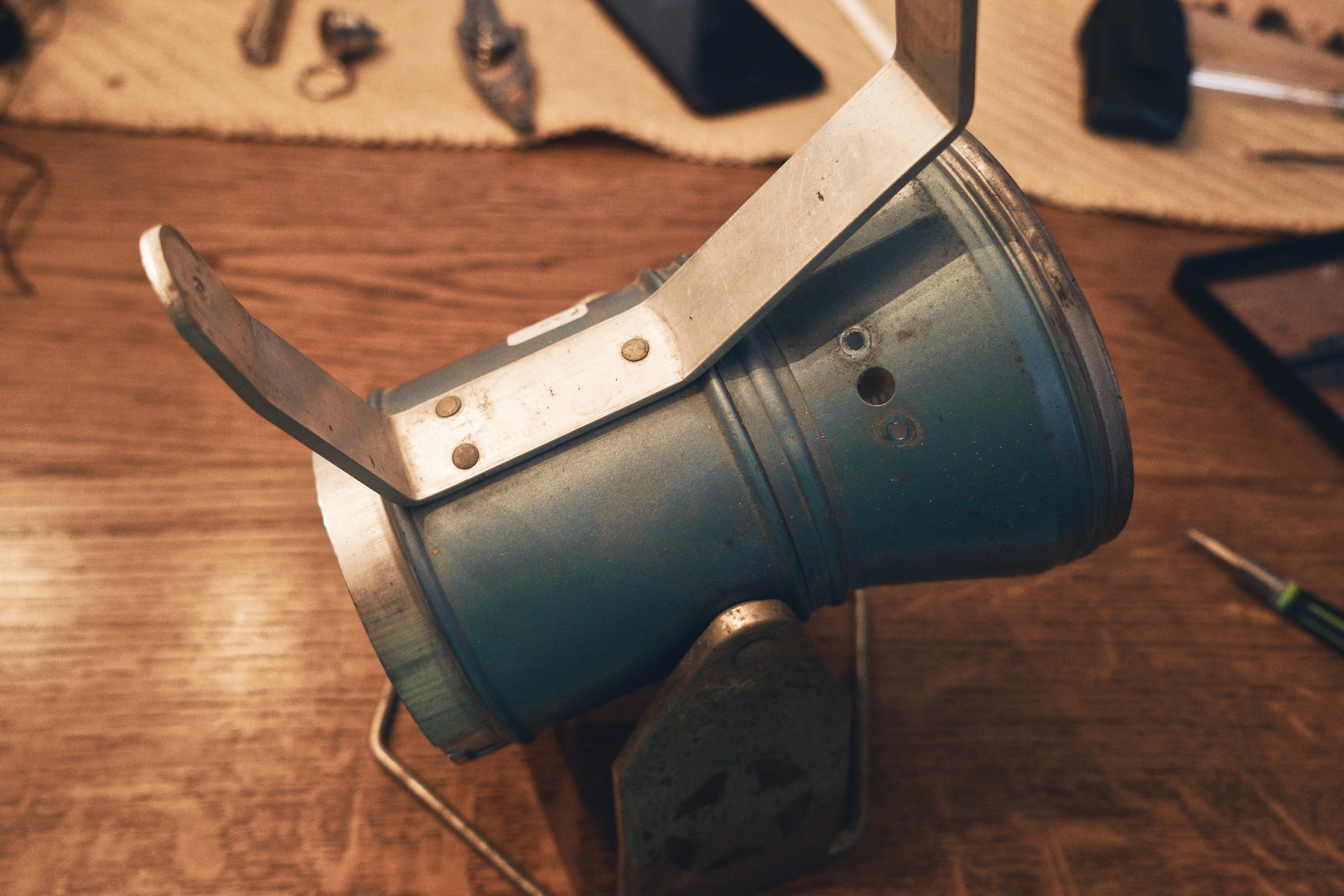
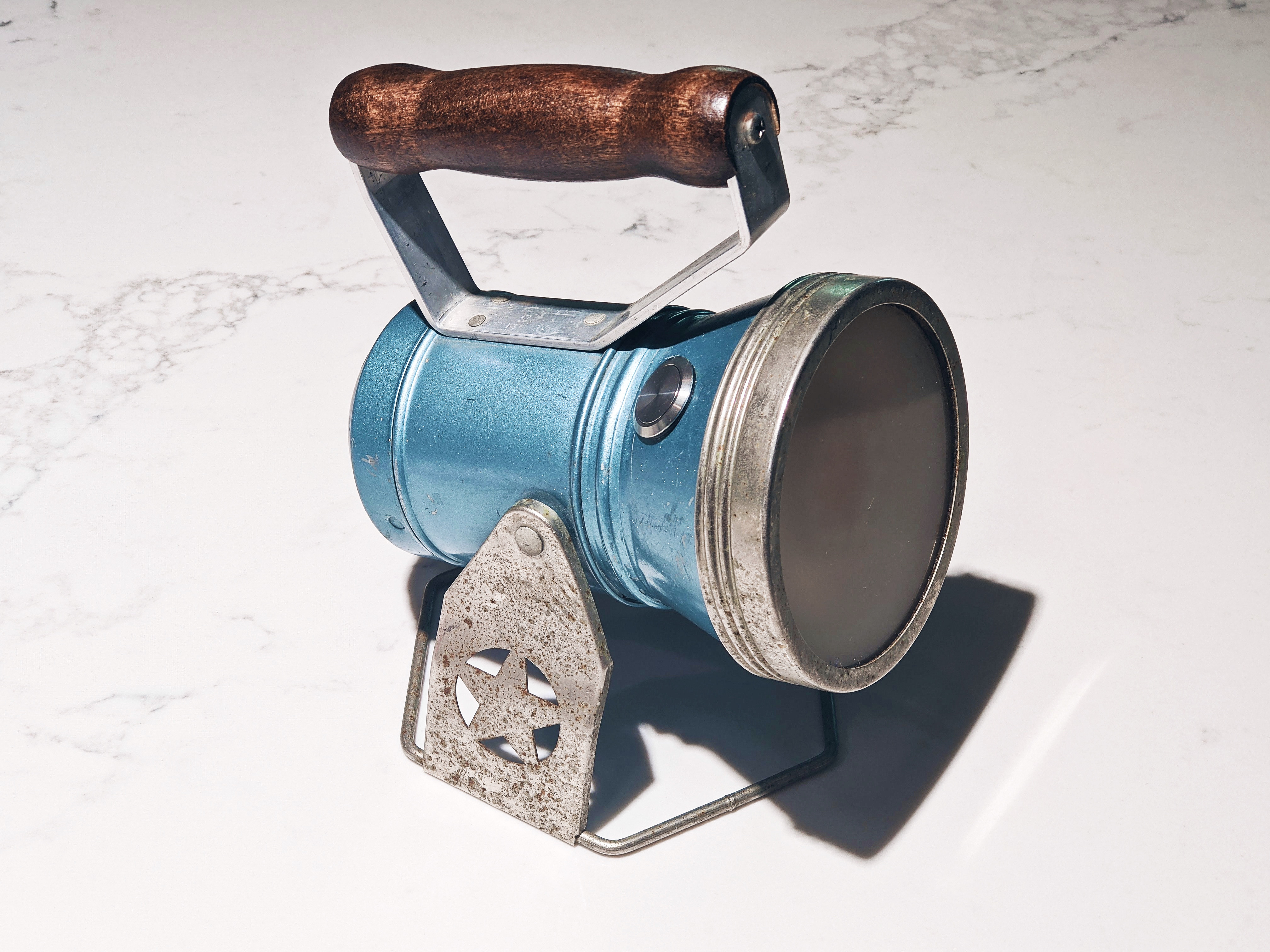
A couple of months ago I was in an antique shop and I saw this super cool lantern from around 1950.
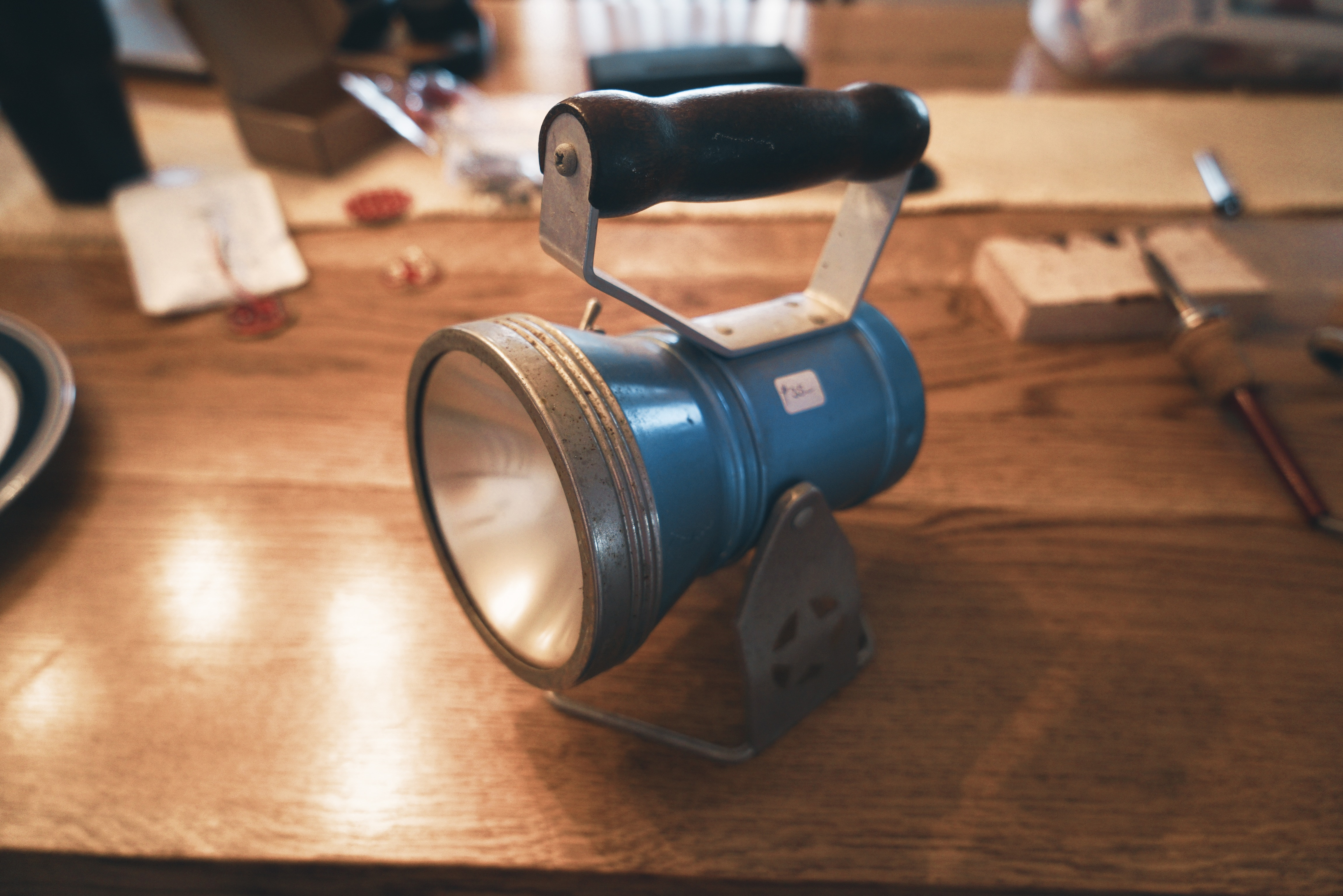
When I saw it I knew I had to have it. It was a bit expensive at $35, but I didn’t care. After getting this light I decided I wanted to mod it and make it have a really bright high-CRI warm white beam. I wasn’t sure how to do this as I had never modded a light before so I did a lot of research. I ended up deciding to purchase the internal components of an Emisar D18 and use those in this light.
In this post I’ll document the process of modding this light. It’ll go from around 10 lumens output to 10,000. I think a one-thousand-fold increase in brightness is pretty good ![]() .
.
Parts List:
The first part is the flashlight host that I pictured above. I’ll need to modify this a lot in order to fit all of the components into it and prevent them from overheating.
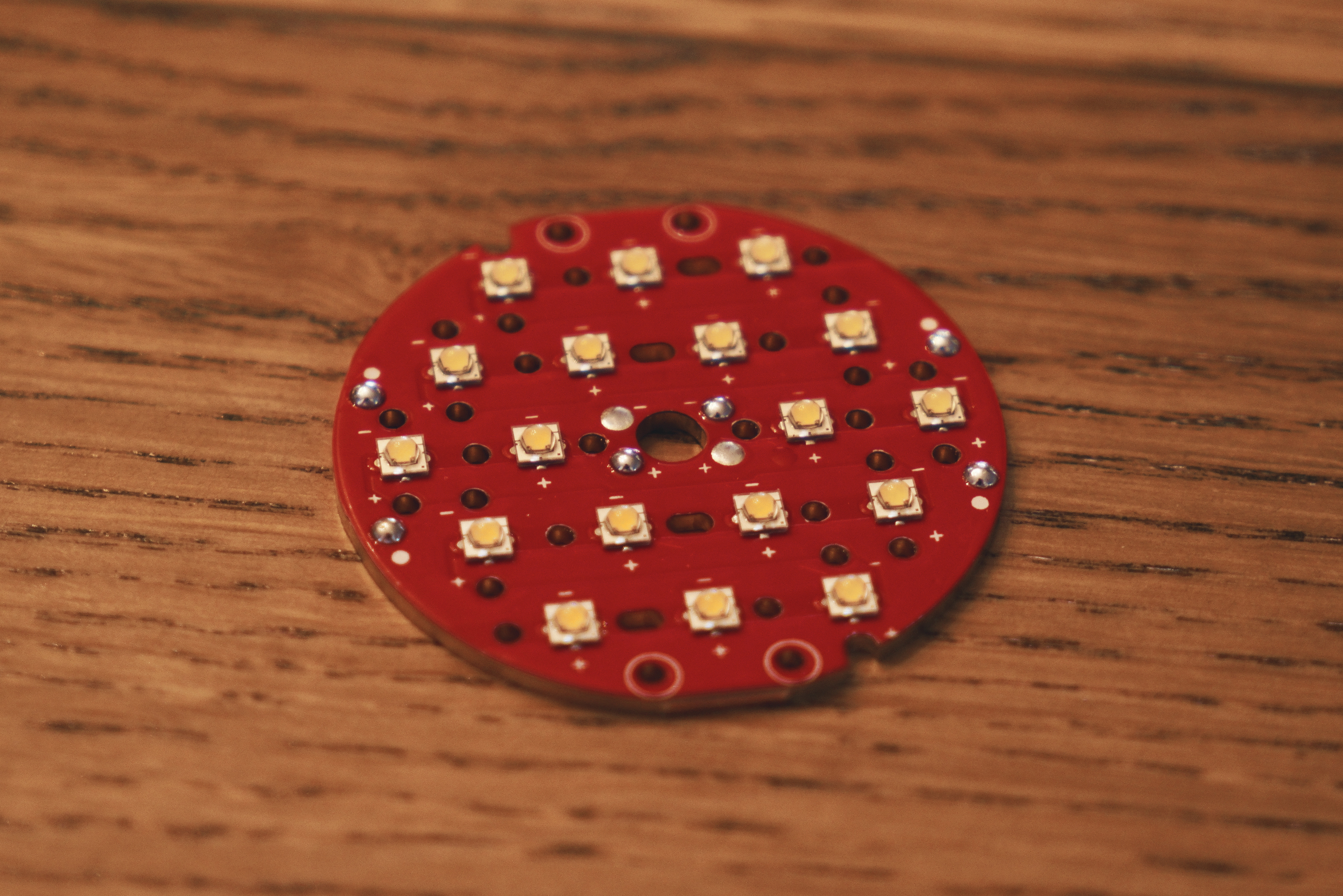
Next is the MCPCB with the emitters. I went with 3000k SST-20 emitters for a nice warm white light. I chose this because I wanted it to be similar to the original light’s color temperature.
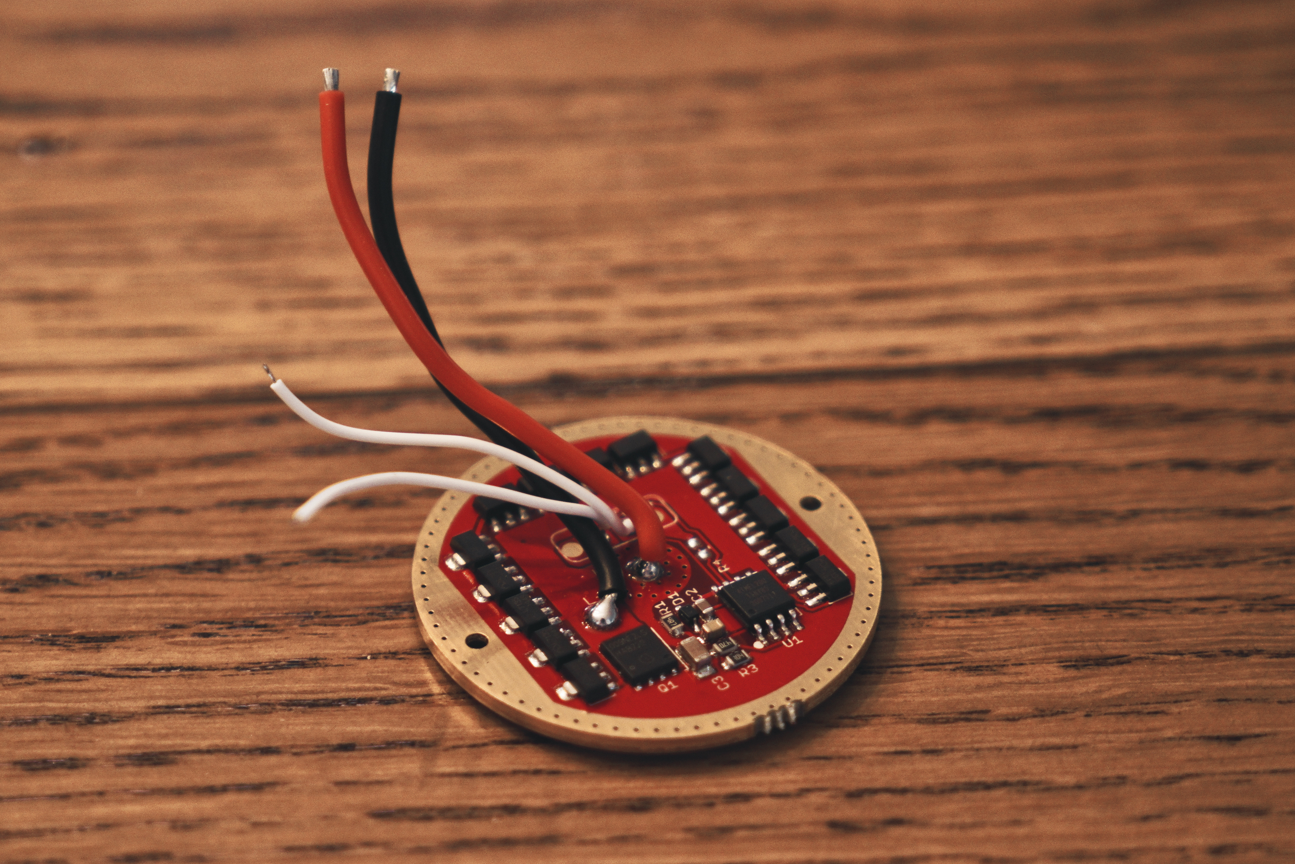
The next part is the driver board. If the PCB with the emitters is the heart of the flashlight, this is the brain. The driver controls the light, and even though the D18 doesn’t have auxiliary colored emitters, the board has pads to connect aux LEDs to so I may end up adding nice aux LEDs to this light.
The optics and reflector are obviously important parts of any light that you don’t want to have a flood beam. The light I am modding does have a reflector, but the beam was a bit floody so I’m thinking I may use 6 of the optics but leave the other 12 emitters bare so I have a slightly floody beam with a nice soft hotspot in the center. This is subject to change once I build the light and see how the beam looks, but this is the plan for now.
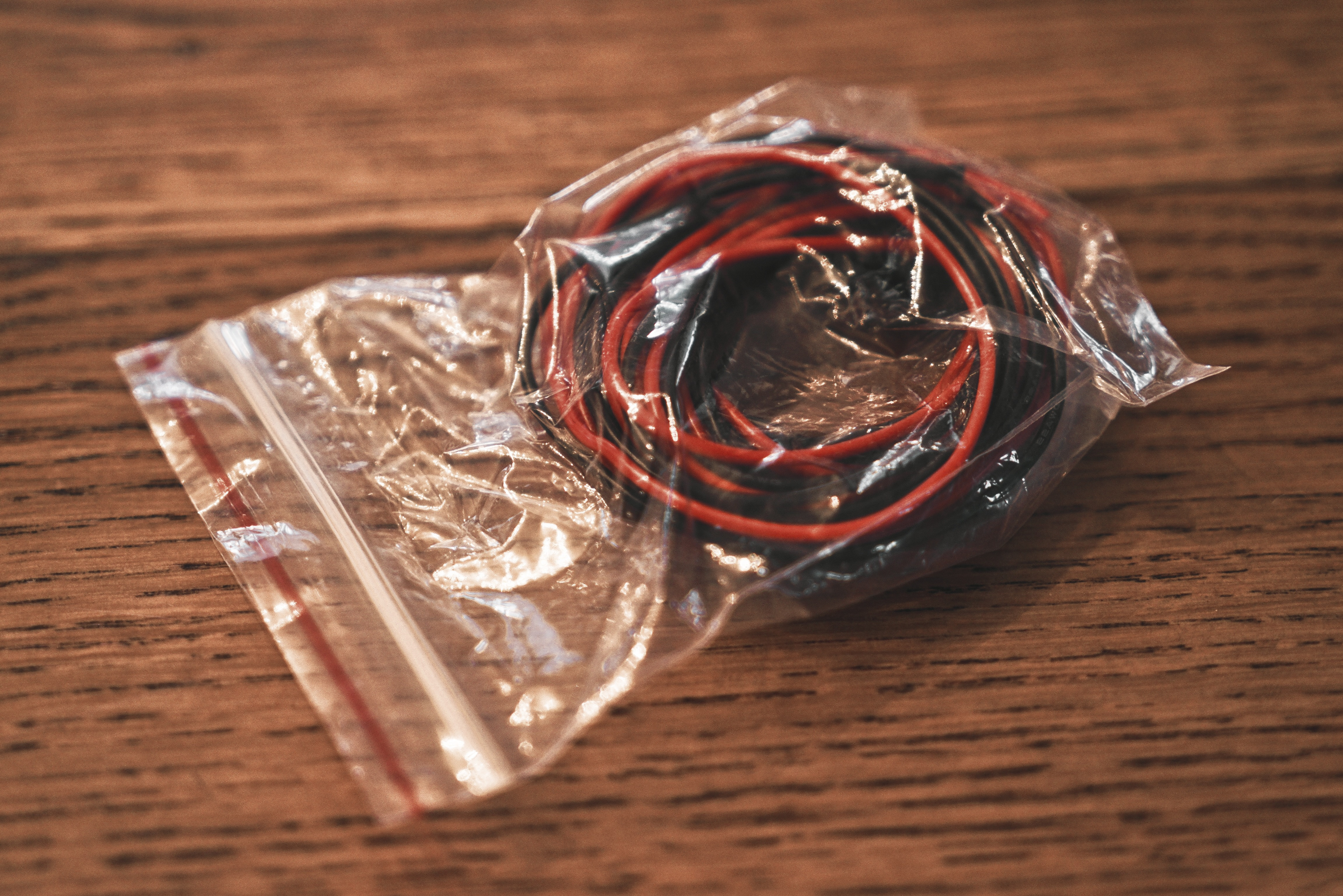
For wiring I’m using 22 AWG copper wire from Intl Outdoor. This wiring can handle up to 200 degrees so I don’t need to worry about it overheating and shorting-out.
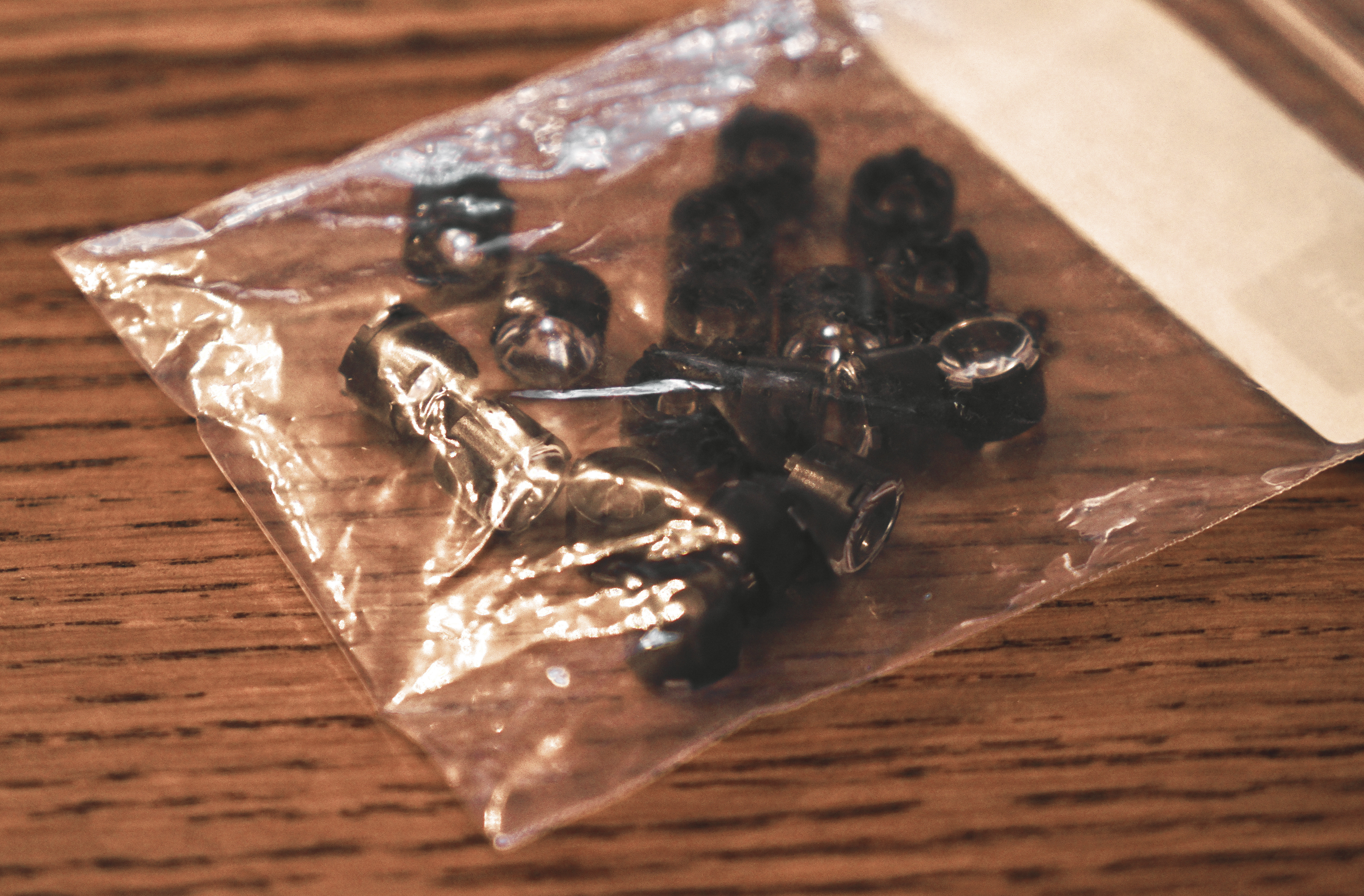
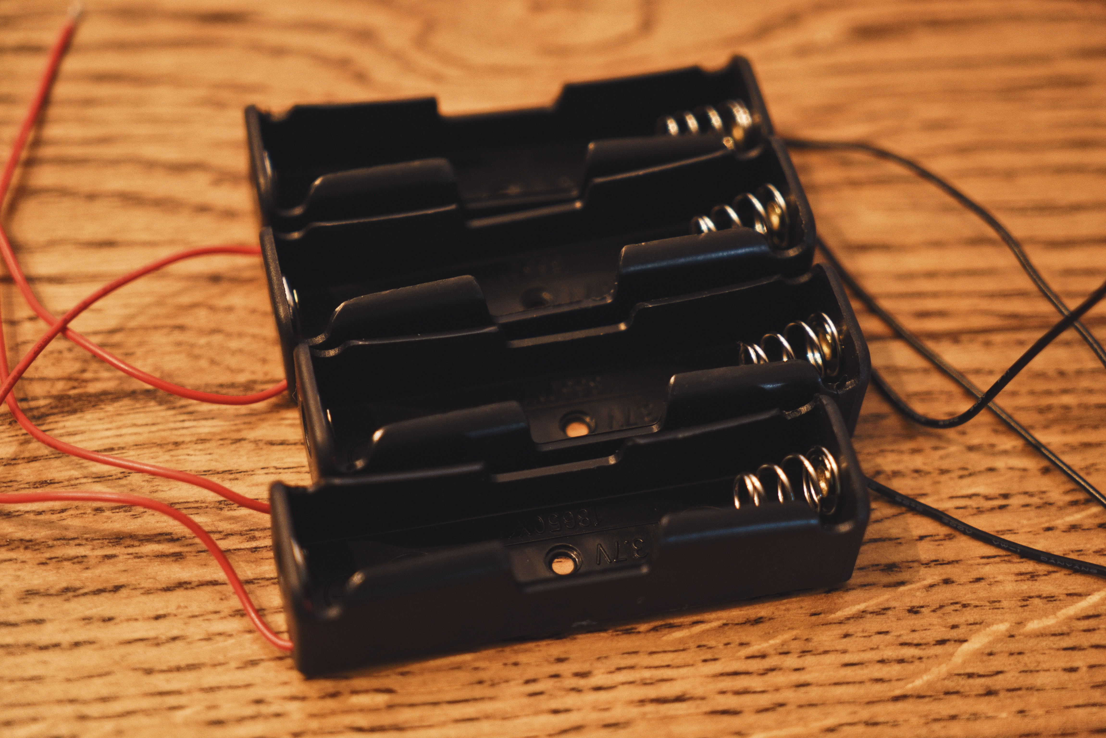
I need something to hold the batteries, and for that I’m using these cheap 18650 holders from Amazon.
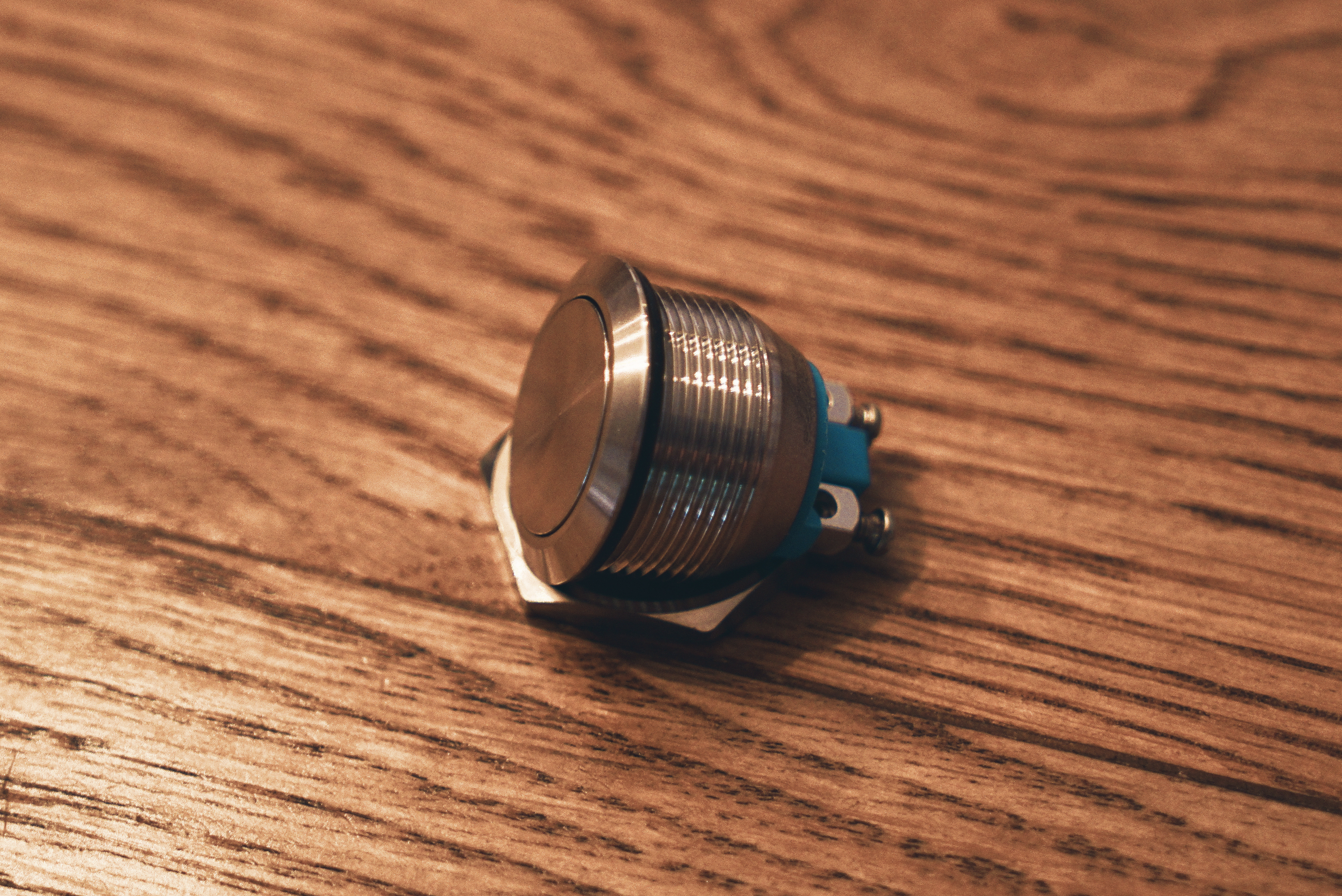
I could probably modify the switch on the host to work as an e-switch, but since it’s a toggle switch, it would be a bit of a pain to use. I decided to get a nice big 22 mm stainless steel momentary switch. The switch was like $10, but it seems to be really well made so I’m okay with the price. At this point, I’m not sure if the switch is too long and will interfere with the reflector; if it is I’ll have to mod it somehow.
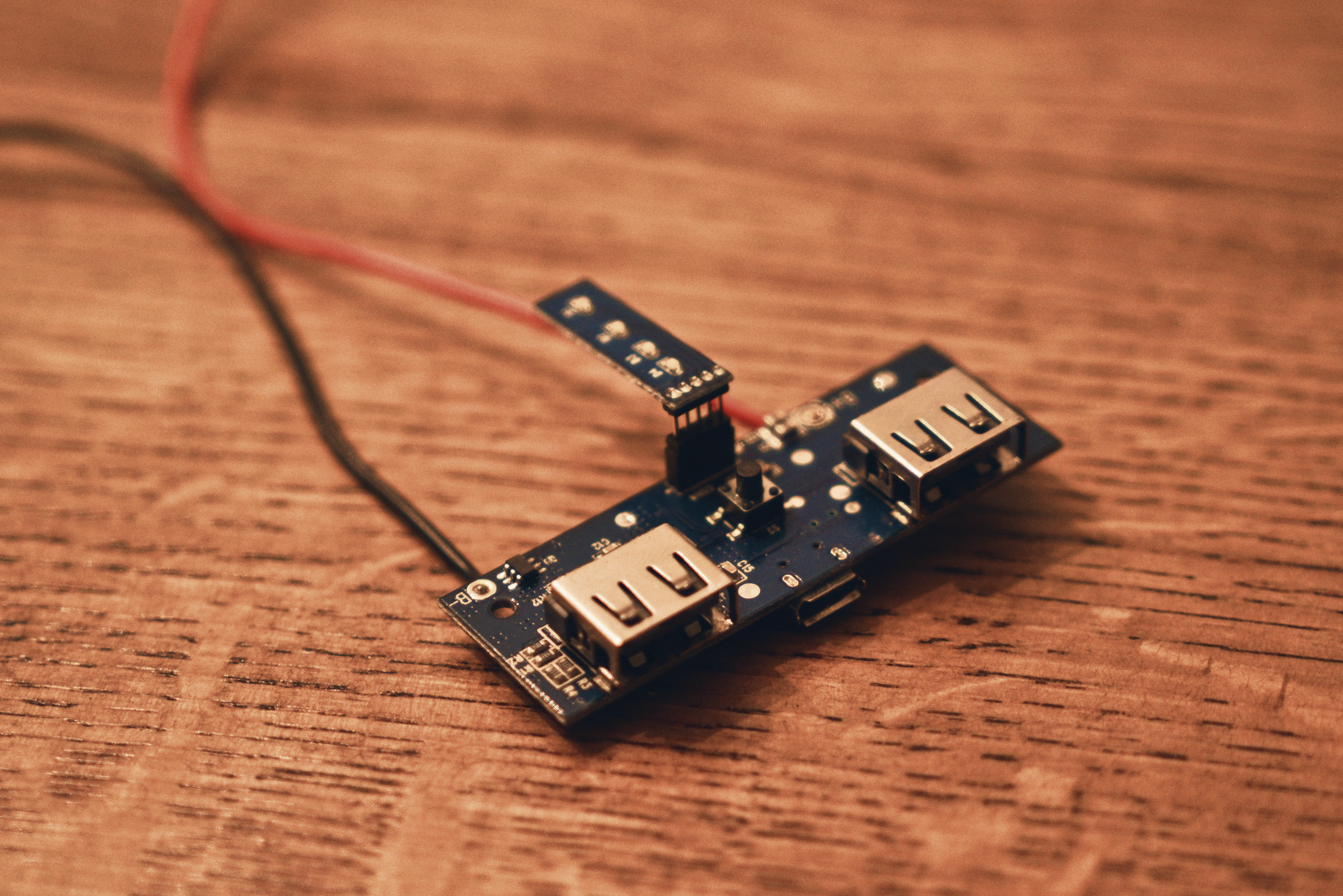
I originally planned to remove the batteries from the light and put them in a charger every time I needed to charge them, but I’ve since decided to try to wire up the light so I can recharge it with a micro USB cable. I disassembled an old power bank I had to remove the circuit board from it. This should work just fine to charge the batteries, since the power bank used 18650s, the same type of batteries the light is going to use. In a pinch I could even use the flashlight as a battery bank to charge my phone.
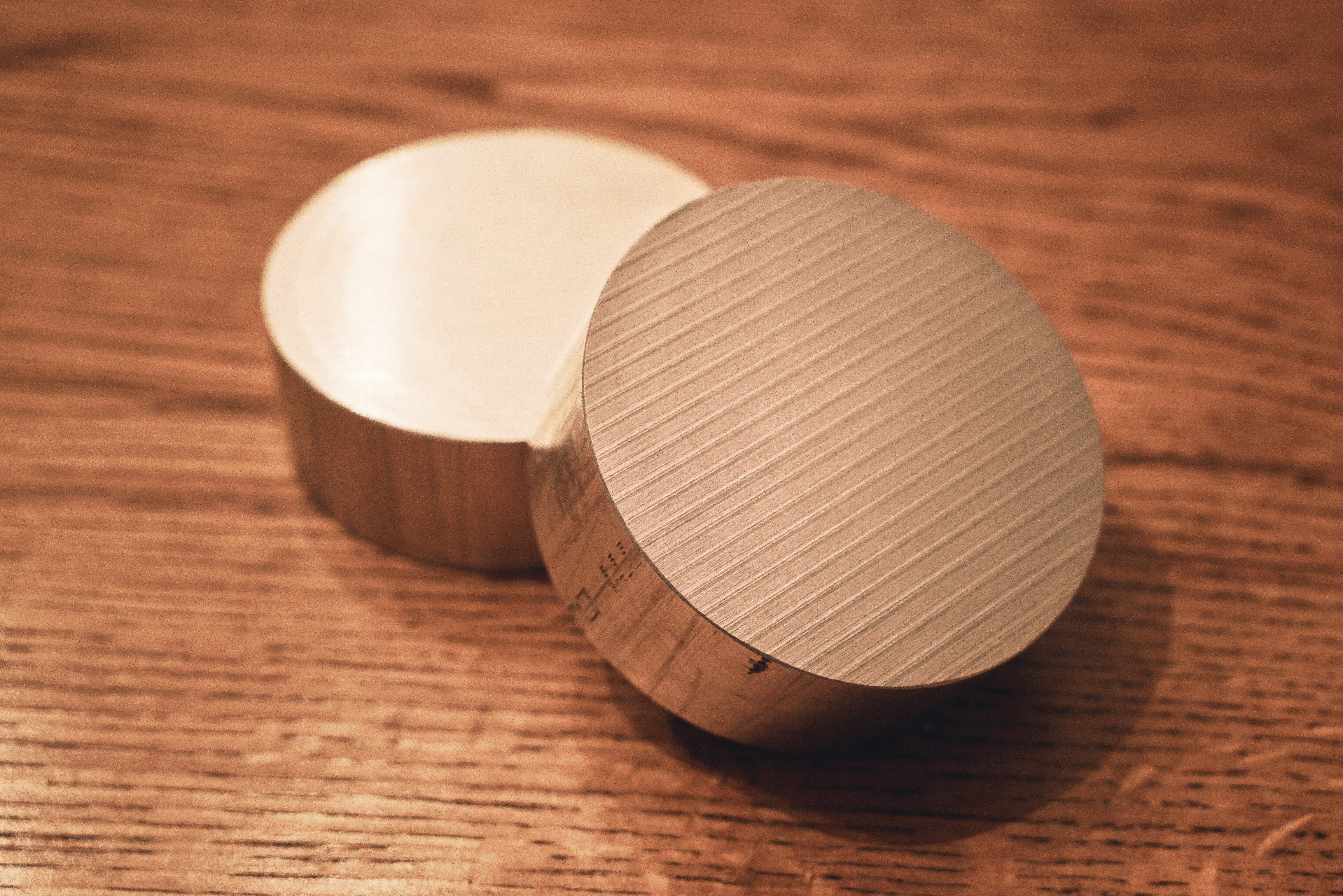
In order to prevent the emitters and driver board from overheating, I need a heatsink. For the heatsink I decided to use aluminum, because by weight it’s a better conductor than copper, and it is quite inexpensive. I was able to get two 3.25x1.13 inch aluminum rods for about $20 on eBay. This isn’t cheap, but it’s a lot less than copper would have been. I’ll probably only one one of these, but I got an extra just in case I need it. I can always use it for a future project if I don’t use it for this one.
I’m sure as I work on this project I’ll need more parts and materials such as thermal paste. I’ll update this list as I get those things.
The Build:
The first step was to verify that the driver board and the LEDs hadn’t been damaged in shipping. This was pretty easily accomplished. I needed to solder a couple of short wires to the LED PCB to connect a few pads together and then solder the PCB to the driver board. After doing this I was able to hold everything together while being careful not to short anything. I tapped the wires that will connect to the switch together and it came to life!
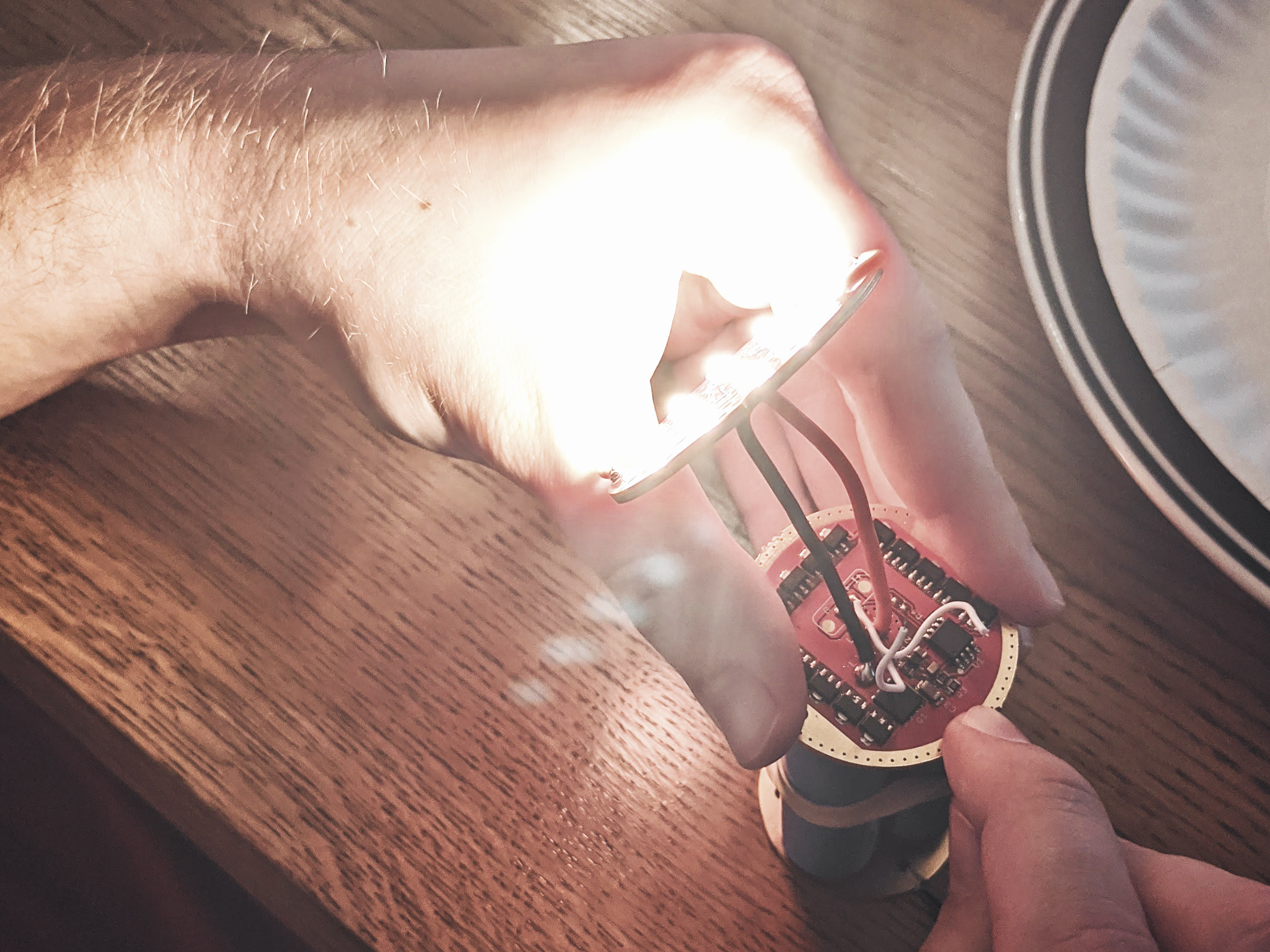
I was so relieved that I hadn’t damaged anything and it all functioned as expected. Here’s a cool photo my dad snapped for me before I had to turn off the light to prevent it from overheating.
I’m super excited about this build. The light will be extremely bright, I only had it on for a few seconds and it was enough to make me see spots for a few minutes afterwards. I wasn’t even looking at the light, it was just in the corner of my eye.
While I was waiting for more parts to arrive I decided to start to disassemble the host so it would be ready to clean and add the components to. I was able to remove the wooden handle, the switch, and the lens/reflector. You can see in this photo that it’s fairly dirty, but what else can you expect from a light that’s about 70 years old? ![]()
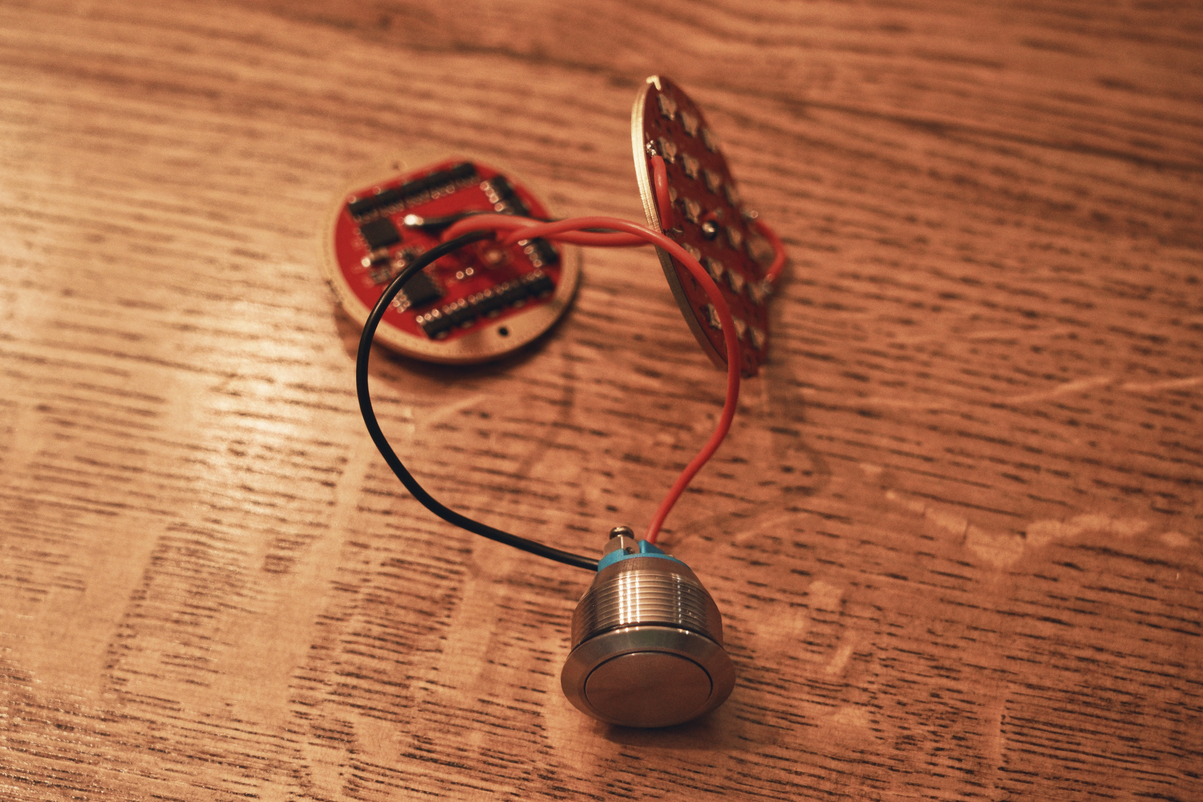
Next I soldered longer wires to the driver board to connect it to the switch. I hooked the switch in so I could give it a quick test and it worked as expected. This switch is going to be really satisfying to use, its big and nice and clicky.
After this I soldered the wires for the battery holders together to the wires that will connect the batteries to the driver board.
I also cut part of the holders off so the batteries could be removed from them easier. I’m not planning on removing the batteries often since the light will be USB rechargeable, but I’d still like to be able to remove them fairly easily just in case I have a reason to remove them. (I temporarily covered the solder joints with duct tape so they wouldn’t short, I’m going to replace it with electrical tape once I get some.)
Now onto the heatsink. I needed to drill a hole through the center for the wires to go through. The hole in the LED PCB is about 3/8th of an inch but I decided to make the hole through the aluminum 1/4 inch so the wires wouldn’t be pinched at all.
Here’s a couple of photos from after drilling this hole. In the one photo I’m holding a Folomov EDC C1 for size comparison. This is a 10440 light, so it’s pretty small, but it still shows how this is a pretty large piece of aluminum.
Next I needed to drill four small holes in the aluminum for the screws for the PCB to go into. For this I used a 1/16 inch drill bit since the screws I’m using are very small.
Here’s a photo showing the PCB sitting on the heatsink with arrows showing where the screws will go.
Now all that was left to do is the final assembly of the light! I considered soldering in the heatsink and driver board but I wanted to be able to dissassemble the light in the future so I could upgrade it so I decided on using a bunch of hot glue to hold everything in place. It’s not pretty, but it works good so I’m happy with it. Once all the components were inside the host it was time for a test!
I can’t tell you how awesome it felt to power this light on for the first time. It looks about twice as bright as my previous brightest light (an Emisar D4v2) and it has a really nice even beam. I wanted a slightly softer beam so I removed a few of the optics and used some matte clear spray paint to make the lens slightly frosted. It now has a really soft beam , it’s almost a floodlight.
Here’s a picture of the finished light!
I still have work I want to do to the light to make it even better such as adding tritium tubes and removing rust from it, but I’m really happy with where it is right now. I think it turned out pretty good for my first flashlight mod. It wasn’t easy and it took ages but it was worth it imo. Good luck to everyone else who entered the competition, I look forward to looking through all of your threads!