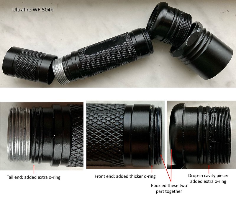
The host is an Ultrafire WF-504B. I’ve made some improvements as can be seen in the photo below.
It had extra slots, not sure exactly what they are for, but I put some o-rings on them. Can’t hurt, right?
I was also a little disappointed to find out that the drop-in cavity piece and the battery tube are two pieces, which is to save cost of course, so it makes sense for a $14 host that comes with a drop-in. There are only like three threads on that piece, and there was a very thin o-ring, and water was coming right in. I replaced with a thicker o-ring, and epoxied the parts together.
Here is the drop-in it came with: cool white XM-L2 and H~~M~~>L->strobe. Actually it’s not bad, but I might have to do something with it after I finish the quad.
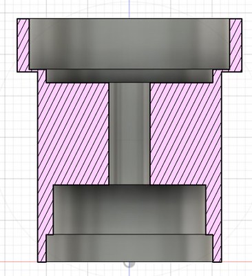
I’m basically a beginner when it comes to 3D modeling and 2D drawings. I’ve likely made a mistake and any feedback is welcomed.
I do think that the driver cavity can be a little less deep than in the model above. The tallest component on the driver is only ~3 mm (which I believe is an inductor). However, the wires also need some clearance. I’m thinking about making it only 4 mm deep, and chamfering the bottom of the through hole to provide extra clearance for the wires, which seems like it would be needed at the center, if anywhere.
Here is the idea shown below, which increases mass from 59.3 g to 63.4 g.
You might also be wondering why the MCPCB cavity is 3.5 mm deep when in fact it is only 1.6 mm thick (planning to use MTN 20 mm quad board). Initially, I modeled it as 1.6 mm deep, and a section of the drop-in got really, thin, only 300 um. I took some measurements on the assembled Carclo optic, and I believe it will work as shown.
Here is what it looked like originally. Glad that I made a solid model, although if I were smart I would have checked for issues like that with paper/pen/calculator.
Played with the feeds and speeds, but was getting terrible surface quality. In the past, I’ve machined 360 brass, which comes out great pretty much whatever you do to it. In this case, I’m working with basically pure copper, for its thermal conductivity, and it is very ductile. The material coming off would not chip away, but would scratch up the rest of the part.
Keep in mind that I’m a beginner machinist and am learning as I go. It was at this point that I started to regret this project. I could have bought a really nice flashlight for what I spent on these materials…
But then I tried some cutting oil that I found in the shop, and the result was 100% better.
Nice work. I’m not machinist either, but I have found that ~400rpm works ok in most cases with copper. And small passes. If it heats it becomes sticky.
Thanks for the tips. I did struggle with heat a little. I didn’t note the rpm but was able to take off up to 500 um from the OD per pass, with a fairly slow auto feed rate. Then of course much less per pass as it got close to the final dimension.
For sure, that would make a nice addition to your workshop. In this case, I have permission to use an old but still nice manual Hardinge. It’s been a great experience.
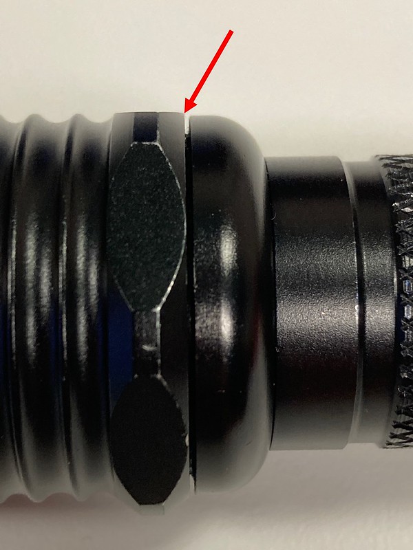
First added a notch on the top of the shell, to more easily remove the optic with tweezers or a small screwdriver. I have one light where it is virtually impossible to get the optic out, even with tape, vacuum pick, etc. This should simplify that process.
Test fit. The gap between the two pieces means that the shell is long enough, and it makes contact with the battery tube when the head is tightened down. If there is nothing in the head, those pieces tighten down with no gap.
Here is a photo from MTN Electronics of their quad board in 2s2p configuration.
I followed that, and reflowed the LEDs (219b from Convoy). I used 3x 4500k and 1x 3000k to add a little warmth.
Then soldered the LED board to the shell.
After that, things went awry. In the past, I always soldered the driver to the pill, with single emitter drop-ins and even a brass triple that I made. I figured that even though copper is more conductive than brass, in this case it is pretty thin at the edge due to the 20 mm driver and wouldn’t be an issue. I couldn’t do it, so I will have to solder a ground wire to the shell instead. This is the aftermath. The shell acted like a crucible for the liquid solder, and never stuck.
Whispering, in my experience soldering to copper you have to expect to heat the entire part to the desired temperature. For me, I put stuff like that on a hotplate. So the hotplate might be set to 200C to preheat the pill so I could solder to it.
I have also found that it can help a lot if the large copper (or brass) piece is pre-heated by itself, and then a small amount of the solder is applied to the fluxed position on the rim where it is desired to solder the driver connection. Enough solder to “tin” the spot with a little extra, but not too much to flow where you don’t want it to be. Then when the pieces are assembled it does not take so much heat to affix the driver rim. A big enough soldering iron with a tip that provides maximum surface area for rapid heat transfer also helps.
Thanks to you both for the tips. I’m always worried about overheating the driver or LEDs, especially with such a big chunk of copper (i.e. lots of heat needed). I also feel that it’s essential to solder the MCPCB to the shell, so that complicates things. I’m sure it is possible, but I’ve been working on using a wire instead of soldering the driver directly to the shell. I hope to post a finished drop in soon.
I’m also working on bypassing the tail spring. Only 30 days to go…
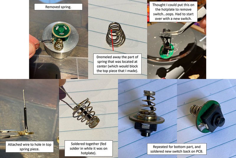
Here is what I ended up doing to bypass the tail spring. I wanted it to be secure, so I machined some little discs with holes to feed the wire through and twist together/solder. The wire is 22 gauge, hopefully that is enough. I’ve also read that it is better to have a button on top of the spring for better contact with the battery
Here is the assembly process.
It was a bummer that I ruined that switch (a Solarforce forward clicky with nice action). The switch was a little long though and it prevented stable tail standing. I had some Convoy switches that are much shorter, to the point that it can’t really be clicked when assembled. The boot has a little protrusion that is too short to reach the end of the switch. At first I tried printing a TPU boot with a longer protrusion, but it was too stiff. Instead, I printed a PLA extension that fits onto the boot and makes contact with the switch.
Machined a new shell. On the old one, I was trying to solder a ground wire to the bottom of the shelf, but the solder ended up everywhere and looked messy, so I wanted to start fresh.
Here is a video of test fitting the drop-in (this is with the old Solarforce switch I had before I melted it, which is why it doesn’t tail stand very well).
There is very little clearance, so air is slow to escape between the outer wall of the shell and inner diameter of the host. The shell bounces back up because it compresses the air inside the tube (battery was also inserted at this time). The video is from before the shell was finished. It doesn’t have the through hole or LED cavity yet (otherwise air would escape through the center hole).
I’m hoping for adequate heat transfer due to the tight fit, without the need to wrap with foil or copper tape. In my opinion, wrapping a drop-in kind of negates the main benefit of P60, which is changing the emitter/UI/beam pattern as easily as changing a battery. I can’t know for sure if a tight fit such as this, while maintaining easy interchangeability leads to an actual improvement in heat transfer, or how much of an improvement it is, because I don’t have a way to test it.
To make the drop-in easy to insert in the host, I added an air relief groove.
And since I had trouble soldering the driver to the shell on the first attempt, I drilled a hole to solder a wire the shell. This seems like it should be more secure than soldering to the bottom of the shelf. Theoretically, it could also allows for a thicker shelf, rather than creating a bump that might require more clearance to prevent interference with the driver, although I probably don’t have the dimensions optimized to that point. I also dislike the idea of soldering to the inside surface of the driver, so I’m running the wire up to the outside.
The wire hole is oversized because I had difficulty drilling small holes in copper, when practicing on a scrap piece, breaking a couple drill bits.
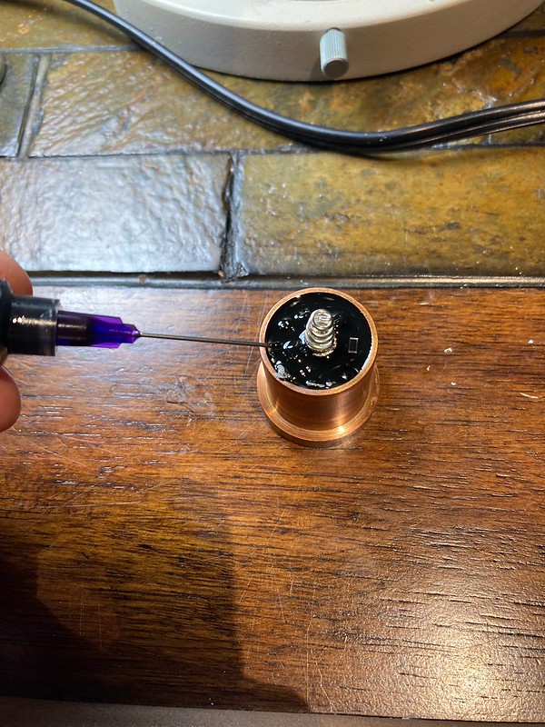
Potting using MG Chemicals 832HD. It isn’t the most thermally conductive, but has relatively low mixed viscosity and is inexpensive and easy to work with. I’ve been using the same tube for years and done a number of lights, all turning out good, never any issues with it not curing. I wait 24 h at room temp to cure.
First I put a bead along the edge of the driver, and a drop in any holes in the board, and let it cure. Then the rest of the driver can be potted without worrying about it leaking through and getting on the LEDs.
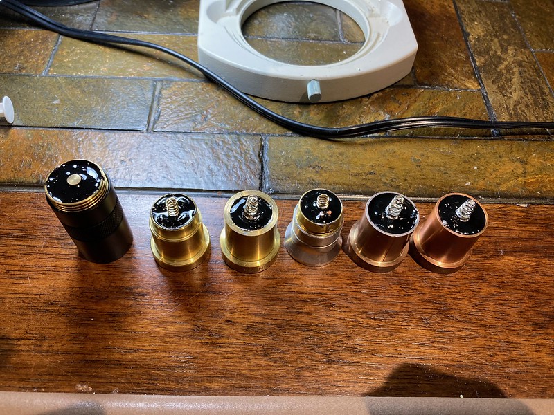
Potted some others at the same time.
I use a syringe and patience, lol. Even though it is “thin” compared to other MG Chemicals potting epoxies, it does take a while.
After curing:
1 (a few bubbles/dust particles)
2 (came out so shiny)
After the first side is cured, repeated like this for the second side. Unfortunately it is difficult to be sure what is going on since you can’t see inside. For the 20 mm Convoy boost drivers, the max component height is ~3 mm, so a disc of those dimensions would be ~1 mL in volume. However, most of that is occupied by components, so I figured that 0.5 mL is more than enough. Sometimes you can also tell the height of the potting when the needle is removed, by how far it goes up (like an oil dipstick). There is always some uncertainty though.
Finally, marking the input voltage and firmware so they are easily known. Both drop-ins were done the same, below are two images of drop-in #2.
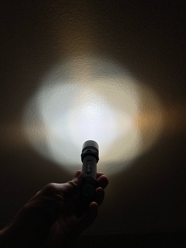
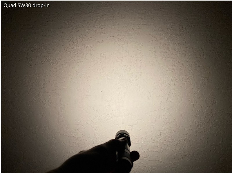
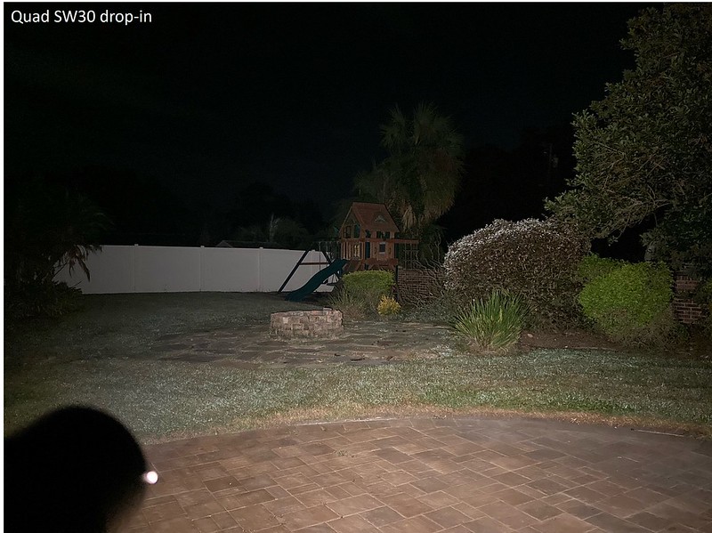
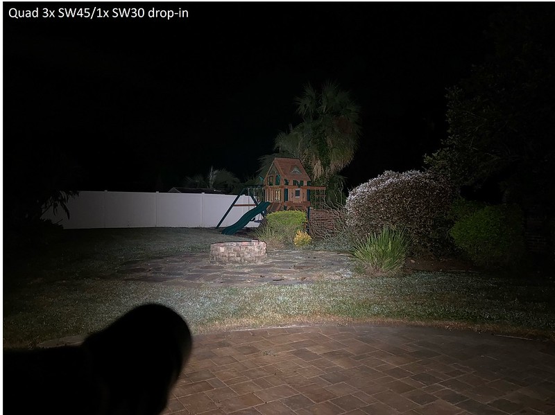
All the photos below are on highest output, with an SC64LE for reference. The quad SW30 has a floody optic, while the SW30/SW45 has a narrow optic.
I think that I may need to choose one drop-in as the official entry, which would be the second one I made, with the 4500K/3000K mix. The potting looks nicer and I like the four notches for optic removal.
Thanks to Hoop for all your hard work organizing, BLF in general, and the sponsors. I learned a lot during this project and tried to do things I wouldn’t have otherwise. Congrats to all other participants as well, for finishing your builds, and even just having an idea and starting it. Every thread was unique and I’ve enjoyed them all.