The backside is flat. They have graphs and charts showing same or better performance as compared to their version 1.
Efest IMR10440’s will allow 3A, that’s a pretty hot little XP-G2! ![]() Not bad on an XM-L2 either, even if it won’t last more than 5-7 minutes trying to power one.
Not bad on an XM-L2 either, even if it won’t last more than 5-7 minutes trying to power one.
RBD built me a AAA MiniMag that uses one cell, TexasPyro measured it with 261 lumens out the front. It’s hardly 3” long. Running an XP-G2 R5 2B on a SinkPAD that I turned down to 11mm
Edit: Scott totally reconfigured a 105c to fit this light, and it’s pushing 1.1A.
Aother type 14500 type mod not to be over looked is an XPE2. These can be driven up to 1.6A on a sinkpad.
I must be getting old then being so conservative ;-) Ok, I wouldn't know where to stash 5-6 7135's, but please make it a 2amp board then :love:
10XPG & 10XML please.
Shoot for 1.5A, if it only delivers 1A we’ll still be good! ![]()
And that’s a good point Vesture, stepping up into the 14500 class opens all kinds of doors…
I’d go in for 10 of each.
Also what is a Gerber file?
Software version of file that has the layer masks, and dielectric layers as well as the silk screen layers if used. It’s the file that SinkPAD uses to create the pcb.
i wouldn’t mind two of each, but shipping to Canada may cost more then the pads?
I would not mind a regular envelope with the pads surrounded on both sides by stiff card
Put me down as potential customer until shipping cost is finalized
Put me down for 10 xp.
I guess we should remind him to add HST also. :bigsmile:
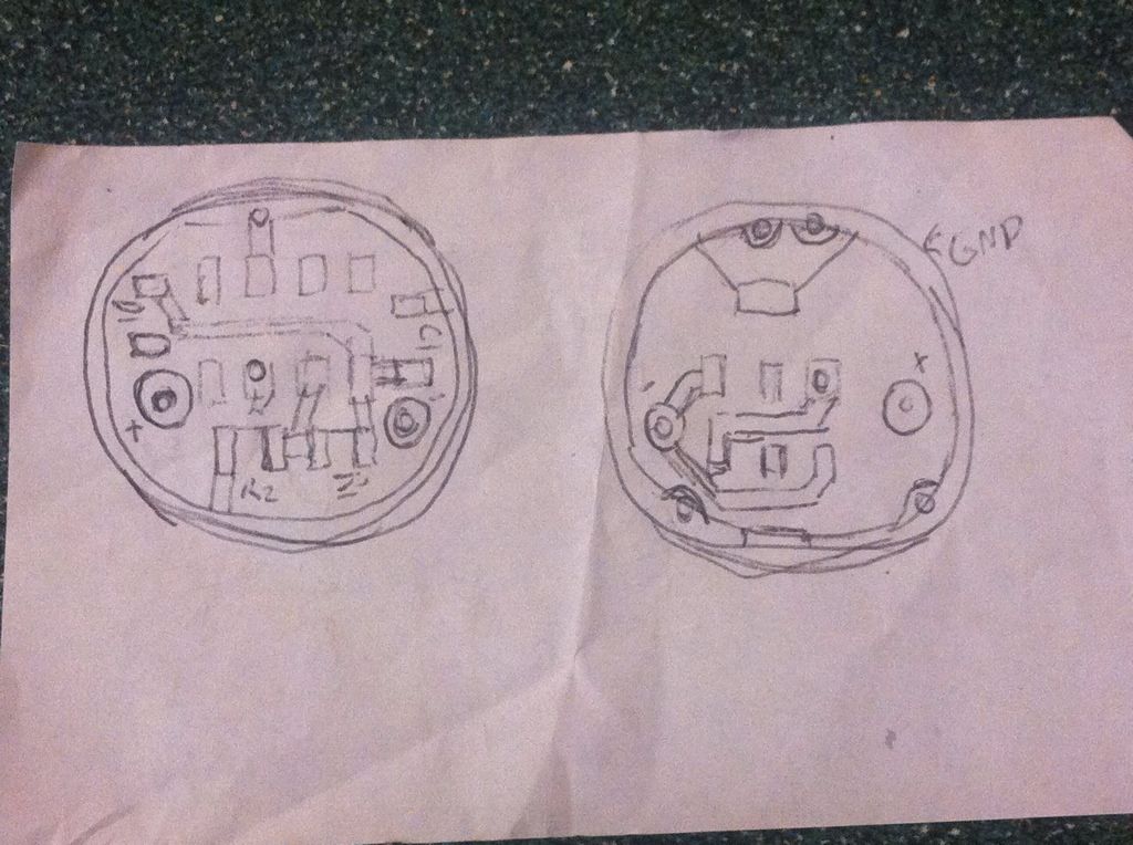
What I’d like to see is a driver board with a single 7135 footprint on one side with a ground ring and + solder pad(small) and all the other 105C components and led+,- on the top. I did a sketch and will post it tonight. Can’t do Gerber myself. ![]()
Edit - like this.
Anyone care to take a stab at it?
May as well put me down for (10) pieces, I’d definitely use them.
I would take 10 of each as long as the copper trace from the wire solder pad to LED+/- is little wider allowing to lower the resistance.
Eschewing the conventional battery contact spring I see, wiring it up …how?
A la one of OL’s solitaire mods with a wire to a separate positive contact. This would make it possible to use a linear driver with modes and low voltage warning in AAA/10440 lights. I’ve done 2 AAA Minimag mods where I cut up and reconfigured a driver to fit but it would be so much nicer to have a board that already fits.
I’ll take at least 5 of each…
Custom components for the DIY’r. High tech for the saavy! Confusing for me n Steve! lol
I’m really liking the idea of these boards, make it really easy to ugrade some emitters that I’ve been wanting to do, just been too lazy to cut down the stars I’ve got.
Hi Bluecvbc,
If I am not mistaken that trace between the LED + and - pads and where the wire solder pads are is basically only a bleeder for the solder. The underlying trace that the current flows through ( at least on my 16mm version) is the full width of the LED solder pads.
the bleeder is just not covered by mask as it’s all so close together. So the width of the pad, and then a little, should be how wide the trace under the mask is going to the emitter. No question that plenty of connective power is in place.
I got some Kapton masks from texaspyro that make reflowing a breeze! The perfect amount of solder, every time, such that there’s almost nothing coming out into the bleed area. Loving it! ![]() From XP to MT footprint, working like a charm! Thanks tp!
From XP to MT footprint, working like a charm! Thanks tp!