Yes sorry I should have detailed more.
Cathode is the LED - (anode is +).
HDR stands for high dynamic range dimming. If you have a driver with one power channel like a linear or buck/boost driver you are limited by the resolution of the PWM, so 8bit or 10bit (higher then becomes limited by the precision of the current sensing circuit) but that’s still not enough for moonlight modes, a 5A driver with 10bit PWM can only be dimmed to ~5mA which is arround 1.5lumen.
To get a much higher resolution I use (like Zebralight, Armytek, Loneoceans, Mike C) multiple sense resistors, 2 in my case (ZL use 3 in most of their drivers), which are selected with a mosfet (which I call HDR FET), here is the shematic of the linear CC circuit :

(R9 should be 10Ω here, not 5. R11, R10, D2, C6 are for the hardware delay)
To quickly go over how the constant current regulation works : In this configuration the op amp will increase or decrease the gate voltage of Q1 (acting as a variable resistor) so that the voltage at the inputs of the op-amp, Vset and Vsense, are equal. In order to get the desired current we apply whatever voltage gives us the desired voltage drop across Rsense. If we choose 50mV Vset, we get 50mV Vsense, with Rsense = 10mΩ that means 5A. Basically this is a voltage to current circuit.
But Anduril only outputs a PWM signal, the attiny1 series do have a DAC (8bit) for outputing an analog voltage but there is no support for it in Anduril, so we convert that PWM signal into a voltage with an RC filter. The downsides are that it doesn’t smooth it completely (ripple), but with a C value high enough it’s good enough, and it takes some time for the voltage to rise/fall :
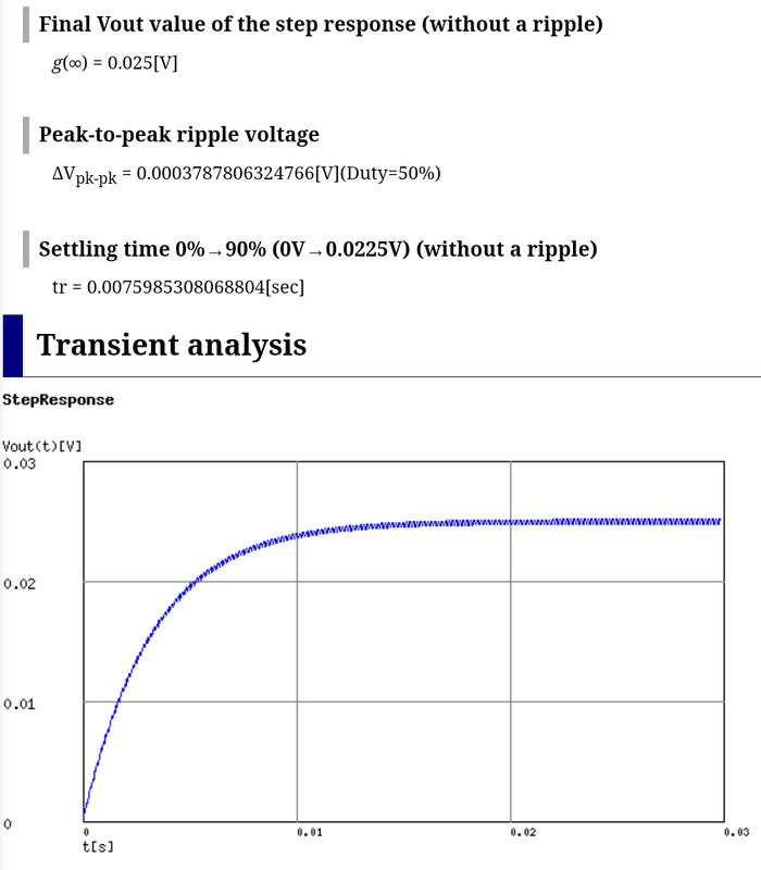
This is with the values in the shematic, with a PWM freq of 10kHz, duty cycle of 50% and a PWM voltage high of 50mV, it takes about 15~20ms to reach the desired voltage (25mV), and consequently the desired current.
Getting back to the HDR function, when the HDR FET (Q2) is ON the sense resistor is Q2(~2mΩ)+R8 = 10mΩ (there is R9 in parallel but it’s too high to matter), with Vset = 50mV current = 5A. At PWM 1/1023 we get ~5mA (just dividing by 1000 to simplify).
When the HDR FET is OFF the sense resistor becomes R9, the current at 1023/1023 becomes 5mA, and at the lowest level 5μA ~ 0.0015lm.
Effectively we get 20bit dimming with 10bit PWM. Though in some cases when Vsense is too low the output can be unstable, so we might not use the PWM level 1 or 2, decreasing the total resolution, but there is still plenty enough.
For reference the SC/H600 mkII have the lowest level at 100μA.
In CFG the ramp looks like this (only 30 steps to not break the page) :
With this :
(*)
We ramp up and reach ramp level 10, PWM 1023/1023 Vset/Vsense = 50mV, current =5mA because HDR FET is OFF, Rsense=10Ω, then it reaches ramp level 11, HDR FET turns ON, Rsense is now 10mΩ, due to the RC filter Vset is still at 50mV (5A) and fall to 50uV (50mV/1023) over the course of 15~20ms : that’s the flash.
So we can either add a delay on the HDR FET so that it takes >20ms to turn ON (that’s what I’ve done in hardware, but software would be miles better), or like you suggested use the middle ramp blink to turn the LED OFF during the Vset settle duration.
(*) Typing this I just realised that PWM level 0 in the blink function will actually turn off the op-amp/linear FET (Q1), contrary to what I said in the comment above, I’m stupid…
I’ll test that, I do worry that the op-amp doesn’t turn off instantly.