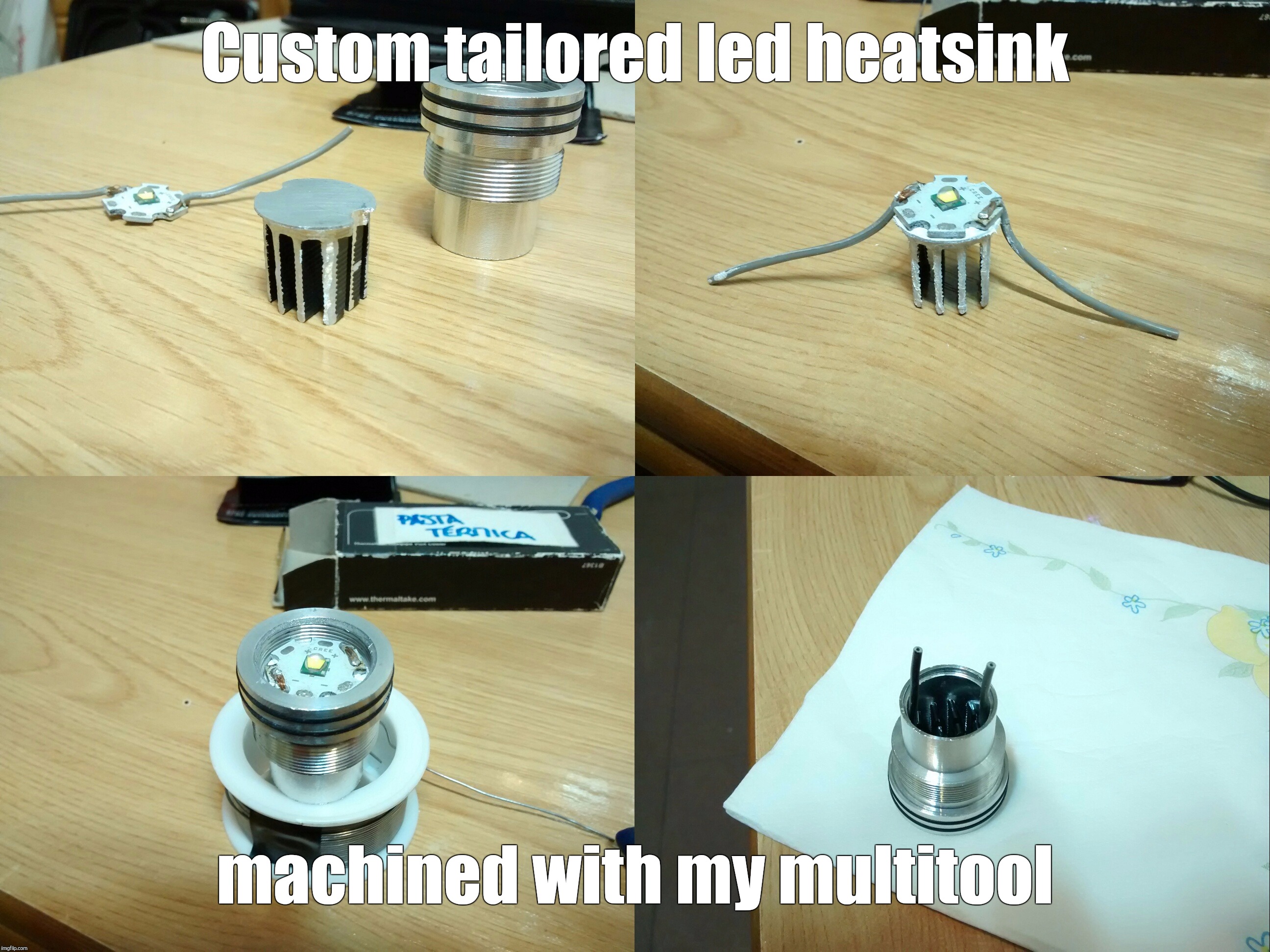
Well, I’ve recently stripped a suckass zoomie torch I had lying around. I am machining a small heatsink to fit on the underside of its led along the hollow pill’s tube.
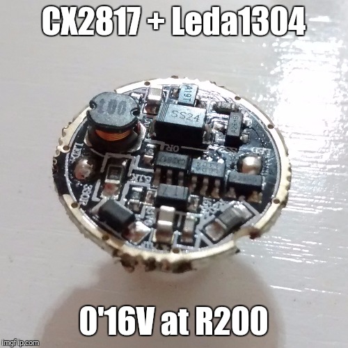
The torch uses this driver:
Buck driver which could make use of a pair of in series (protected) cells.
Since it uses a current sensing resistor, I’ve figured out I could increase the driving current by reducing the value of this component. For example, I could solder another 0’1Ω resistor in parallel with that one to attain 2’4A of current (I = 0’16V / (1/15)Ω). No small resistors I have available; gonna make ’em of thin long wires. :person_facepalming:
However, I am wondering if that would be wise. I do not really know how far could I push the board’s components and what are the main limiting factors.
Any help is appreciated.
100% freehand made. :sunglasses:
Regarding the driver question, I have some AWG28 copper wire composed of a pack of 9 “hairs” which, according to my data, should have about 0’15Ω per 27” (685’8mm) of lenght. That means I’d just need 3” of one of those hairs to raise the driving current to about 1’866͡A, yet I don’t know if that is enough copper stuff to dissipate 0’18W in heat without overheating.
Any willing to help soul reading this? :question:
Well. Your ways are a little unorthodox, but who’s aren’t, right?
If you use copper wire, there will be plenty of copper to dissipate the heat you will get. I have no idea how the rest of the driver will respond, but if it were mine I wouldn’t hesitate to give it a try. But I wouldn’t mess with the wire. Where would you put it all? Do you have any old electronics laying around that you could open up to try and find a resistor? This is what I usually do. For high current resistors like these, I can usually find the one I need from the circuit board of old laptop batteries. I’m not sure what you have laying around l, but you might find something?
I don’t know a heck of a lot about buck drivers but the inductor might saturate with the added current, the ss24 diode might fry above 2A, and the buck IC might need additional heat sinking to survive.
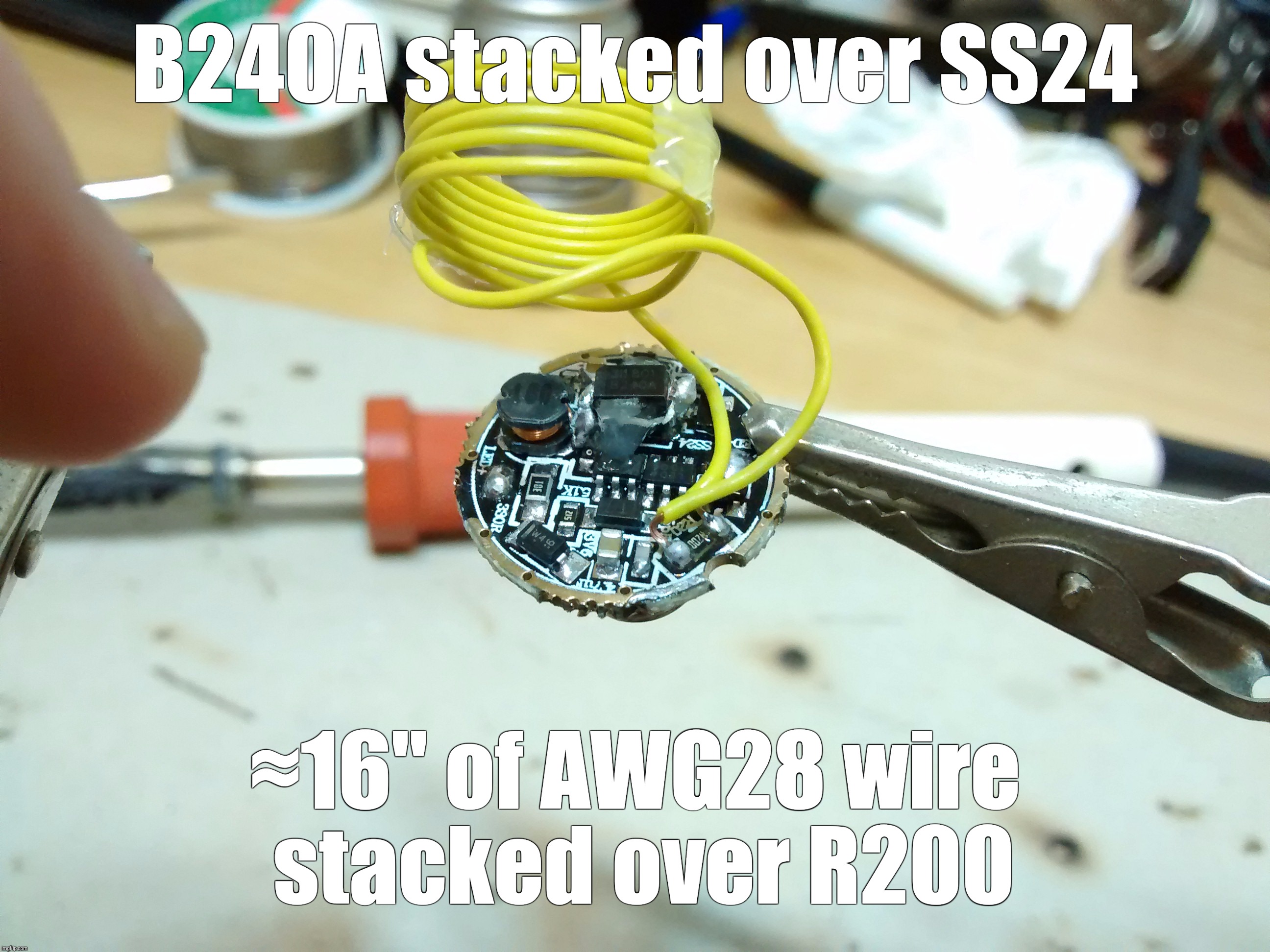
Well, no small enough resistor found among a good deal of my electronic wreckages; however, I’ve found a B240A schotty, which seems to be an SS24 equivalent from a different manufacturer.
I’m planning on stacking the B240A over the SS24 with thermal paste in between (thermal coupling) and, thus, dare to increase the driving current a bit more. For 2’6A, 16” of AWG28 would do, and I’m pretty confident I can stick all that wire inside what you can see in the above picture(s). Heck yeah!
More on this later, I have to deal with soldering that tiny stuff with my 3×1’5mm soldering iron’s tip. LOL!
That 0R resister is probably just for switching between 5 modes and 3 modes (High, Low, Strobe). Supposedly the 0R resisters are not actually totally zero ohms. You could use it if you want to get close to totally bypassing the voltage sense resistor. Wish I had some answers to your questions, but my electronics knowledge is not very deep. For sure I would recommend getting yourself a few choice sub-one ohm resistors to that you can step down resistance in steps. I like to use two wires so that I can swap resistors without having repeatedly torture the driver.
Since it was designed for up to 2S li-ion input, I attached a 2A 5V power supply to it.
After some tinkering it powered up, high pitched humming noise, brightness was low. I remember it was supposed to start on high but couldn’t remember if it had next mode memory and, with all the previous ON/OFF tinkering I certainly didn’t knew in what mode it was so, I switched modes into strobe… BRIGHT YEAH!
I wielded my IR gun to take some measurements over the led but, after a few seconds… magical smoke came out. Game Over! :person_facepalming:
Winding that wire like that may have created an inductor. If so, it would have asorbed voltage like a battery and gave your buck converter (chip marked LEDA xxxx) a false impression what was happening in your real inductor. That could have caused your buck to not regulate voltage properly.
The way a buck works is that the inductor absorbs the excess voltage that the LED does not use. A magnetic field builds that holds the stored voltage. When it starts getting full, the voltage to the voltage sense resistor raises to a point that the buck convert then cuts power from the battery. The stored energy in the inductor is then unleashed and powers the LED. Voltage to the voltage sense resistor drops and the buck converter reconnects the battery again. The cycle is continuous.
Can you tell which component failed? If your lucky, it will just be a resistor. You will usually see a black spot in the center of the resistor when that happens.
Well, I had to twist and shape a bit that inshuntor, shuntductor, etc for it to fit into the now crowded space behind that massive sinkpill, though I get your point.
A short while ago I desoldered the driver from the led and, taking a peek over it, I sort of saw something strange on that 10KΩ resistor at 1 o’clock from the inductor: my multimeter showed continuity over its leads. So far, so good. :confounded:
Depending on the circuit, you could get a continuity reading even without a resister on the pads. I would say the most likely think that failed is the Buck Converter. I keep a batch of those on hand as they fail pretty easily when modding drivers. They seem reliable though in operation. That Buck Converter you have there seems to be the most common one used in budget buck drivers.
You said there was some smoke though. I haven’t had any smoke from a buck converter failure. Generally, smoke means a resistor failed, atleast for me so far. Doesn’t mean the buck converter didn’t also fail.
So you’re looking for a 20mm buck driver. Hopefully, someone chimes in with a good one. If you search CX2817, you may find some mods were folks have replaced their CX2817 driver with better driver.
I understand measuring the resistance between the leads of a laid out resistor isn't likely to give all of its value (other paths'…), but short-circuit?
Well, did some tidiness treatment on the board: desoldered the B240A (missed a broken leg), the shuntductor, changed a 300Ω resistor I broke in the process and cleaned up/redid some stuffed joints, 10KΩ resistor ones included (and it seemed fine after that). The inductor splitted above its base, but no critical harm was apparent.
After going mad for a while because don't know where the fuck did I laid the PSU connector adaptor I was using tonight, I laid down for a nap. Tested it again a while ago, to no avail: obviously, since I hadn't replaced the firecrackers… LOL!
As you said, it most likely is that buck IC (LEDA 1304?) or I don't know what the fuck. Period.
^
LOL, I hear you bro. I have a bunch of “case closed” drivers myself. This can definitely be a frustrating hobby at times. At least, you are able to keep a sense of humor about it all.