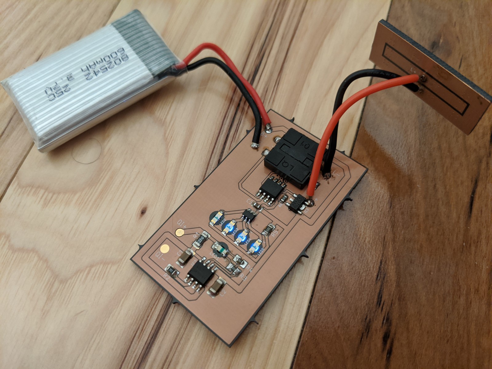
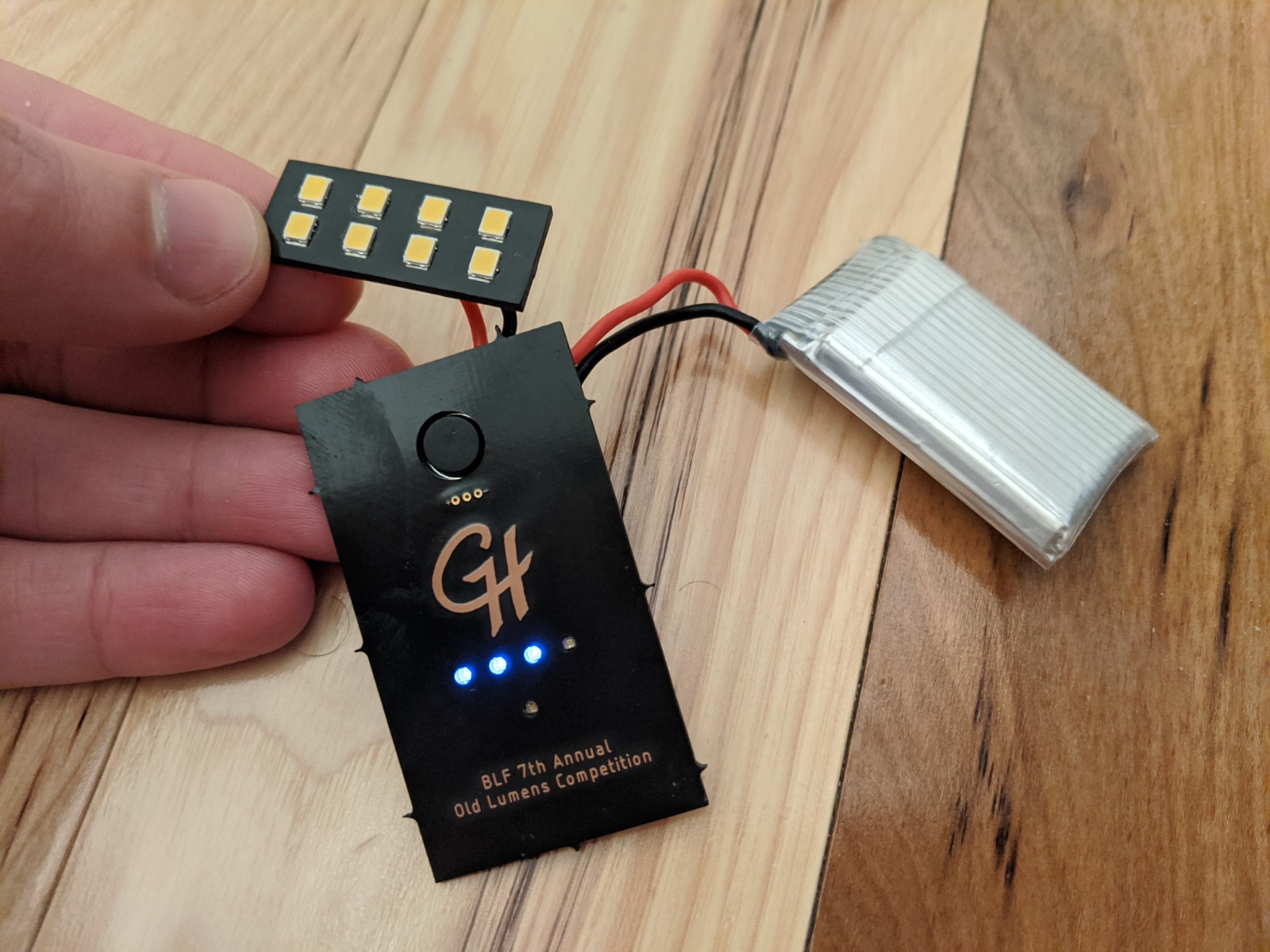
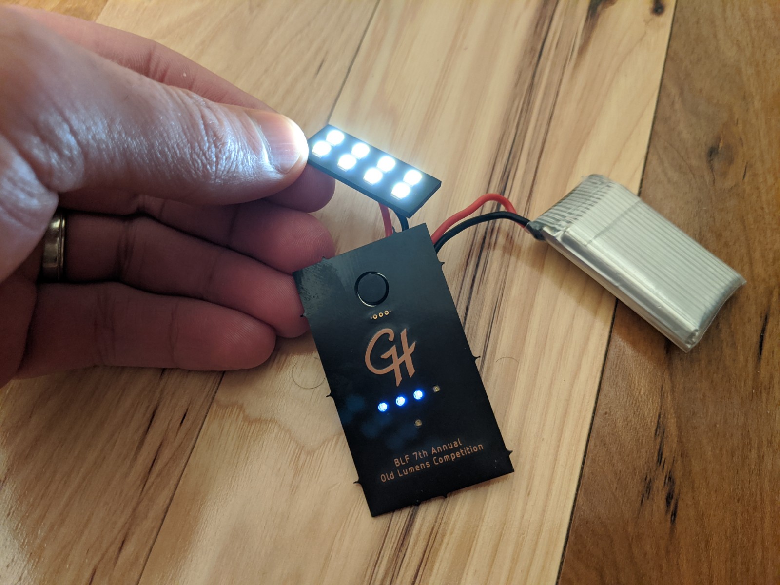
Most of the electronics have been assembled and tested for functionality. The main PCB has been assembled, along with the LEDs on their PCB. Sidenote, but the 4000K looks really good; I’m glad I went with those. I soldered the battery on (at least temporarily). The piece I haven’t soldered on yet is the Qi charging coil, thus the charging circuit hasn’t been tested yet either. Perhaps tonight.
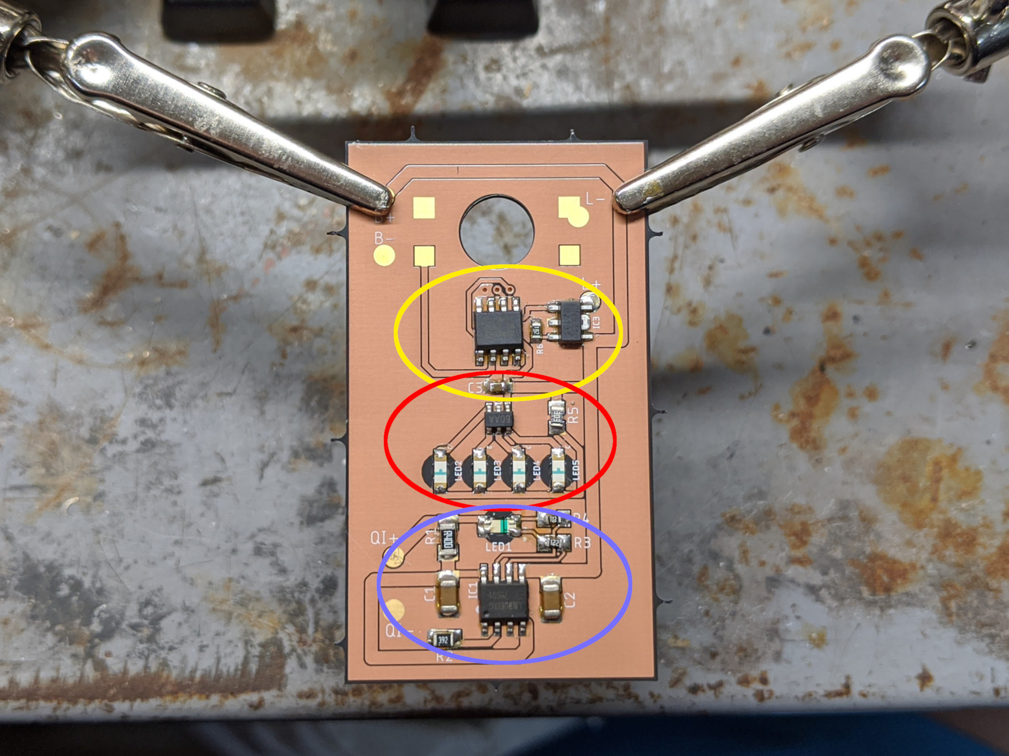
Here’s a breakdown of the circuitry (encircled in the image below):
- Charging circuit in blue: these parts were scavenged off of a standard TP4056 Micro USB charging module. The modifications here are (1) the input will come from the Qi receiver instead of the USB port, (2) the current set resistor was swapped so that the charge current will only be 300mA instead of 1A, and (3) the indicator LEDs were replaced with a single reverse-mount red/blue LED.
- Battery indicator circuit in red: this is the same HM1160 circuit used in my recent LED tailcaps. This is a really easy-to-use IC with minimal part count. I used blue reverse-mount LEDs for this.
- Main control circuit in yellow: the brains are an ATtiny412 running RampingIOS (D4 V2 UI) which are controlling a CN5710 which is set for 1 amp. The UI is currently stock, but now that I know that everything is working fine, I’ll be doing some customizations like re-arranging the multi-click options and implementing a “hold for low while in lockout” feature using the exposed programming pads.
Next up: (1) test the Qi charging circuit, (2) form the brass casing