A Lumen Tube you can build that reads out in Lumens without needing adjustment tables.
“If you can’t make it Perfect – at least make it Adjustable” Said a wise man.
[EDIT – 8-20-21]
Part 2 – The Build and Tuning has been added to the next post below.
Some corrections / additions have been made to part one.
Addition to Part One
After fussing with this thing for some time now, I’ve believe I have some design philosophy that needs to be added.
The Spot-Flood Conundrum
One of the most vexing things about these designs is the difficulty of dealing with beam patterns. Seems if you get it calibrated for a flood pattern – it will be off for a tight beam.
This drove me nuts in the initial design where I was trying to duplicate the more compact versions using three 90 degree bend pipe sections.
I believe the solution lies in…
What Happens in the Tube -
Needs to Stay in the Tube
Take a look at these two pics.
Zoomy Pics

Both are a zoomy. See how much light is hitting and escaping with the flood pattern? You can see where the spill hits the side tube about 1/3 of the way down from the top.
Zoomed out the spill misses the pipe. Still the reflected and diffused light is lighting up the pipe.
Lining the Tube with reflective tape keeps all those photons inside (well most anyway).
In addition, the flashlight head must be mounted so that any light reflected back toward the top of the Tube is directed back into the Tube. Thus the cardboard rings fitted to each flashlight head and coated on the bottom with silver tape.
This makes a significant difference in the Lumen reading.
The elbow section, while made of thicker plastic, also absorbs/transmits light. This photo of a brighter flashlight illustrates that.
Elbow Pic 1

I tried different solutions.
Elbow Pic 2

The results were a bit of a surprise. Using the same light.
The naked elbow read: 157Lm
An elbow coated on the exterior with “chrome” paint: 154Lm
An elbow coated inside and out with “chrome” paint: 105Lm
The elbow with the exterior covered in aluminum foil: 165Lm
The “chrome” paint is more of a sliver. I tried two different spray cans and they both looked about the same.
Foil is the way to go thinks I.
What happens outside the Tube -
Needs to stay outside the Tube
The converse to the above is also true. Exposed PVC pipe sections allow exterior lighting conditions to influence the readings. Unless you are going to always make measurements in a darkened environment.
The Tube assembly needs to be insulated in something to prevent light pollution.
I found this particularly important where the lux meter attaches to the 3-2 reducer. Any additional exterior light in this area knocks the low Lumen readings off. A wrap of Aluminum foil does the trick.
Diffusion to the Max
The second part of solving the spot/flood conundrum is making sure that the light is fully diffused by the time it gets to 90 degree elbow. This prevents a spot beam from reflecting differently from a flood beam.
This, I think, is the problem with many of the twisty Lumen Tubes. It’s not that they don’t work or can’t be calibrated.
I just think it’s harder to calibrate if a not completely diffused beam is bouncing around inside the pipes. The bends are used to diffuse the beam, but the spot/flood reacts differently in the first bends (or so I surmise).
Take a look at the pic below.
How well does the Translum Film work?
Laser Pics


This image is taken at the bottom of the coupler that sits on top of the Light Valve.
That even green glow looks pretty consistent. The source is a laser. About as close to a point source as you can get. The ultimate tight beam. It is further diffused by additional film below the Light Valve.
My design has the beam very well diffused before it hits the elbow.
As long as the majority of the light makes out of the defused Tube area, I think most of the differences in beam patterns are minimized.
Taking this a step farther – I think a Lumen Tube that has no bends in it is the optimum design.
The straight sections can all be lined with reflective material and there will be no bends to react with different beam patterns.
If I decide to try to make a 6” version – It will be a straight Tube all the way.
[End Edit]
This is a work in progress. I was cruising along on the project pretty well till the bug hit.
I put this on hold while I social distanced, made masks, and started hording TP.
I’ve got that covered now and wanted to start my Lumen Tube project again.
I’m starting to have a few health issues and may not get it finished to my satisfaction in a timely fashion.
So - I decided to get this out so others could take a look at it. And I’ll keep moving toward the finished version as I can.
All the images link to a higher res if you want a closer look.
DYI Tube in progress pic.
I’ve been using a home built light box to measure lumens based on a Styrofoam cooler (a Lum-a-box? Igloo-a-Lum?).
I use filters inside the box so that it reads out in Lumens on the Lux meter. It works OK for floods but it’s way off for throwers.
I could adjust the filters to make it work for different conditions, but that required opening up the box and messing with stuff.
A total pain in the butt and hard to reset after fussing with the darned thing.
I ruminated (always wanted to use that word) that a setup could be built that could read out in Lumens and be able to adjusted to correct for differences in - well - all the stuff that makes getting a good reading so hard to do.
I didn’t want to have to use any correction factors.
I also didn’t want to have to spend two lifetimes making little adjustments to make that happen.
Ergo - The Tube had to have external adjustment.
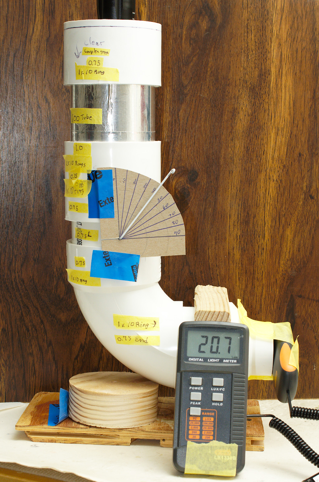
My solution is the Light Valve. A section of pipe that can change the amount of light that passes through it. Shown here in prototype.

High or Low K lights throw off the reading? – adjust the Tube.
Correct for differences in Lux meters? – adjust the Tube.
Phases of the moon throwing the readings off – adjust the Tube.
Want higher results so makers will send you more lights? – Adjust the… You get the idea…

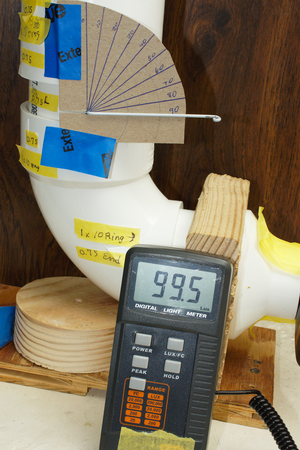
As you see with the valve in this configuration, I can vary the output by about 20%.
Having watched other builds and most importantly the awesome work done by Texas Ace I decided I’d give it a go.
From TAs thread I perceive there were 3 main issues he had while making his tubes.
- The diffusion material was not consistent.
- Small changes to the tube assembly (how the Pipes/Diffusers Fit) would make changes to the readings.
- Each tube had to be carefully calibrated by hand – perhaps the biggest hurdle of all.
TA said it took literally 6 months of tinkering to get things sorted out. I believe him!
And TA, please feel free to correct anything I say regarding your epic build.
I set out to see if I could come up with a way to perhaps circumvent these issues.
Hopefully creating a design that any who wanted to could give it a shot could and build their own version.
So here it is so far.

If you want to skip the R&D part (and my long ramblings) and get to the end result, jump down to the next POST marked “DYI Build”.
There might be some useful build tidbits among all my ramblings….
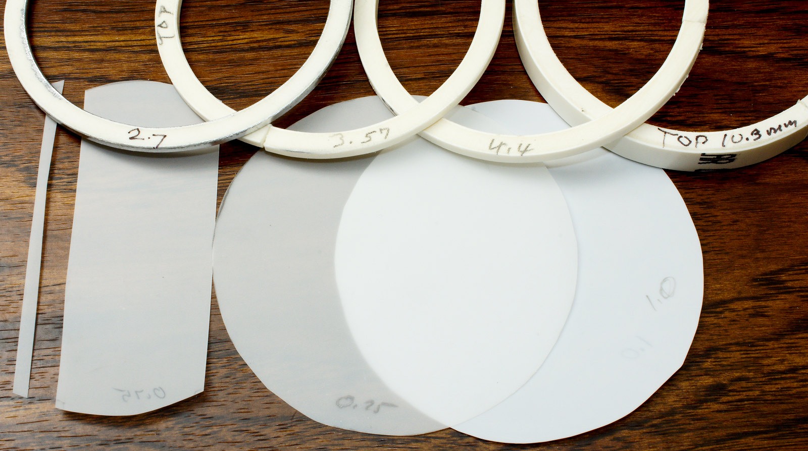
Diffusion Confusion
The first issue was finding a diffusion material. Instead of the hardware store I turned to the photographic world.
I looked at various options (BHPhotovideo has lots of choices) and settled on something called Translum.

This is a diffusion film meant to be used over photo lights.
It is a thin plastic film. It comes in 3 strengths 0.75, 1.0, and 1.5 stops with correspondingly more diffusion for each one. Each also reduces the light transmission by the listed F-Stop (my grasp of the obvious is overwhelming).
I bought a trial pack that had 2 sheets of each in it ($30).
Disks Video

Since it’s designed for Photo LEDs it should stand up to heat well. Being a photo product it is consistent across each sheet and from sheet to sheet.
The thin plastic film is sturdy enough to not warp under its own weight (at least in the 3” tubes). It is easy to cut with scissors.
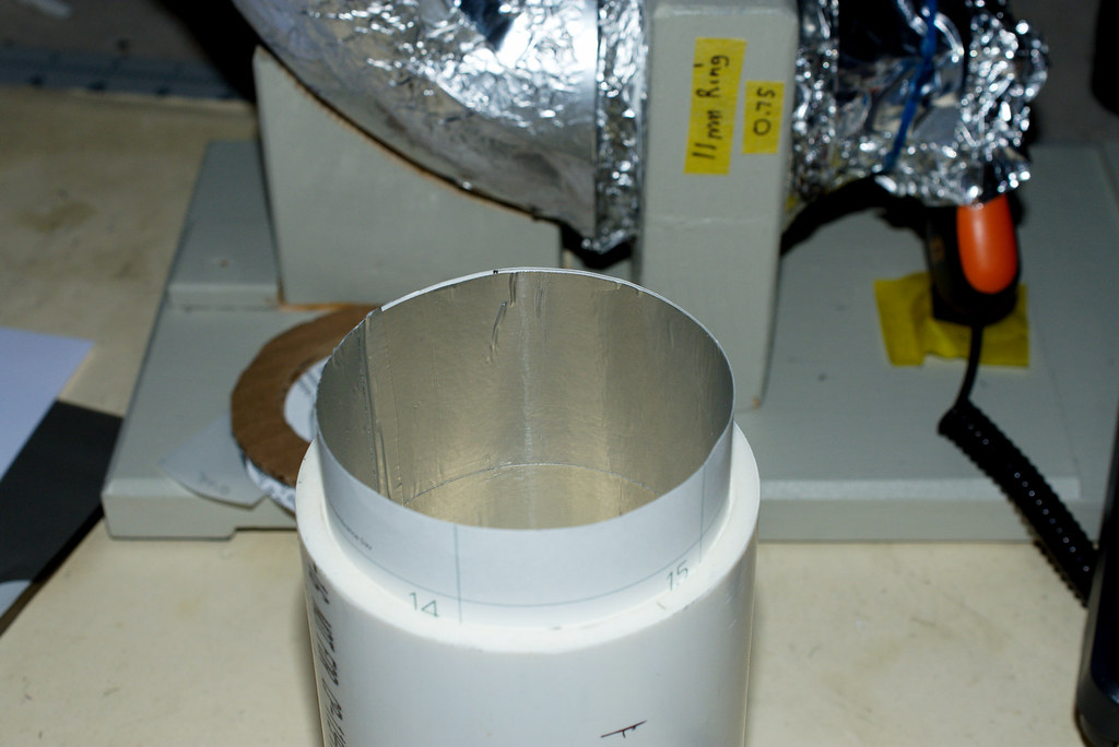
Pipe Dreams
Next I turned to the tubes. I went to Home Depot (or Lowes) and picked up some 90 degree street elbows. These have a female on one side and a male on the other.

The brand of the fittings (at least the 90 degree thingy and the pipe) is Charlotte. Here’s a shot of the brand.

In addition I got a few in line couplers, a 3” to 2” reducer, and a short length of precut 3” pipe. All series 80.
I chose the 3” size because the fittings are MUCH cheaper than the 6” versions.
If it Fits well, Well it won’t – Fit well that is
Test fitting the pieces together is problematic if you expect to get any consistency. Some joints push up nearly flush while others require substantial force to get them close to seating.
 ,
,
Getting the tight joints apart is a royal pain. The parts need to come apart and be reassembled with consistency during the design and tuning phase. Even a 2mm difference in joint fit will change the measurement. And you will be shuffling parts around a lot.
Ring and Diffusion Video

Lord of the Rings
The joints need to be tight enough to stick, yet loose enough to make changes.
My solution was to make a guesstimate on how much space to leave between each joint. I then cut ring spacers from the pipe. I settled on a 1cm (10mm) thickness. Your mileage may vary depending on your parts.
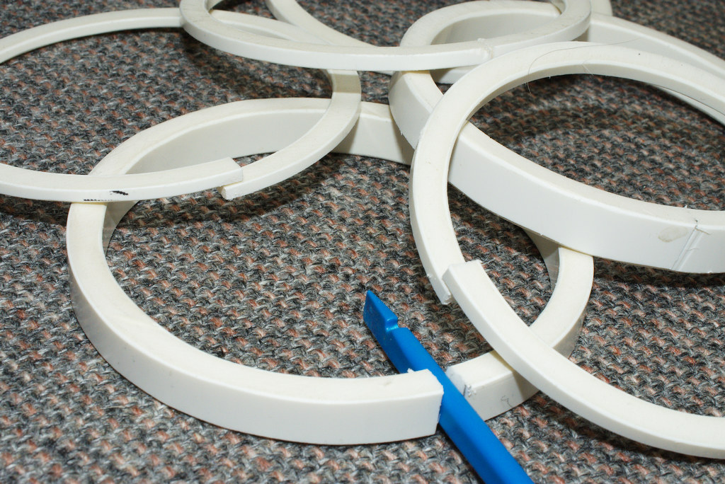
The spacers and rings won’t fit all the way into the joint, so I made cut in the ring and opened it up until I got a good friction fit. These rings keep the joint fit consistent.
These rings also act as retainers for the diffusion film disks.
I found I wanted to hold film (in some instances) against the spacer rings. I cut some additional rings about 2mm thick and split them also. These are used to keep the film in place as needed.
These rings are also used as spacers in fine tuning the Tube.
Marking the cut is as easy as getting something the desired ring thickness and setting the pipe on end. Then spin it against the marker with a pencil on top to make a line around the pipe.
I used a band saw to section the pipe, but a scroll saw or fine tooth hand saw would work as well.

After cutting the pipe it needs to be de-burred by sanding the cut lines on the inside and out. It also helps if you taper the outer edge ever so slightly.
I used a cheapo Harbor Freight belt sander to smooth out the cooties left by the saw blades. Hand sanding or a file works too.

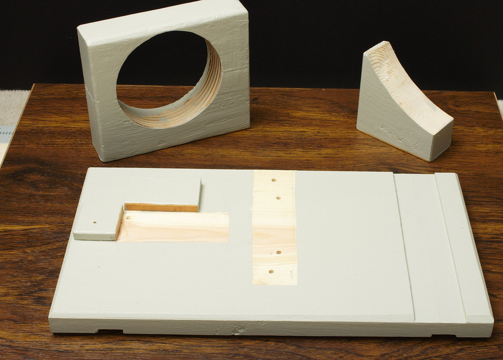
Flashlight Support
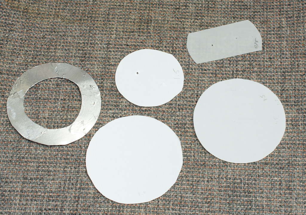
I cut a disk from 1/16” clear plastic to act as a support for the lights. This was just some scrap I had laying around. Anything strong enough to support the flashlight will do.
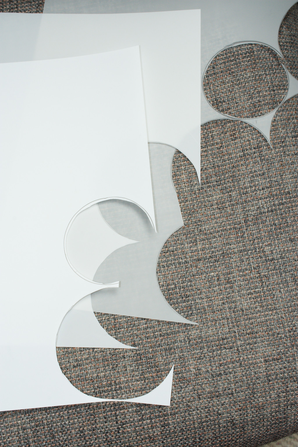
Use the rings mentioned above as templates for cutting the Translum and anything you want to fit inside a coupling or inside a pipe.
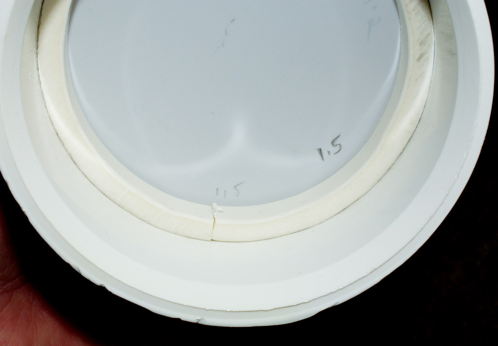
I used heavy paper to make the doughnuts that act as baffles to fill the space between the flashlight head and the Tube diameter. You will need one for each head size.
I coated the bottom of the doughnut with shiny metal tape.
Thin cardboard would work better as it keeps the light from moving about.
The Doctor is In
 ,
, 
The meter is the ubiquitous Dr. Meter available on Amazon (about $45) and elsewhere. It fits nicely in the end of the 3”–2” reducer. I already had one on hand.
Interestingly the sensor of the Dr, Meter uses the same Osram photodiode that Terry Oregon and I tested for PWM measurements.
The diffusion film does a really good job of dispersing the beam.
Here is a shot of a zoomie through 1 layer. And again after a 10cm tube and a second layer of film.
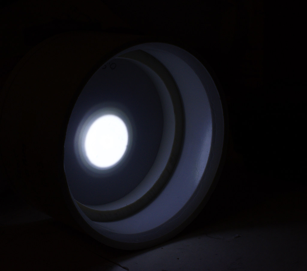 ,
,
The film works so well that multiple 90 degree turns in the Tube are not needed.
I wanted some space between layers so I chose a 10cm tube between the top layer and the next.
This will change in the final DYI design. Start with a longer tube and shorten it to tune the system.
Tube Lining
When looking at the Tube with a flashlight shining, I could see light passing through the straight pipe walls. I want to keep as much light inside the Tube as possible. Also I wanted to keep external light out of the system.
I took some heavy paper that is a little heavier than Nat. Geo. cover stock. (But thinner than Index card stock).
I cut rectangles that just fit inside the straight pipe. I covered one side with metal duct tape. Then I fitted it inside the pipe sections. Shiny side in. A little extra metal tape joins the ends together. It is just a slip fit.
You can see it here inside the Light Valve.
Valve Mounting Pic

Not much light was coming through the joint sections. It’s thicker and only a small part is exposed to the light.
I covered the outside center parts with the metal tape. Just to be sure.
The 90 degree elbow I covered on the outside with foil. I’ll try a more elegant solution later.
I also covered the outside of the reducer with metal tape. I left the inside alone. I think it would bounce some of the light back up the tube if treated with foil.
And yes, every little change made to the tubes makes a measurable difference in the readings.
Needing re-calibration each time. What a pain. I feel for you TA.
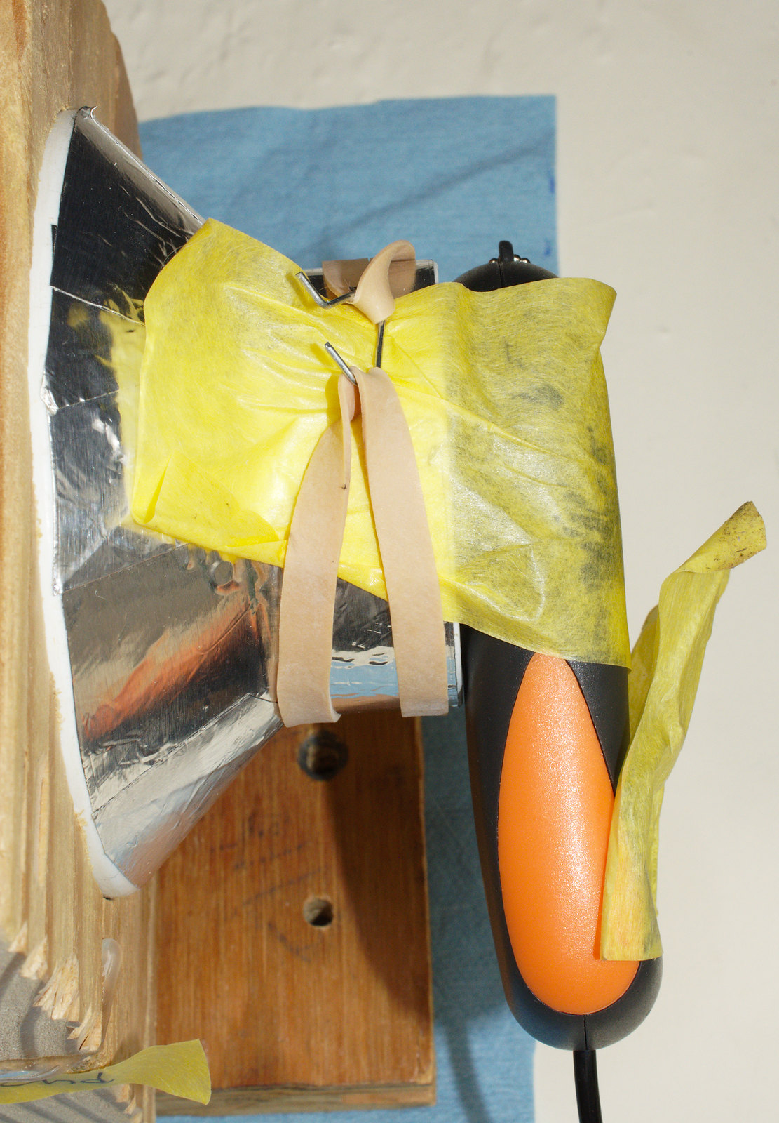
Mount The Tube
Using a single 90 elbow at the end made for easy mounting and parts swapping.
 ,
,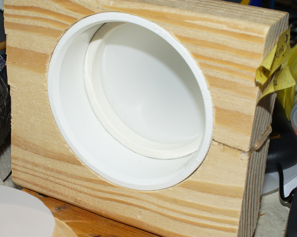
I cut a 4” hole in a hunk of 2x6 and stuck the reducer in that. I made a side cut and sqoosed the hole a little tighter using some hot glue (the DYI’ers best friend). It’s now a friction fit.
With the rest of the assembly vertical the joints need not be so tight to keep things together. That makes swapping out different pieces much easier. And you will be taking it apart often.

Trial and Error, and Error, and…
Now comes the fun(?) part. Slapping parts together and hopefully coming up with a combo that makes the LUX reading correlate to Lumens.
So after much (much) trial and error I came up with a design that was close to converting Lux to Lumens.
I filled many – many pages with failed attempts.

I don’t know about TAs adventures, but let me tell you when I finally started getting readings that were in the ballpark…
Well - The skies opened and the heavenly choir began to sing.
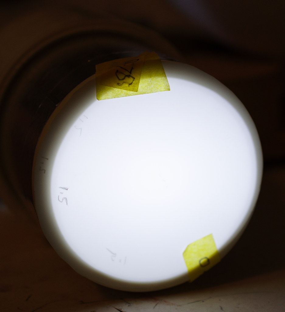
If you decide to build your own – Label everything – EVERYTHING!
Label Everything Pic

AND use something to record each change, no matter how small.
Ask me how I know. No don’t, it will take too long.
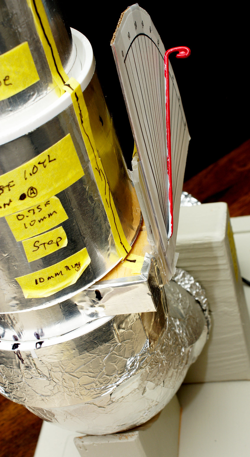
The Light Valve – Calabratable – Not Calibrated
The problem with Lumen Tubes is the final adjustment.
Let me tell you dialing in the last few percent is beyond a royal pain in the butt.
I didn’t want individual builders (or me) to spend way too much time adding or subtracting bits of film or be forced to use a correction factor.
The Light Valve
I was adjusting the tube by adding and subtracting filter sheets and parts of sheets.
Then I thought about a simple valve. It works for water and air, why not light?
I took a section of the straight pipe and drilled a hole suitable for poking a coat hanger through it.
By luck, I miss aligned each side just a bit. That made enough tension to hold the hanger without it moving.
I then added a disk of Translum to the inside of the pipe attached to the coat hanger/rod.
Scotch Magic tape – the frosty stuff works fine.

Shown is a 0.75 disk with a section of 1.0 material on top. Using mixed values you can adjust how much change the Light Valve makes to the readings.
I started with a 1.5 density and eventually got the rest of the tube close enough that a 0.75 disk would do.
Now I have a Tube that can be adjusted externally. I added a set of marking on a hunk of cardboard so I had a reference scale.

How repeatable is it?
Very. Using well regulated lights the reading is within a few Lumens (out of say 300lm) after moving the valve to other positions and bringing it back to the first setting.
A drop of hot glue (naturally) will fix the film to the rod after my experiments are complete.

By having an external adjustable Tube it is possible to dial in corrections for all the other variables.
All this, of course, is predicated on having lights of known values.
Another saga for another time.
So if you’ve lasted this long, and want to give it a try.
I’ll try to get the next section finished as quickly as I can.
See the Next POST For the Build.