Great build, Don. Can’t wait to see it finished. ![]()
Making great progress MtnDon! I like how the polished aluminum looks.
I’m looking forward to the final reveal too ![]()
Excellent work ![]()
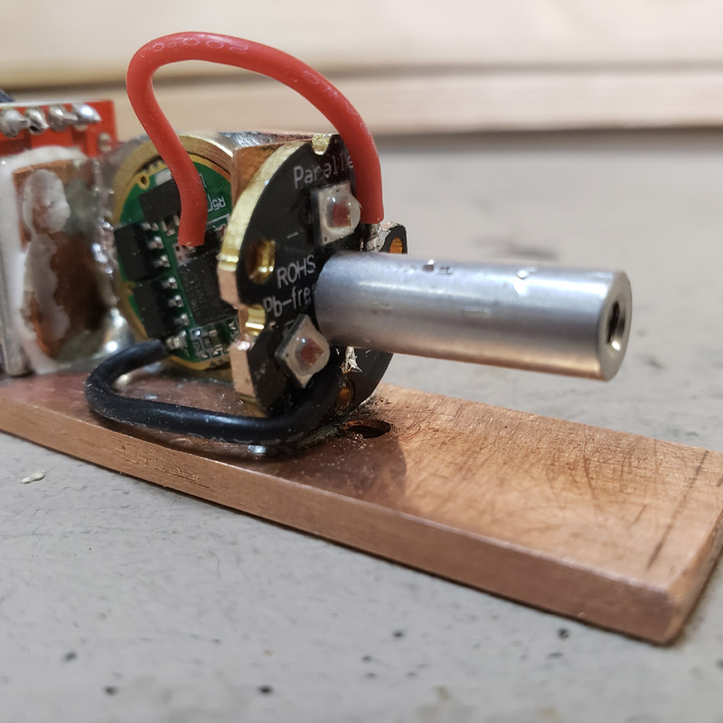
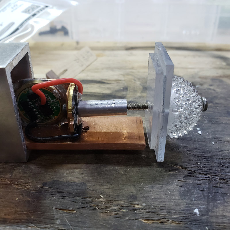
I flashed the Nanjg driver that will be powering the rear-facing LEDs. FWIW, here’s a little thing I put together some time ago. The cell, charger, switch and led stay in place and I can switch the driver for whatever one I am working on. It’s probably overkill but all the parts were on hand.

After flashing I installed that driver in the rear mount, using a couple of dabs of solder around the perimeter. The rear end is to the right in this shot. With all the copper sucking up the heat from the soldering iron I had to turn the temperature way up in order to get the solder to melt and stick to the brass ring.

View of the other side with the rear end to the left in this shot.

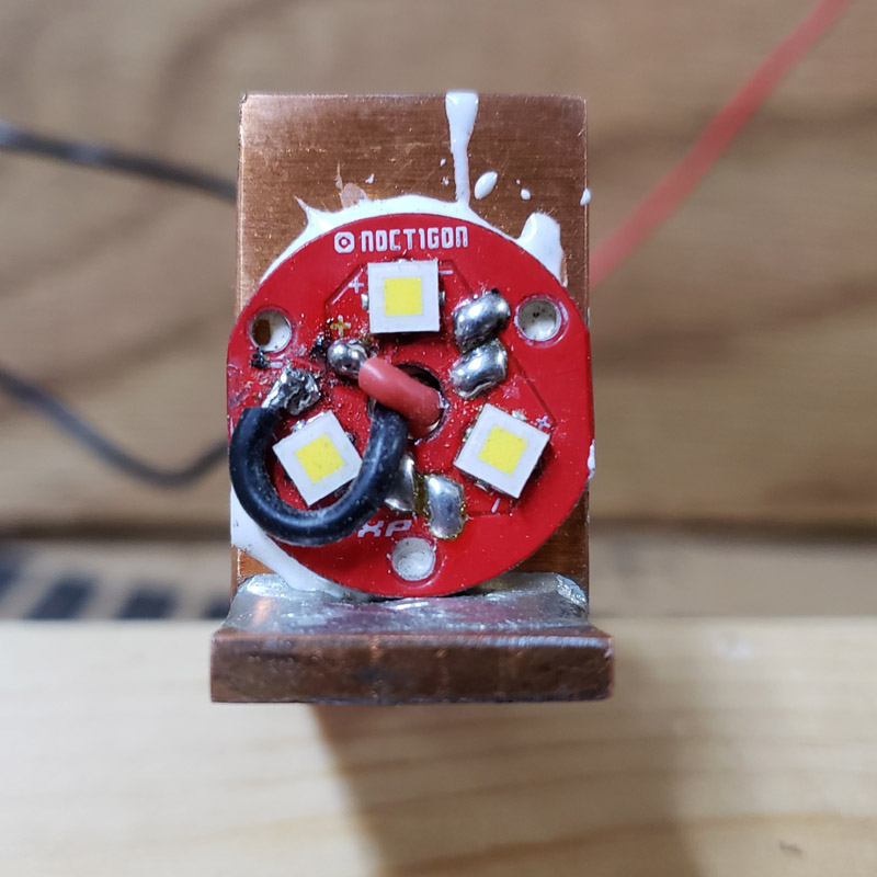
I mounted the rear mcpcb and soldered the power leads to it.
Next, I flashed the Qlite driver for the front LEDs. I mounted that driver to its position and cemented the mcpcb to its mount. The wires were soldered to the mcpcb first. Much easier to solder the wires to the mcpcb before mounting to the mass of copper. I contemplated drilling and tapping holes to use screws, but decided not too. I sometimes break small taps when tapping thick copper. These LEDs are not being driven hard and I don’t think I’ll ever need to replace any of them.


The black wire that is soldered to the copper in the lower left area (above image) is the chassis/carrier ground. THis will be connected to the cell negative and also to the negative battery connection point on the charger board. That too was difficult to solder. The electric soldering iron seemed to be impossible. I used the flame from a butane torch to heat that spot and flow some 60/40 solder onto the silver solder of the joint.
After the cement had set I discovered a small problem. Some of the adhesive seeped into the holes for the optic legs, preventing full seating of the optic. I have not decided how that will be resolved. Perhaps boring the adhesive out by grinding the tip of a drill bit flat and using a hand held bit holder.

Here are two views from opposite sides. The front end is to the left in the first shot.


In post #50 I mentioned the planned change from the first rear lens I glued up. I did make another one using two layers of 3/32” lexan material. I said it was 1/8” before but that was a product of a faulty memory. So next we have the laminated lens already drilled for the rear diffuser lens. The edges still need a little sanding clean up.
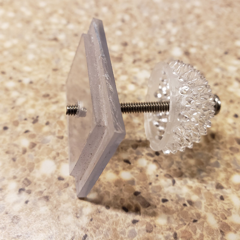


That is a 4-40 thread machine screw. I wanted to use a flathead style but didn’t have one long enough. I’ll have to check the hardware stores to see if I can get one.
Next is a view looking in the rear end with the carrier assembly inserted…

Then the same view but with the lens set in place. See the hole through the lens lines up nicely with the threaded aluminum rod…

… and next with the diffuser lens in place…
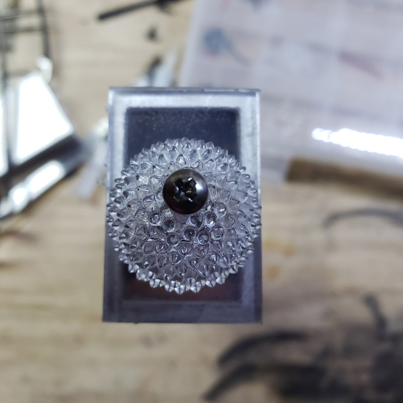
In case it is not obvious, I should mention the spikey diffuser is wanted so the red tail light will be readily viewed at an angle and not just directly from behind.

And lastly for tonight, here’s a side view of the partially assembled parts.
After each new soldering step, I have checked the driver/led and the front and rear both still function. I will be soldering the switch wire harness ito the drivers soon. Once the cell positive is wired to the charger and switch there will be one further operational check.
There are a few small things to complete in the carrier assembly before I can call the “guts” finished. Then it will be time to complete the detailing of the outside of the aluminum tube.
Thanks again for viewing and commenting. Queries are always welcome.
Nice work, MD. Coming along very well.
What in the world did that spiky thing come from?!
It is a LEDIL C15419_ZORYA-MINI
I bought it from Digi-Key
I found it when I was looking for parts for the lamp/lantern I built in this thread. I used one there and have a few extras. Ledil also makes a bigger version. This one is 24 mm at the largest diameter. The other is something like 55 mm and has a flatter curve. They are polycarbonate.
With all the spikes it was difficult to find the center for drilling. I used the tip of my soldering iron to poke a hole, then drilled it out. It worked out and I didn’t even have to use one of the spares. ![]()
Really nice work Don as well as creative.
This to me looks like a rocket powered hill billy sled.
Funny you should think that. When I first began visualizing this idea I was calling the part you are referring to as the “sled” and the aluminum tubing, the “tube”.
Anyhow today has been an exciting day.
First of all, I did grind the point off a drill bit and used it to cut away the epoxy that had seeped into the holes the optic is supposed to seat into. And I just realized I stuck that drill back in the index box. I think I had better remove it and insert a new bit before whenever the next time is that I want to drill a hole that size. :person_facepalming:
First a “before” and then an “after” along with a picture showing the optic fully seated.


Then it was time to solder the tabbed cell into the system.

Once that was done I plugged in the switch assembly and tried the front light. Success! The LEDs illuminated and I could run through the 5 levels. Then I clicked the switch for the rear. And nothing happened. No light. No smoke either, so all was not bad. But I was disappointed. I checked the soldering, wiring and all looked okay. So I removed the bolt and aluminum post that secures the rear mcpcb. Tried the light again and it worked. I tried a partial reassembly and the light worked. Tried tightening the screw into the post and the LEDs flickered. Inspection seemed to indicate that perhaps one of the led + pads was contacting the aluminum sleeve when tightening the screw and post. What to do?
I found a small nylon washer that would fit between the LEDs and would allow the 4-40 screw to pass through It would insulate the aluminum post from the mcpcb. I tried the LEDs and they now worked fine. I could run the rear LEDs through the various modes.
You can see the nylon washer in the next photo. (FWIW, the little washer is another leftover spare from the days of RC car racing. This is an internal piston part for one of the hydraulic 1/8 scale shock absorbers. Never throw anything away.)
Next was to try sliding the carriage (sled) into the main tube. Before that could be tried I used Kaptan tape to hold the cell and loose wiring in place. The sled slid in okay but when I plugged the switch module into the sled harness, I found two wire were too short. I could not slide the connector plug far enough to the rear to get the padauk top strip and switch assembly fully seated.
I removed the sled and cut and installed two new wires. These were wires soldered to the Deans plugs so it involved some desoldering and resoldering new wires. With the sled reassembled I reinserted it inside the tube. The switch assembly and padauk strip fitted. The light worked; front and rear both!

I’m just holding the loose parts together but the front and rear lights can be seen working.
So then after basking in that success for a moment I removed the sled from the tube and took the following two pictures to post here.

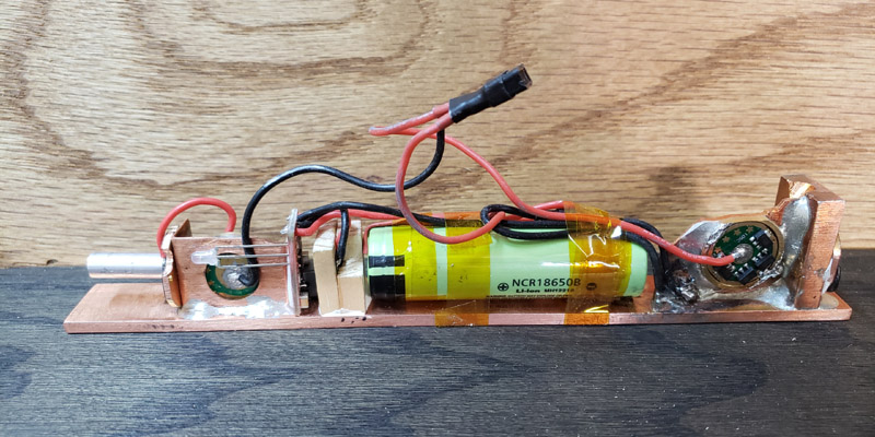
There is one detail to complete on the sled. Maybe two… my original intent was to glue the cell in place. Glue it to the copper carrier/sled. With that in mind, I did slip an extra piece of shrink wrap over the cell prior to soldering the wires to the tabs. I figured that would make removal, if necessary, better as then I may avoid damage to the primary cell wrapper. However, I may decide to stay with Kaptan tape, Maybe a few more wraps. What do you think?
Then I need to do a final trial assembly. In my excitement today I did not check the fit of the few screws that will hold parts together. Should be ni problem but I need to check.
Then I need to complete the exterior finishing.
Stay tuned and thanks for looking, thanks for the opportunity to have fun.
You: ![]()
Me: :o
This is awesome !!!
Great work Don ![]()
About the kapton, maybe adding some double face tape can help maintaining the cell in place and still be able to remove it easily!!
The double-sided tape may be the best idea. I have some 3M VHB tape.
I never thought of using it. ![]()
I meant to mention that the cell is purposely oriented with the positive end towards the rear. That way the + end rests against the wood block that encases the USB-C port and is thus insulated from the copper carriage/sled.
I also need to decide what optic to use in the front end. I have Carclo 10508 (medium spot), 10509(wide spot, rather floody) and 10510 (elliptical, which I have always liked for a bike light) on hand. :?: Probably do not need anything throwy for a simple general purpose walking light. :?:
Turning into a very descriptive with nice pictures great build thread ![]()
Nice detective work on finding the short Don. Things like that can drive you nuts. ![]()
I was so happy I found the problem within only a few minutes and that it had a simple solution. I was having visions of having to flashing and installing another driver
.
.
.
A small update tonight.
The mystery notch in the rear mcpcb will be explained.
The notch is for the indicator led for the charger section. The leads for the led position the led too far forward from the rear lens to be easily visible. I considered moving the led towards the rear, running some short extension wires. I could not come up with a mount for the led that did not also obscure the light output from the triple red XP-E2’s. So I decided to place the indicator led where it has been and using some fiber optics to route the light as a beam right to the rear. Doing that has helped a lot but it is not a 100% satisfactory result. The Ledil diffuser now obscures the indicator led output a little. It is more visible than before and that is a plus.
Here are two shots, much the same, with one indicating red as the charge builds and then the blue color which indicates a full charge. The charger cuts off at 4.19 volts. Pretty much perfect.
I used a length of heat shrink tubing over the fiber optic and the led.


I would have liked to make an “S” curve in the fiber optic to raise the tailend of the optic above the diffuser. However, the fiber optic didn’t want to stay curved and would need a holder or something to maintain the curve, while not obscuring the main rear facing led’s.
I did reassemble the carriage/sled into the tube, fitted the retaining screws, and everyhting aligned. I also fitted the switch assembly and checked the fit of those retaining screws; all okay there, too. As well the rear lens and diffuser was fitted and found to be okay. I did this using the elliptical front optic. That 20 mm diameter optic had to have the left and right sides filed down a small amount as the inside width of the aluminum tube is 19 mm and the optic is a true 20 mm.
No photos of that complete assembly were taken but there will be some more photos after the tube exterior receives more polishing and the padauk wood top strip is finish sanded and clear coated. There will also be a yet to be disclosed finishing touch to the exterior.
” MtnDon “, You know how to work it, we are all in a transe . ![]()
Don, wondering why you went to the trouble of grinding a drill bit to clean up the MCPCB holes for the optic? I’ve drilled that excess solder and flux out many times, too many to count, and due to the shoulder on the legs of the optic I never worried about overdrilling into the copper heat sink below the board. I keep it to a minimum, but the showing of copper makes it obvious the holes are clear for the optic. Doesn’t hurt anything and sure is easier than grinding a drill bit! ![]()
Nice imagination and implementation, getting the idea and visualizing it is the most important step of course… being able to implement is what makes it come alive! I have trouble with the vision part anymore. Have to wait for inspiration, can’t do it on demand. Writer’s cramp or something. lol
Sometimes I ask myself similar questions about why U did a certain something. Mostly there is no good answer. :person_facepalming: I agree, I could have simply drilled through the adhesive residue and into the copper a little.
In this case the choice was influenced in part by one thing. About ten years ago a local wholesale tool jobber went bankrupt. Everything was sold off in auction lots. Things like drill bits came in boxes of 10 to 50 bits depending on size. There were many part boxes in most sizes as well as full boxes. I bought hundreds of drill bits. In the sizes from 1/16 to 3/16, the easiest to break, going in 64ths, I got something like 500 bits. In larger sizes up to 6 to 10 of each. Pennies on the dollar.
Thanks for the kind words about the ideas and implementation. Some, many, of my ideas come to me in the early morning hours when I wake up.
Ah, ready availability. I get it. I sometimes use a 4-flute end mill bit for this sort of thing as well, by hand. But if I had a plethora of small bits, might well do the same as you and create a specific use tool.
I grab whatever works, ad lib with the parts on the table. Sometimes I simply can’t remember how I did it last time… sometimes I don’t even remember there was a last time! So yeah, consistency is not a strong suit for me due to my memory issues. You wouldn’t believe how often I struggle with whether the C1 is supposed to have a 10 value or a 1 value… geesh, hundreds of drivers behind me and every time is almost a first time. Keeps it interesting though. lol
Edit: For clarity… when I ask why something was done a certain way it’s usually to be sure I haven’t forgotten something critical. ![]()
Sometimes I can’t leave “good enough” alone. But then sometimes “good enough” can be improved upon. When I tried forming a curve on the fiber optic I used hot water. This morning I thought I could improve on what I did. I used the rework hot air part of my soldering station to heat the fiber optic and introduce a major couple of bends. That worked better; the new reformed fiber optic held the bends. I removed the first one by slitting the heat shrink tubing with an exacto knife and installed the new fiber optic with new heat shrink tubing.
Here’s it is with the pronounced direction change.

Here’s looking into the tube from the rear…

… the blue, fully charged” indicator on…

… and with the flat lens and the diffuser installed. The charge indicator is now located where it is much easier to see.

Next we have a picture showing the interior from the top with the switch assembly and top plate removed, but plugged together. Just in case someone wondered.

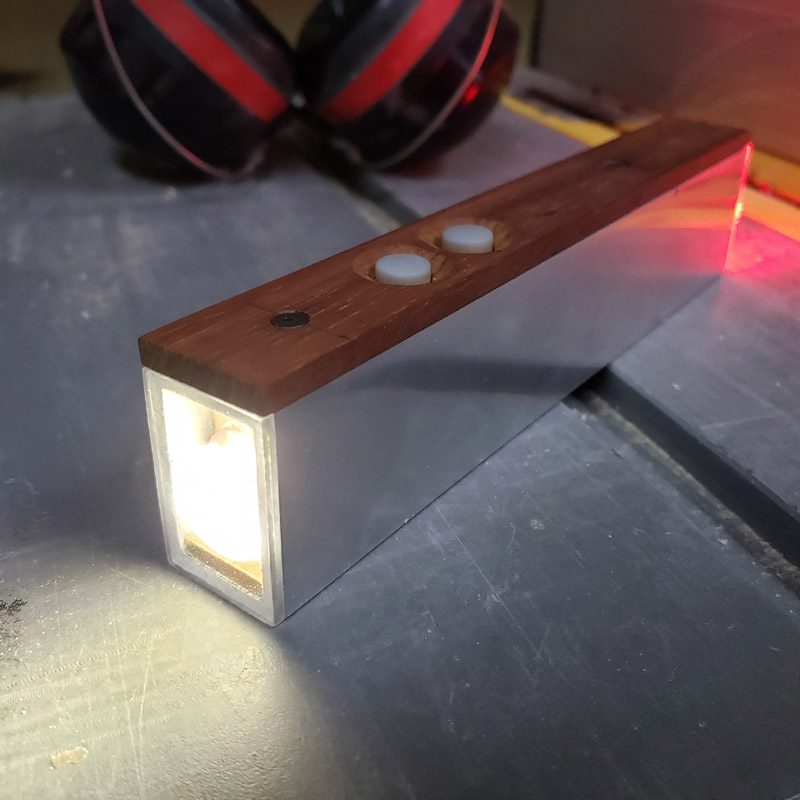
…assembled, but not completed. The exterior needs some cosmetic finishing.

… fully functional.