I’ve made a little halting progress over the past 2 days.
The padauk wood strip with the switch block would normally hve the wires soldered at each end to the various components. Not that I expect to be removing and reinstalling the top wood plate and switches from the main body very much I dislike a lot of what I consider unecessary desoldering and resildering. Therefore I have elected to use a small Deans plug to connect the three switch wires to the manin components.
Deans conectors are used a lot in RC aircraft, usually for control servos. I have a few left over from my flying days. I had checked them years ago and found that these little ones are okay at 8 amps. That is more than this light will ever operate at. So here is a shot of the male plug with power wires soldered to the connector. The shrink wrap is ready to be heat sealed once slid over the soldered joints.

Here’s the female part with wires soldered and plugged into the male plug

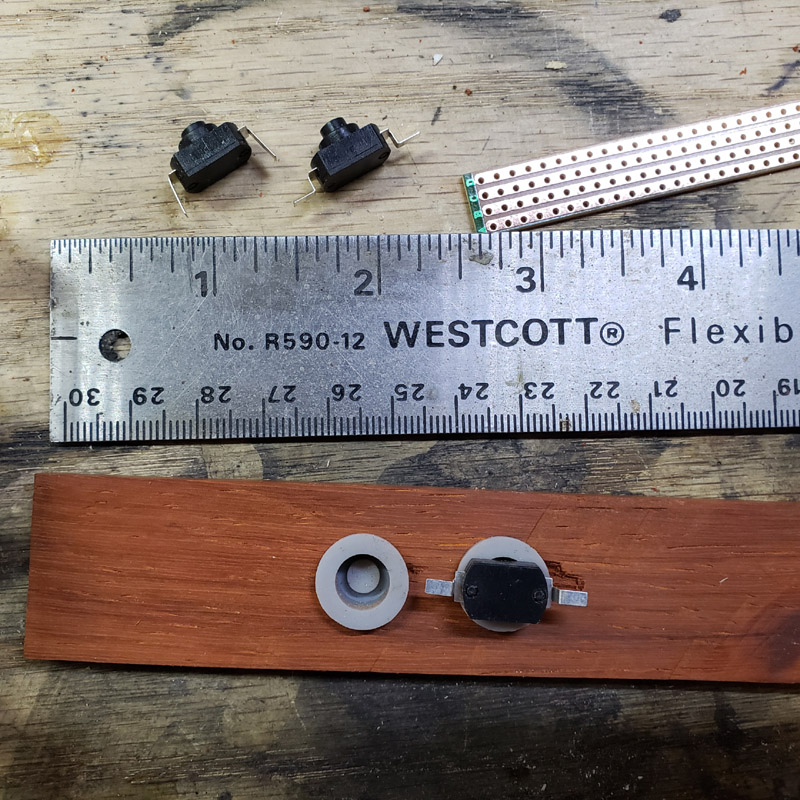
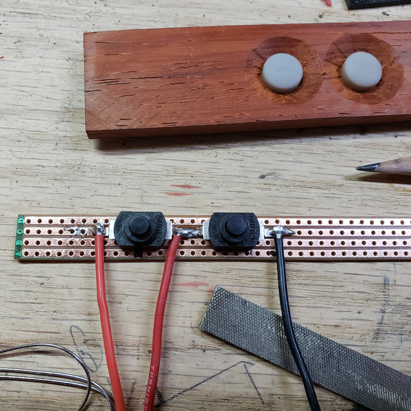
Here’s the male plug and wires soldered to the switches on the padauk wood strip

Holes were drilled through the padauk strip and the aluminum tube. The holes in the aluminum were tapped for 4-40 threads and the padauk countersunk. It fits! But needs finish sanding.

Here’s the TP5000 charger board with the indicator led soldered in place.

Here is the mcpcb for the rear red colored XP-E2 leds. It has been modified. I have tested it with the multimeter and everything will work even with the notch. The reason for the notch will become apparent soon enough.

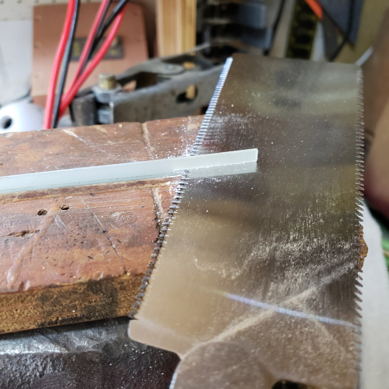
Progress comes with some setbacks at times. Several posts ago I showed the front “lens”, made from lexan, glued to the front end of the aluminum tube. The copper carrier slides in from the rear of the aluminum tube. There will be a similar rear lexan lens. However, the rear lens cannot be glued on. It needs to be removable. My first idea was to use a 3/16” piece of lexan instaed of the 1/8” I used for the front. That plan included cut a” “rabbet” “:Rabbet - Wikipedia(a notched out edge) around the perimeter in order to allow the lexan to be partially inserted into the tube. I decided that was a bad idea as trying to cut a 1/8” wide by 1/16” deep rabbet in lexan is more difficult than cutting the sand in wood, my usual media. So I decided to try gluing a lager piece of lexan to a smaller piece and creating a glued up “rabbeted” part. That was going to work it seemed after my test glue up. Howerver, the 3/16” piece npw seemed too thick; thicker than the front lexan lens. In the end I cut 2 new pieces of 1/8” lexan to make a new, and I hope, final, rear lens. I have included some pictures of the first idea and have e=nded the series with a shot of the final, glued up pieces.
I hope what I just wrote along with the images, makes sense.
The 3/16”lexan cut and sanded to aluminum tube OD size.


Trial fitting of th lexan piece that was to fit inside the tube, before any gluing

The thick and thin pieces glued up. And not to be used

The newly cut 1/8” lexan pieces. The outer sides of the larger plate will be cut parallel to the smaller and sanded to the exterior dimensions of the aluminum tube. I’m using a crystal clear expoxy and now have to wait for it to cure hard until more work on it tomorrow.

I cut both the copper carrier and aluminum tube down to their final size. The final length of the aluminum tube is 7-5/8” (194mm) This picture has the unused rear lexan lens shown. Disregard it; but it does give an idea of what the to-be finished lens will look like.

The final image for today, shows the shortened carrier with the charger board cemented to the heat sink area. The triple red E2’s do function. Hoorah for that.

Thanks for dropping by. More to come.