Starting of I would like to thank OL for again having the patience, time and forethought in putting this event on. l would like to also thank the sponsors for supporting our elder statesman here in helping make this an event which promises to bring out the best and worst from all the entrants in this comp.
Lets get down to business. On not knowing what to build I've decided to build a triple. The next question I had to answer was would it be based on P60 or C8 reflectors. As the old saying goes, bigger is better, I have gone along with the C8 reflectors. These will be most likely use XML-2s on copper in some sort of tint.
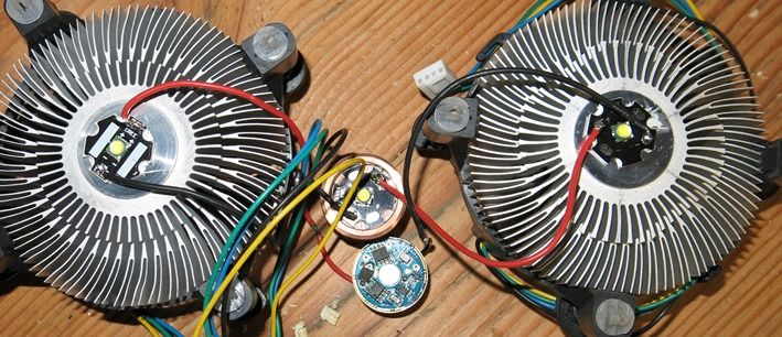
The following was the driver being used testing 3 leds to make sure it all worked.
As mentioned elsewhere the whole shebang did, bang that is. I do have a Bflex driver now that I will use but have no idea how so will be calling on help as the build proceeds.
A few drawings were sketched up and the nearest size camera lens I could buy is the basis for the layout of the components. A piece of 100mm round ally has been purchased which l suggest will do its best to kill my lathe.
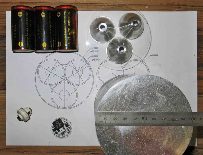
The switch is a Tofty which will be used to lockout the batteries from the driver in a tailcap switch to prevent parasitic drain on the 3 x 32650 batteries.
If anyone sees any issues or has suggestions (good or bad) with my build please let me know as most of you are aware my electronic skills do leave a little (lot) to be desired and the mind tends not to work with any sort of imagination at the best of times.
How this pans out from here is anyone's guess. I'm going to start, I think, with the pill and machine out the spots for the led stars. The outside will be turned and threaded to an undecided diameter for the reflector housing to screw onto, more than likely from the bottom and then the battery tube screws up against the reflector housing on the same thread on the pill. Confused? I am. 
Update 27.4.14.
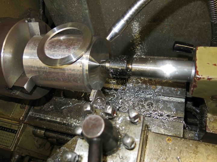
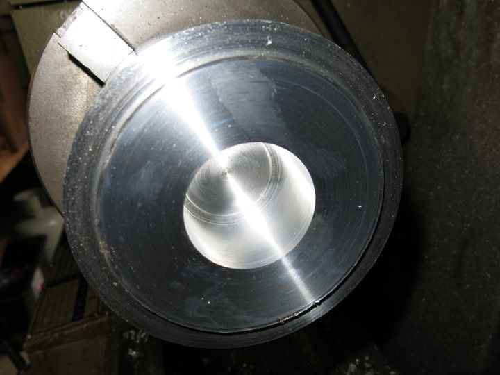
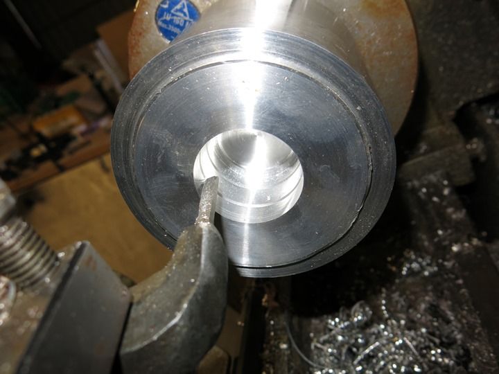
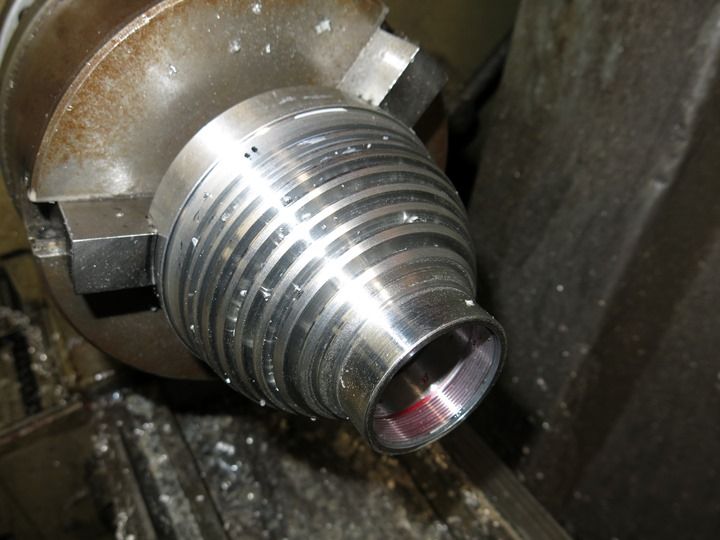
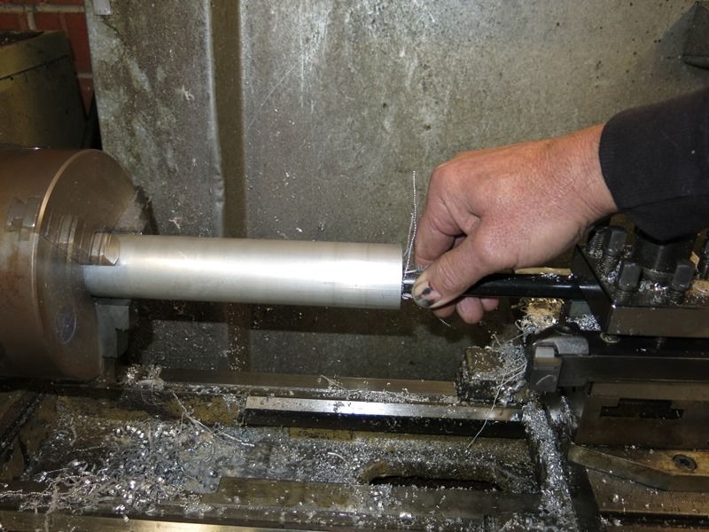
So as not to crack the glass lens and to locate the reflectors a plate was deemed necessary. This was made from the lump of 100mm diameter bar. The spacer on top was machined up as a spacer to sit against the chuck jaws to prevent me machining into them. My lathe made hard work at parting this of. The machined step is what the reflector locator will be made from.
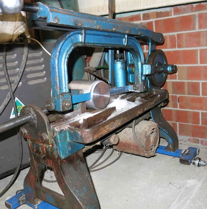
The older than I am power hacksaw was used to cut the locator of. This was then faced of in the lathe.
I believe most of you will know I have a new machine in the shed. Personally I call this cheating and will suffer any penalty's the judges deem that I be dealt. I have not used a mill with any length of time let alone had much training on using one (I did my apprenticeship in fitting and machining in 1979 and not really had anything to do with them since) so this is a very steep learning curve for me. Not having used a digital read out before I'm starting to wonder why all machines dont have one. After centering the piece in the chuck and punching in some answers to questions the digital read out asks you can proceed to machine things. I was astounded.
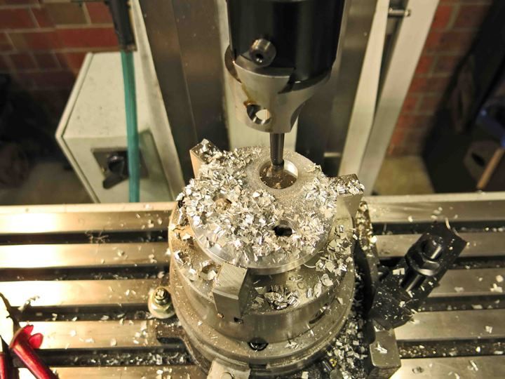
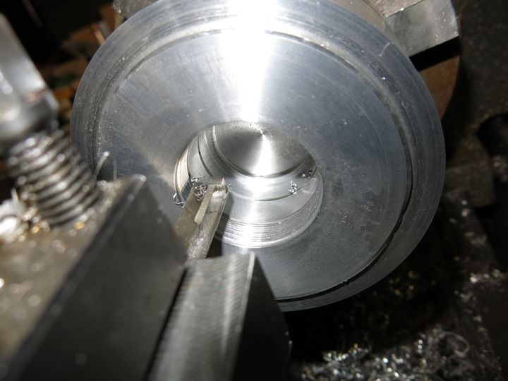
You can see the spacer in the bottom here to prevent me machining into the jaws.
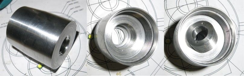
After all this and me s______g myself the whole time this was made. I did make the recess deep enough that If I have to use orings between the reflectors and glass lens because of something not right later on I can. Hopefully they will not be needed.
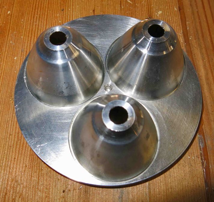
If its not apparent the hole is stepped so the reflector sits in the hole and located there without slipping all the way through.
Update 4.5.14.
Its been a busy weekend with visitors so I could only do a little on the light when I could sneak away.
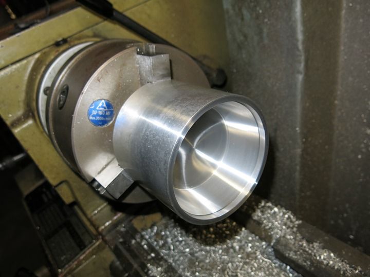
This is just taking shape as I go which normally ends in trouble for me. The head has been hollowed out of whats left of the chunk of aluminium. There's no removable pill in my plans at the moment so the leds will sit at the base of the hollow.
The reflector housing sits in nicely. I think I will machine the opposite end of the light which is the opposite end of this aluminium block so that I can hold this end in the chuck securely to machine fins, driver pocket and do the threads for the battery tube etc. I will then again turn this around back to this position and machine the bezel thread. Touch wood it goes to plan.
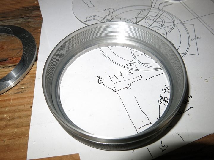
The bezel which was machined on the end of the same chunk of ally and parted of with great difficulty. There's an oring groove and recess down the bottom which the lens sits on to keep creepy crawly's and the elements out. The oring to be used was made from a piece of 1.5mm rubber oring cord glued together with cheap super glue. Lots of oring's I use are made in this manner.
This is a HD2010 having a snooze with big brother. Lets hope this light is just a little brighter than the HD2010. 
11.5.14 Update.
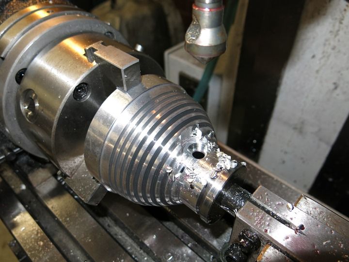
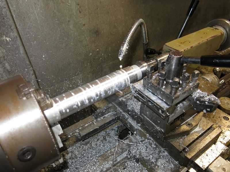
One step at a time. The 100mm dia bar was turned around in the chuck and machined out to suit the battery tube thread (not made yet) and a place for the driver to sit into at the bottom. Two holes will be drilled around the outside of the driver step for the wires to go through to the led side. A couple of circlip grooves to locate the nylon sleeve with the switch in it and thread for the mentioned battery tube will be done when I work out how to fix in the switch. After all this the outside will be machined. The shape will be determined by the bezel and switch location.
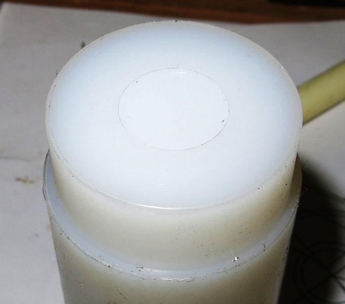
The nylon OD has been machined to suit the hollow in the ally bar and a step machined in the end for the + board to locate it. This will be the contact for the battery positive. The stumbling block here is the switch will be mounted in the side of it. I just dont know how yet.
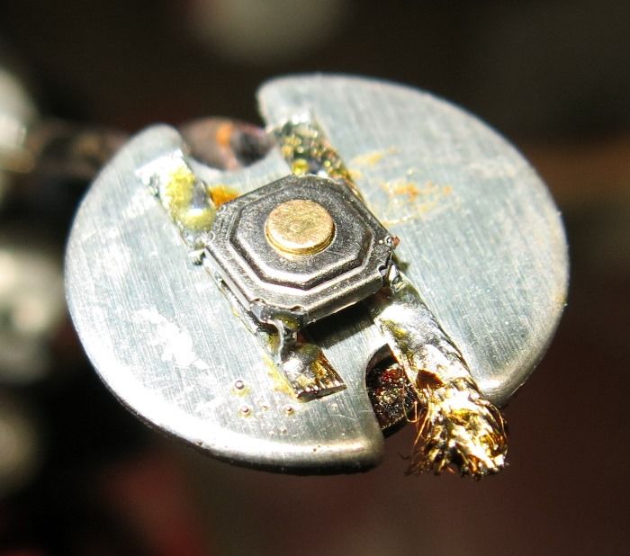
This is my second attempt to mount some contacts onto the switch. It is solder wick soldered all the way along and then soldered to the contacts on the switch. Wires have since been soldered on. It beats the c__p out of me how you guys solder driver boards etc up. A few choice words were emanating from somewhere just trying to line everything up which is why my first attempt failed.
Looking at the picture now this is the discarded one.
And finally for today is the bits that will soon be all working in unison on the switch end. The machined part of the nylon is sitting in the housing.
Update 30.5.14.
Today I had a good run and have nearly finished machining the head. Hopefully all thats left to do is drill some holes for the wires from the driver to leds. The sequence the pictures are in is the order that the machining was done.
Firstly the grooves were cut for the circlips that will locate the switch assembly. The tool used is probably older than me.
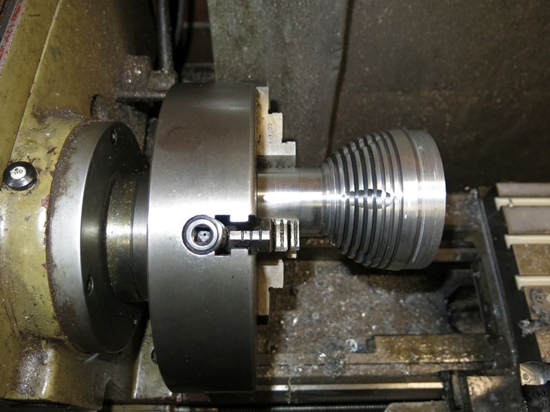
The thread was then cut for the battery tube that has not been started yet.
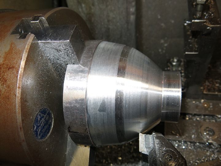
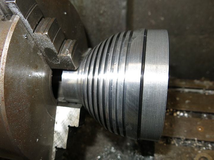
The head was then turned around in the chuck to profile the head. I did not want this to look like a toilet plunger with the short reflector area but large diameter. How I got around this will become apparent in a few pictures.
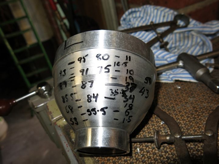
Next was the marking out for the fins and how deep they could be machined. This was measured up the old fashioned way.
The head complete with fins and this time I did not cut it in half. OL will know what I'm talking about.
The head was removed from the lathe and set up in the mill to machine a space in the fins for the momentary switch.
And then back in the lathe for the thread to be machined for the bezel to screw on. The bezel screws up against the step where the oring is and buts up hard inside. It gives it more a smoother shape with the bezel screwed on. Thats all the original stock of aluminium I started with gone.
Update 9.6.14.
Work has been progressing steadily the last week or so and just when you think the machining is close to finished, well you know how it all goes.
The battery tube was next on the list, well it would of been if there was a list. My largest boring bar was not really long enough being held by only one bolt.
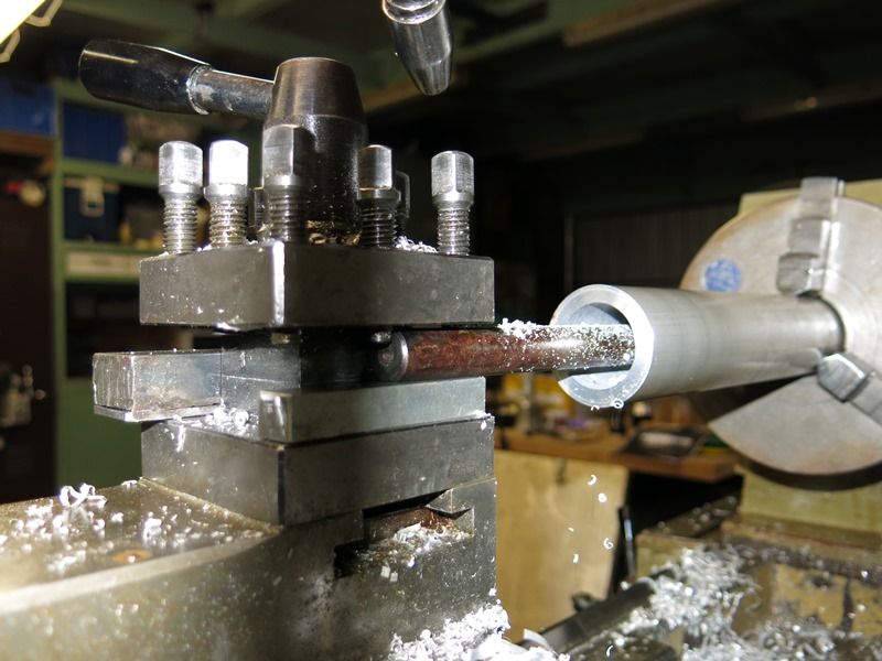
The latest in anti chatter technology was used at this point. It proved totally unreliable but was all I had to work with.
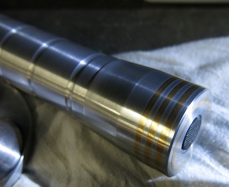
The thread for the tailcap has been machined and the OD is being turned down here. Its funny the finished tube does not look to dissimilar to buckets.
The tailcap was turned up along with the switch retainer.
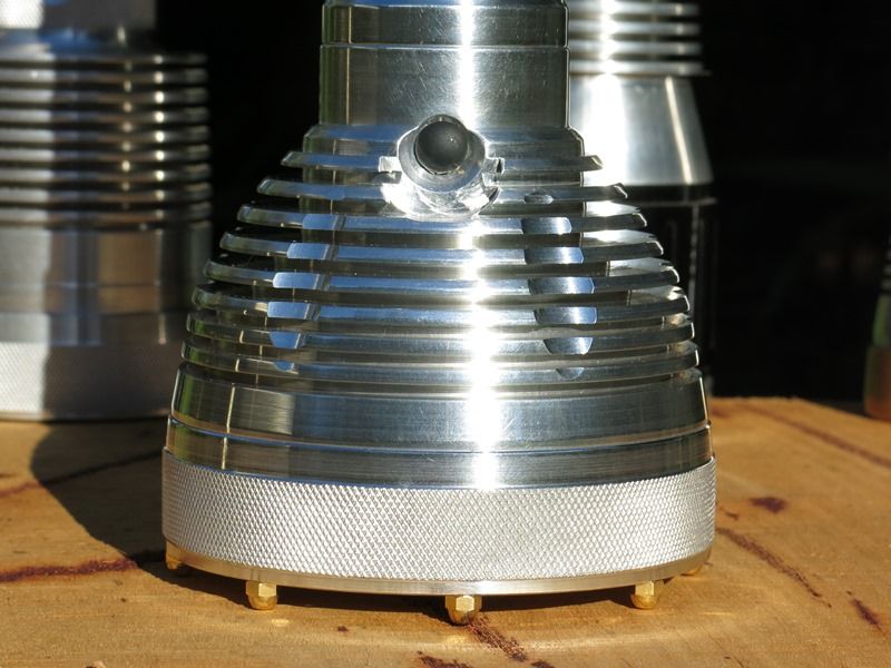
It was decided some bling was needed as I was trying to stay away with lots of knurling on this light.
If I get time I will machine some grooves in the tailcap for a little traction and add some nuts to the end for tailstanding. The same nuts are being used on the bezel. No pictures yet.
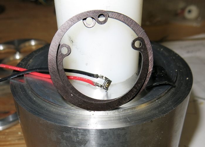
It was decided that the led stars needed to be solidly located to stop them turning. This was not as easy to machine as I thought. The stars still need to be seated in the holes.
The plan is to have all the machining and assembly finished this week so that the wiring can be completed next weekend leaving a weekend to fine tune it all.
Update 15.6.14.
After a couple of set backs we are back on schedule, well as far away from schedule as possible but we'll get there. Some of the damage cannot unfortunately be undone. The machining is finished.
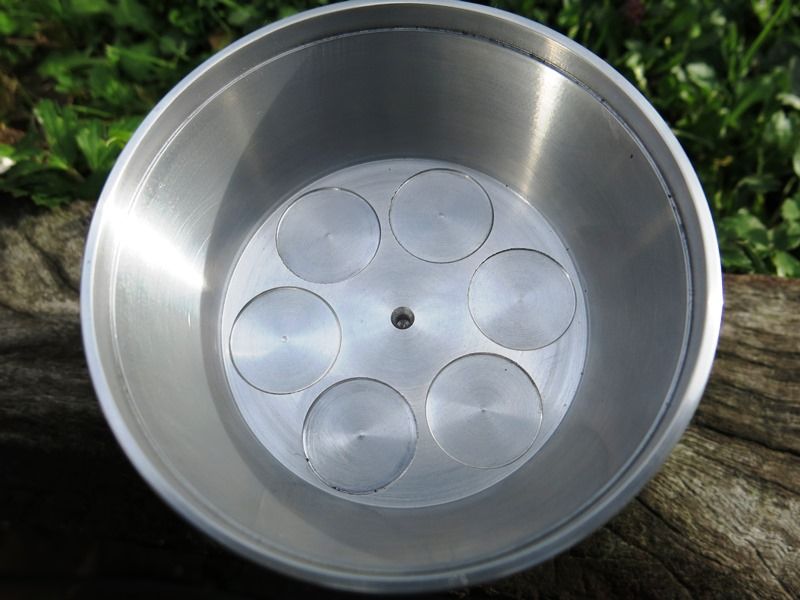
The recesses for the stars above was a miserable failure. There was no way l could get the base flat. I have watched you guys do it a hundred times and take my hat of to you for the finish you get. The decision was made to start again.
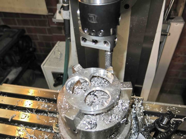
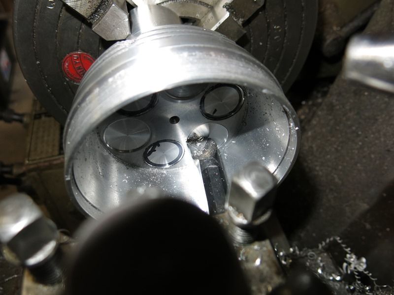
A spigot was made up to hold the head in the four jaw chuck. You can see how far offset the jaws are where the head is set up center with one of the recesses is to be machined. These were marked out in the mill.
This shot shows the boring bar used to machine the spot faces.
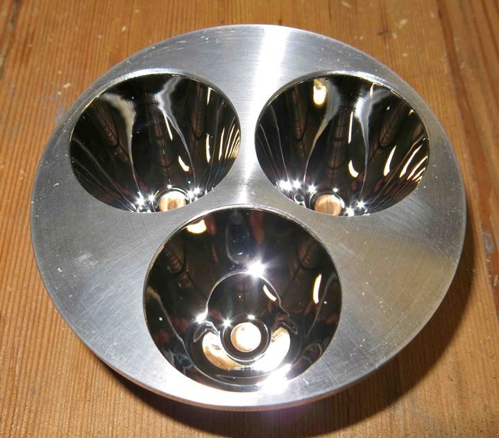
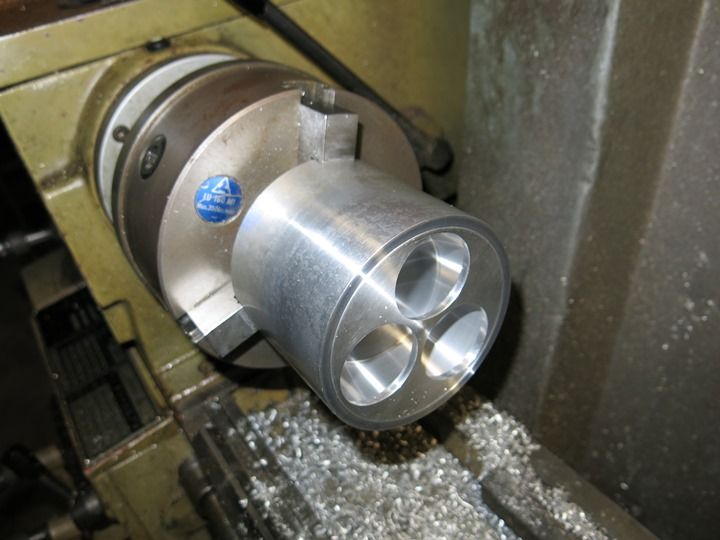
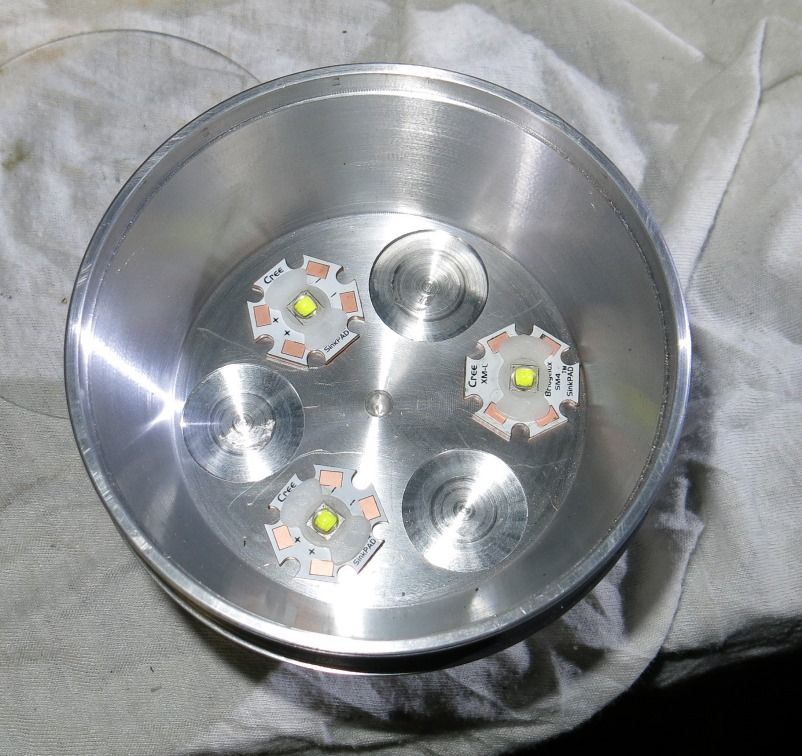
And the finished product. The three original holes were cleaned up for aesthetics.
Next week with any luck we should have an operational flashlight.
Update 21.6.14.
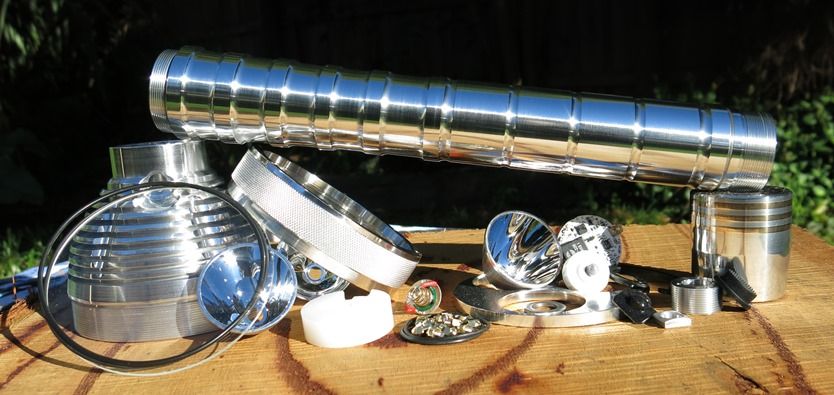
The light is all but finished. All the components that went into this light bar the led's. They were left forgotten in the shed which is why they may have revenged this.
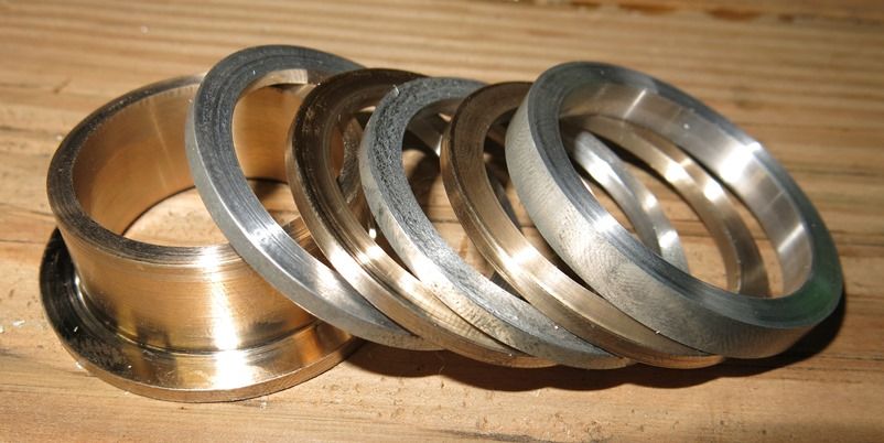
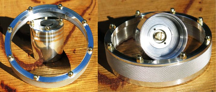
The acorn nuts are 3mm and made from brass. The tailcap assembled with the Tofty switch. The tailcap insets are made from bronze.
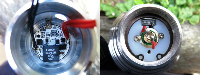
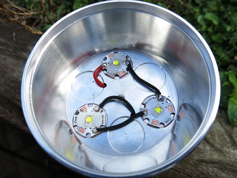
The driver installed. The earth strap is 3 thin pieces of brass joined together and screwed directly to the head with a 2mm cap screw. The driver is supplied with double sided heat tape which is also holding the it down. The nylon switch retainer also has the positive spring mounted to it. The wiring from the back to the driver and from the spring to the MPCB? is 22AWG wire doubled up. The switch ended up being from a SolarForce forward switch modified to be momentary.
The work place. The top led failed shortly after getting the light operating. The tint was 1A. The only led I had left to replace it was a 0D. All wiring is 20AWG.
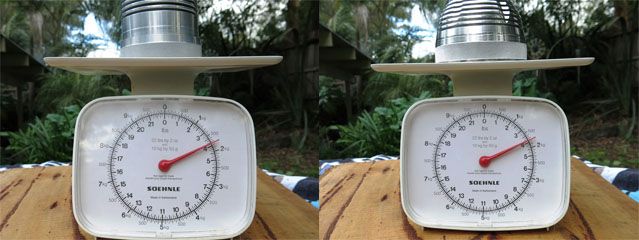
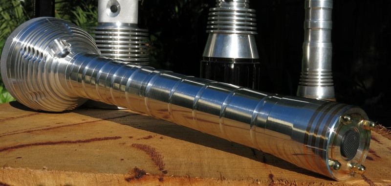
The light itself ready to goes with 4 x 32650 batteries installed weighs about the same as the Monster light running 3 x 32650s. The loss of the copper pill helped a lot keeping the weight down.
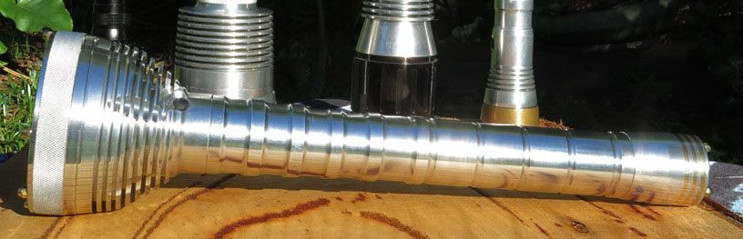
Its a nice winters day here today to post these final few for now pictures.
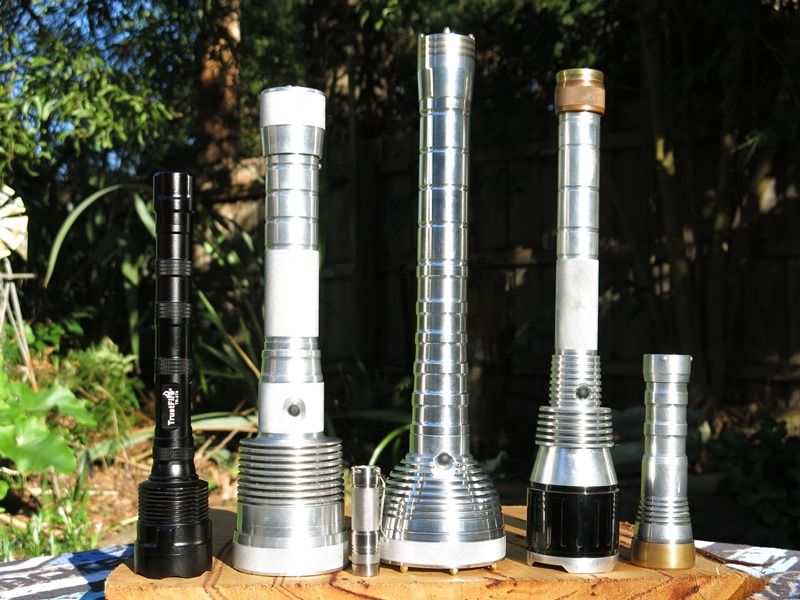
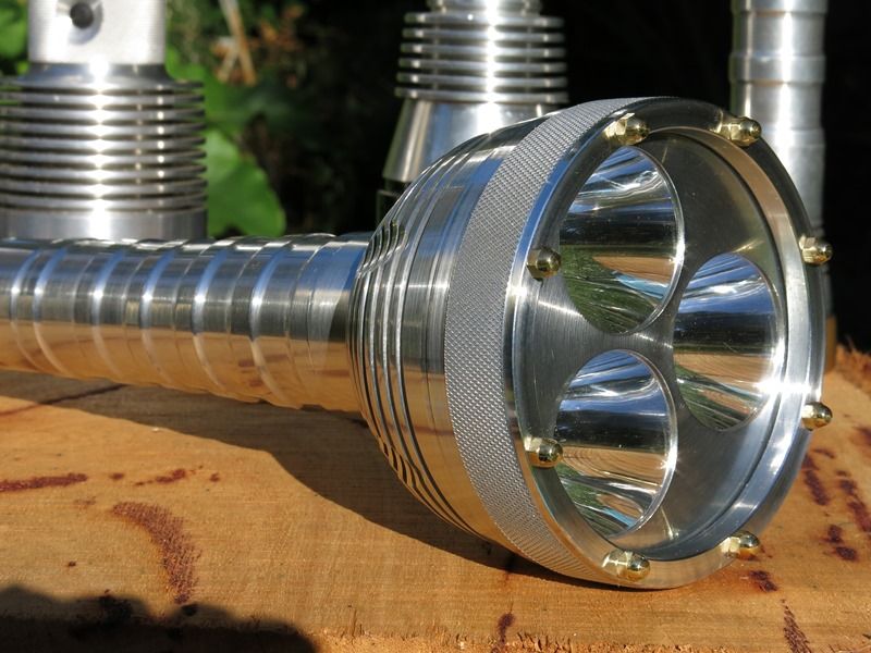
Left to right. My only other multi emitter light, Trustfire TR-3T6, Monster light, Eagletac D25C TI, this light still looking for a name, Defiant Super Thrower (head only), and last years build with the same C8 reflector as used in this build.
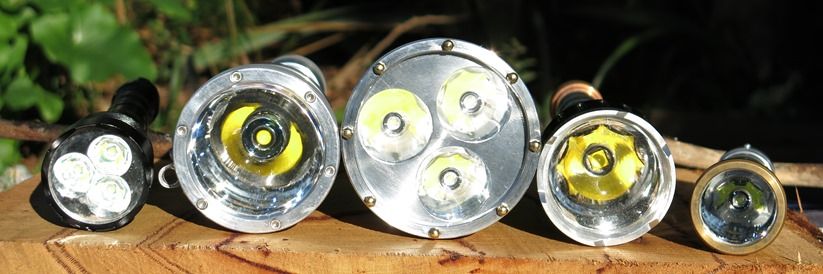
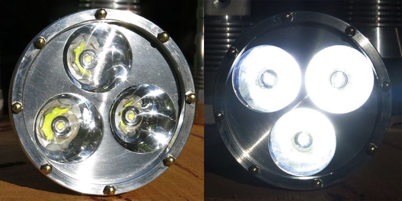
And from the front end.
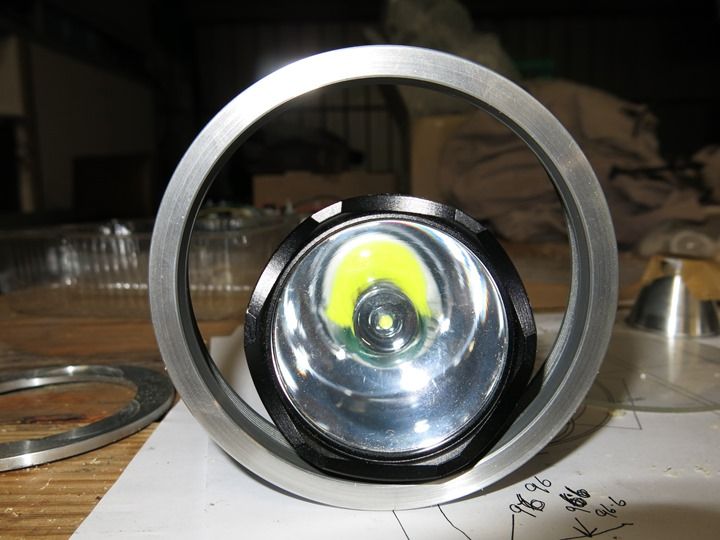
And finally some pictures that don't need my waffle. It works.
23.6.14.
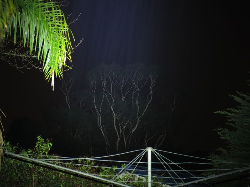
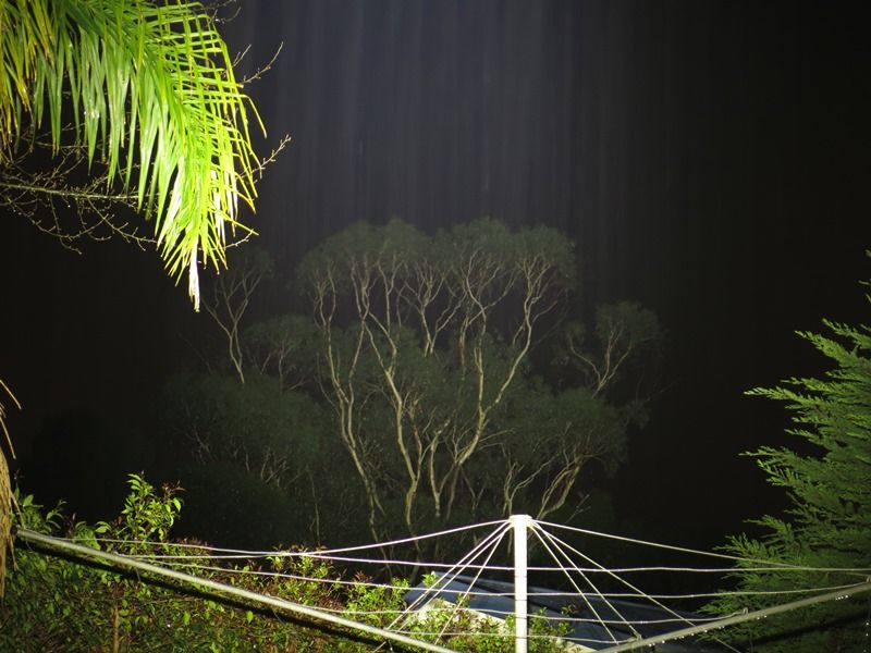
With a lot of help from RBD the light is up and running to its full potential. Thanks. Its bucketing down here at the moment so the shots aren't the best and the TN32 I have on loan has decided to stop working. The tree through the rain in the distance is somewhere around 110 meters away.
First up is last years comp light which is running an identical reflector. Tailcap current is down to 2.5 amps. It really wants disassembling and all the contacts cleaned up as it normally runs well over 3 amps.
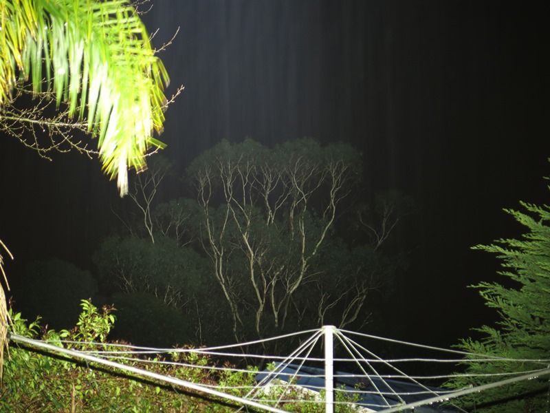
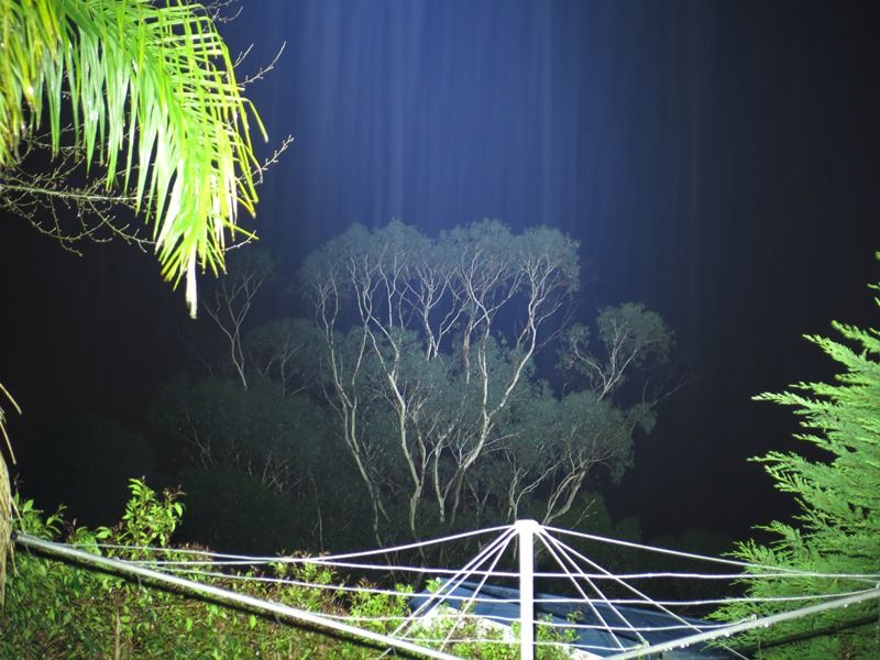
The proverbial and Mr reliable HD2010 at 5 amps.
Thrunite TN35.
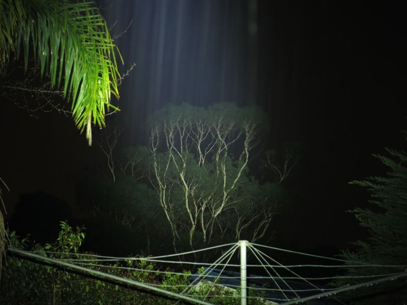
Monster light (9 amp driver, DX lens and MTG-2).
Defiant Super Thrower (dedomed XML-2 0D and 5 amp driver).
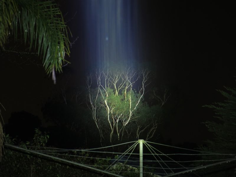
And finally the light that had no name and not sure if this will stick C83 6.6. Three C8 reflectors running at 6.6 amps each.
After the frustration of not programming the driver correctly and finally getting it right my first words were, not that I knew what they meant at the time was WOT WOOT WOOT, only because I've heard members say it so many times here when something was good. This thing out monsters the monster light.
In the future the only other mod I will do to this light is ad some mounts for a shoulder strap but for now this light is done and dusted. I will do temp measurements, run times and light meter readings as well not that there mods.
To all the entrants in the OL 2014 three months of frustration and woots I'd like to say thanks again for making our elder statesmans comp the success that it has been. The effort put in by all I believe has been outstanding and the creativity that has gone on does not happen in any other place in the universe. To you all, Cheers.