One step ahead - I plan to wrap the can with aluminum flashing sheet before soldering and using aluminum wire. Fortunately I have a bit of experience soldering stainless tattoo needles to stainless bars. ![]()
![]()
What could be more of a testament to the ingenuity of man than using bones as tools to make an advanced piece of LED lighting equipment. ![]()
Looks awesome, all the best for the build!
Man, seeing this I am happy that I don’t have to make lights like these and just can follow the standard procedure with my machine made lights. The amount of improvisation of all the handmade category contestants is absolutely amazing.
The .050 copper for the radiator housing and .125 copper to replace the thin sheet of copper at the base of the heatsink were delivered today and the brass tube should be here monday. Photos of the cooling assembly will be posted tuesday.
My goal is a light that takes the srk style light back a few steps and incorporates features even the original light that inspired it didn’t have. It will use 4x C8 reflectors un-cut and xhp70 emitters positioned in a way I hope will reduce the ‘hole’ present in lights using these emitters and smooth reflectors. Due to the active cooling it will include a diverter that will direct air flow away from the user to allow left or right carry. Due to the weight it will include attachment points for a shoulder strap and a tripod mount as near the balance point as possible.
Due to the lack of available threaded material in suitable sizes I am considering a few unusual methods to attach the battery tube to the rad housing including spring-loaded pin or cam mechanisms. It is critical (to me) that the connection from the battery tube to rad housing and head to rad housing be watertight. The switch will incorporate a membrane to eliminate it as a leak point. Though not intended as a diving light if I achieve my goals, with the fan removed and power connector capped it will work underwater for as long as sufficient charge remains.
Knowing I am a newcomer to this forum I have little hope of winning. My motive is to challenge myself, to use my abilities that have been idle far too long, and in the end hold in my hand something that I can be proud to say ‘I made this!’.
Please pardon the multiple posts. I’m hoping to reach the point where another page is necessary and start posting links to counter slow page loads due to build photos.
Lots of different big brass plumbing fitting for tub and sink drains. Let me know what size you need and I can check at Bateff salvage next time I go.
Your thoughtful offer is encouraging and very much appreciated but the idea is a build without outside assistance. In the early planning stages I planned to use threads from bathtub overflows but unfortunately lowes and homedepot in my area seem to have excluded them (chronically out of stock). :cry:
The competition is in the imagination and execution, helping each other with parts is encouraged. Scrap yards where they sell brass by the pound is more fun anyway if you want to look for yourself.
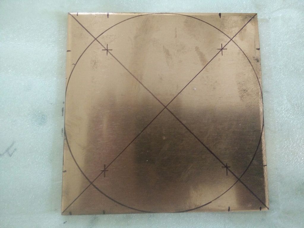
A bit of progress. I started with a 4” x 4” x .125” piece of copper sheet. Here it is marked for positioning of the heatsink and a 4” diameter circle outlined using a coffee can.
I decided afterward that I wanted a bit of space between the head tube and the heat spreader to reduce heat flow to the head and increase heat flow to the heatsink (radiator). I cut the first corner with a hacksaw which was too dull for the task. The other three corners were cut with a rotary tool and diamond coated wheel to create a roughly octagonal shape. This was then covered with packing tape to preserve marks to aid in positioning the heatsink and minimize marring by the vise as shaping is done.
Surprisingly the file work took less time than cutting off the corners thanks to a file Ieft in the barn behind my mother’s house by the previous owners that I’ve become quite fond of after using it on a variety of materials. The result was a very slightly egg shaped disc with a smooth transition from 95.81mm on the x axis to 96.06mm on the y axis. For the final size I used the bottom of a miracle grow sprayer bottle, outlined it using a fine sharpie, and gradually filed my way around with the piece clamped in a bench vise. I used the hollow in the bottom of a sherwin williams glazing compound container to get an idea of how badly out of round it was. When it looked close a bit of sanding with 400 grit wet paper to eliminate file marks and I call it done. After checking it with my calipers I found a .25mm (.0098 in) variation from round using such crude techniques (eyeballing it) which makes me feel pretty good about achieving my goals.
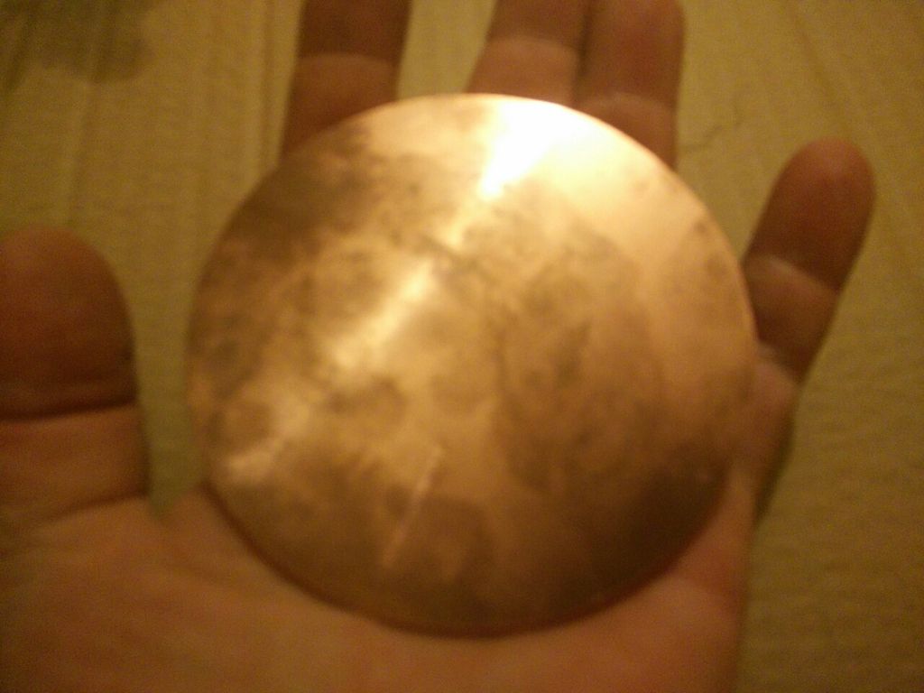
Face shown is the side to be used for contact with the stars. The other side still has the lines for heatsink positioning.
Below is a photo of the separator/attachment plates. The one on the left will be mounted on the driver side of the heatsink/radiator and serve as an end cap for the rad housing with the copper wrapped around it. The one on the right will be mounted behind the copper heat spreader and serve as an end cap for the head tube that will wrap around it. The square marked will be cut out to fit around the hs/rad. While making the cut with the dremel on the first corner the shaft on the mandrel broke. The hacksaw blade on hand isn’t much sharper than a butter knife so I resorted to a really low tech method. I bent corners of the pieces the circles were formed from and used a file on the bend to remove them and gradually filing my way around worked toward the marked circles.
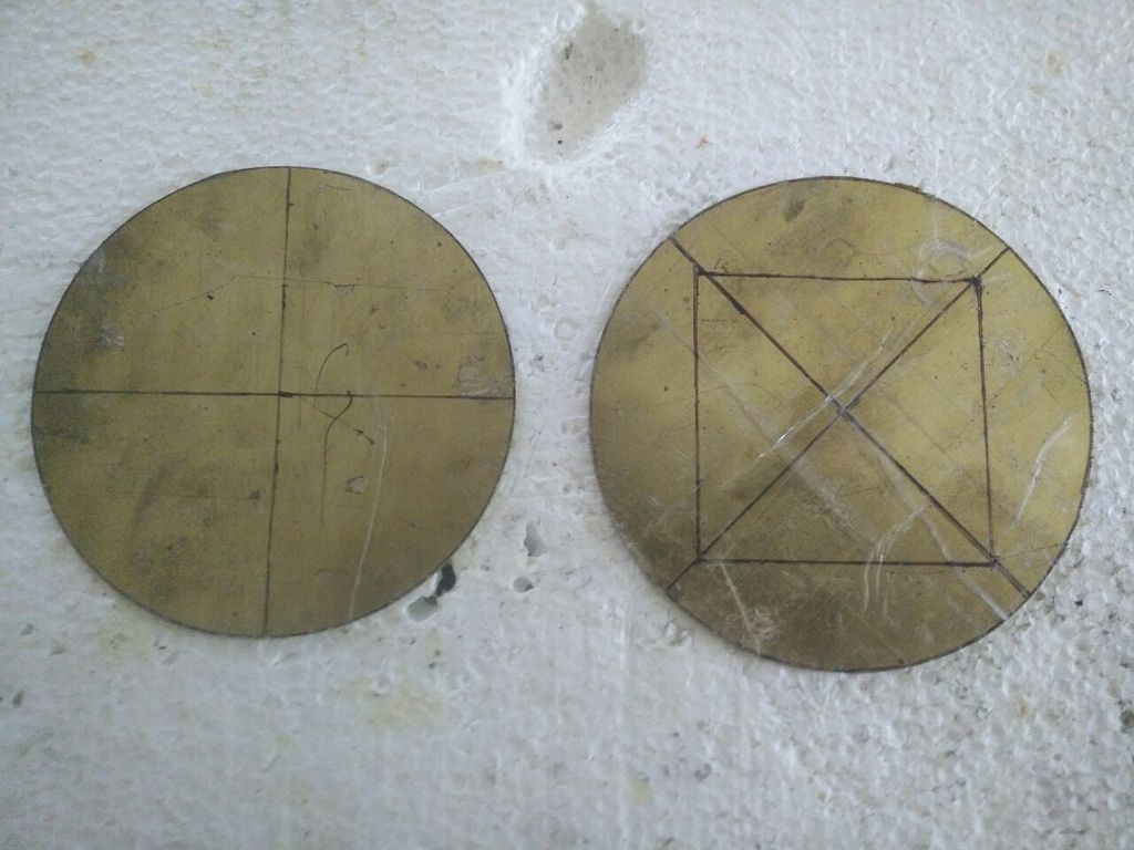
Update: a little more file work and diameters tested at 45 degree intervals
Left: 101.52mm to 101.6mm Right: 108.45mm to 108.51mm
Variation less than .1mm - I’d say that’s close enough to round.
Looking rounder. ![]()
I have trouble getting things that round in the lathe. Good work. ![]()
Thanks MRsDNF! New page! A disc isn’t too tough with a decent arcing motion with the file. Achieving a cylinder or taper over a length necessary for something like a cane is a different matter. While I work on this I will also be working on another light (a 4x 28650 powered lantern that was my other choice for entry) and a cane to replace the one I made for myself I gave to a friend and neighbor.
Now the cane would be a great place to add a light. Would to like me to delete post #32 so you can have lead post this page?
Post position doesn’t matter. My next photo post will be of the radiator assembly parts and process so there will be a good number of photos. Before that I still have to fabricate some parts and devise a way to hold it all togerher during the soldering process. One option I’m considering is copper rivets. They would hold the parts together, could be made watertight with a bit of solder around the holes to re-flow as the assembly is heated to solder the joints, and they’d look good.
Edit: Maybe I’ll order some 1/8 round copper and brass rod and use pins like those used to help affix knife scales. Copper for the brass on the head and brass for the copper on the radiator housing for more contrasting color points. 1 ft of each would be more than sufficient.
Edit2: after posting my previous comment I remembered that a while back I ordered some brass for pins to mount handles on some Camillus blades. 4 10 inch pieces of 1/8 inch brass on-hand. That means I just need copper. Maybe the scrap yard will have something. 12/3 romex type wire is too thin but 8 gauge would work.
Edit3: 2 ft 8 gauge solid copper wire ordered.
Edit4: 2 ft of 8 gauge was cheaper than 6 inches of 1/8 copper rod for knife pins so I’m satisfied. This build is putting to use materials intended for use on other projects but not used. The brass sheet that will be used for the head and elsewhere was originally acquired to make sleeves to reinforce certain points on a cane. That idea was replaced by use of camo 550 paracord with several core strands removed then impregnated and coated with epoxy.
My original plan was to enter a cane with a light but the ones I make take so long it wouldn’t be done in time, especially considering a feature it would absolutely need - a balance and pivot mechanism to maintain beam direction as the cane moves during use.
Quick test of pins made from 8 awg solid wire. I didn’t take the time to clean up the ends since I was just joining two scrap pieces of brass. Very secure and after soldering the joints will look good and with luck be watertight. The ends inside will be coated with solder and the perimeter of the outer ends will also be soldered as will the inner and outer seams.
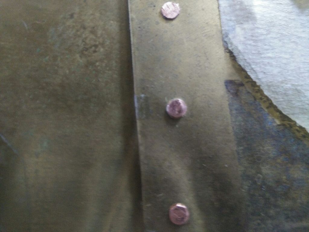
In the final joints the brass pieces will not overlap and will be attached to a piece of copper that will protrude slightly as an anti-roll feature.
Cool idea!
Looking at it again I think thicker wire will stand out more. If I use #4 copper wire the pins will look more like rivets. I had to do some shopping so I stopped at a hardware for 2 ft of #6 and #4. Here’s a piece of #4 between two of the #8. No finish work to the end since it’s a test.
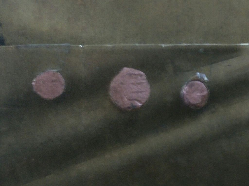
Without something for scale all I can tell is its bigger. I’m sure you know this but be sure to get bright, clean metal before placing them or the solder won’t wet no matter how much flux you use.
Definitely plan to clean all metal involved before soldering. For size, the smaller pins from #8 wire started at 3.25mm (.128) and are about 3.8mm (.150) after compression. The larger pin from #4 wire started at 5.15mm (.208) and is 5.65mm (.222) after compression. The tube containing the reflectors and emitters will be 63.5mm long (2.5 in) and around 112mm in diameter (4.4 in). With that much brass the larger pins would visually tie together the brass and copper better.