Until now I have been making high efficiency drivers for single cell flashlights, with good power for the size but nothing really crazy. Due to space constraints I’ve always used DC-DC converter integrated circuits, that is the DC-DC controller and the power MOSFETs are contained in a single package allowing small sized power circuits, for example the MP3431 boost converter or TPS62867 6A buck converter.
At higher input voltage than single li-ion cell there are relatively high power buck converter ICs available, like the 20A buck I used in my cascaded boost+buck driver, but that wouldn’t have been high and efficient enough for my project, the solution is to use a buck controller with external MOSFETs, allowing to use very low ON resistance FETs for lower conduction losses, and low switching frequency for low switching losses.
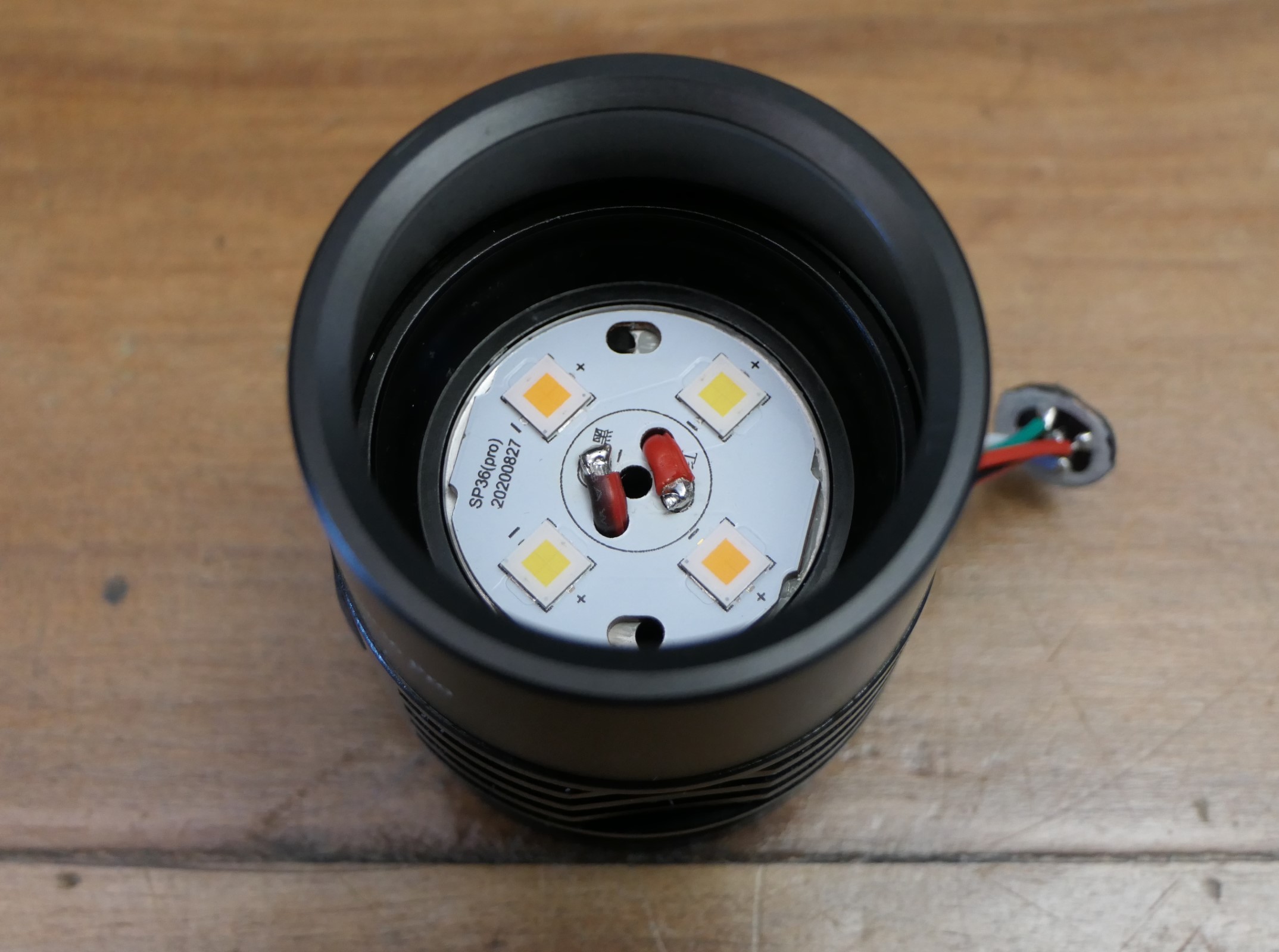
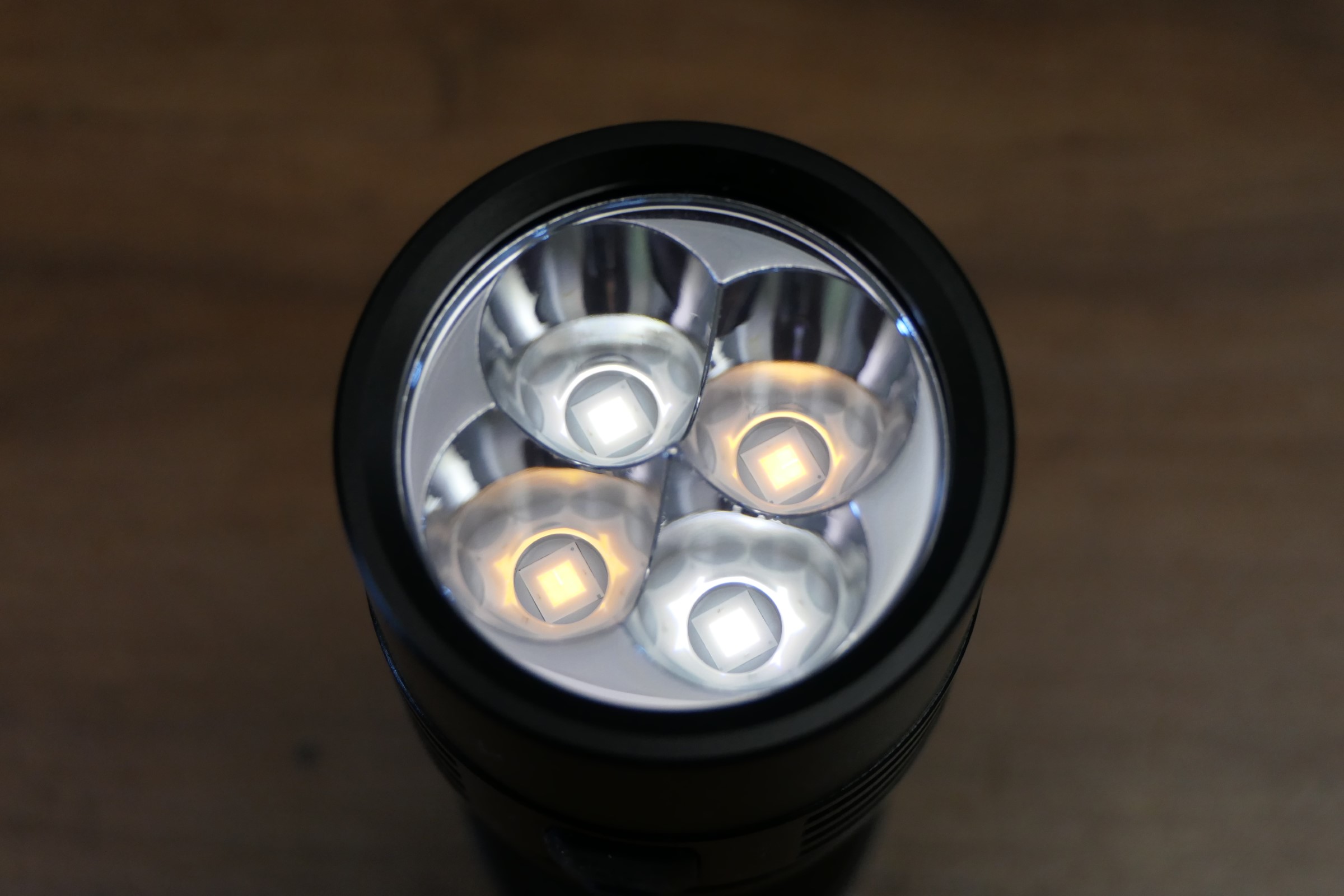
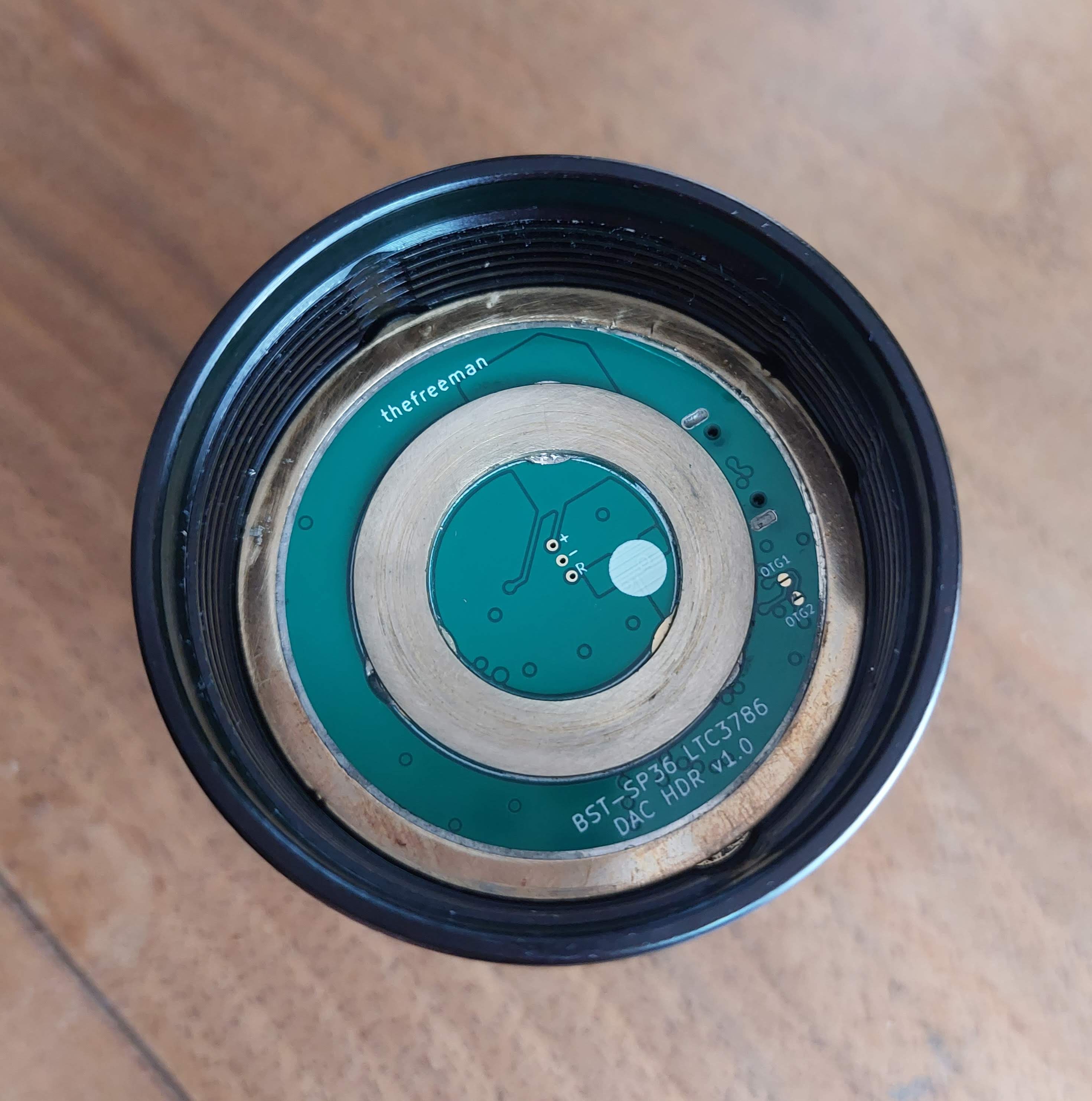
For the dev platform I chose the Amutorch DM80 for a few reasons :
- 3x21700 cells in series providing high enough voltage for full regulation and good amount of power.
- 8xSFT40 which can be relatively easily replaced by XHP50.3 HIs with MCPCB modification, originally 2S4P (6V) to be converted to 8P (6V).
- it was in promo at 100€ instead of 150€ or something like that.
-
@Haukkeli was willing to buy and estimate if the host was suitable (measurements) before I purchase mine, actually he’s the one who convinced me to go with that light

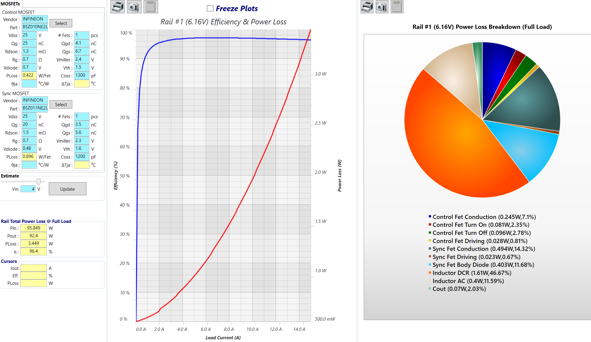
Once I got the measurements I started designing the driver, for the buck controller I chose the Linear Technology/Analog Devices LTC7803 :
- Vin 4.5 to 40V.
- small size QFN-16 3x3mm.
- can sense the current from the inductor DCR instead of a current sense resistor, lowering losses and saving space.
- easier designing with LTpowercad.
- actually available as opposed to many TI controllers.
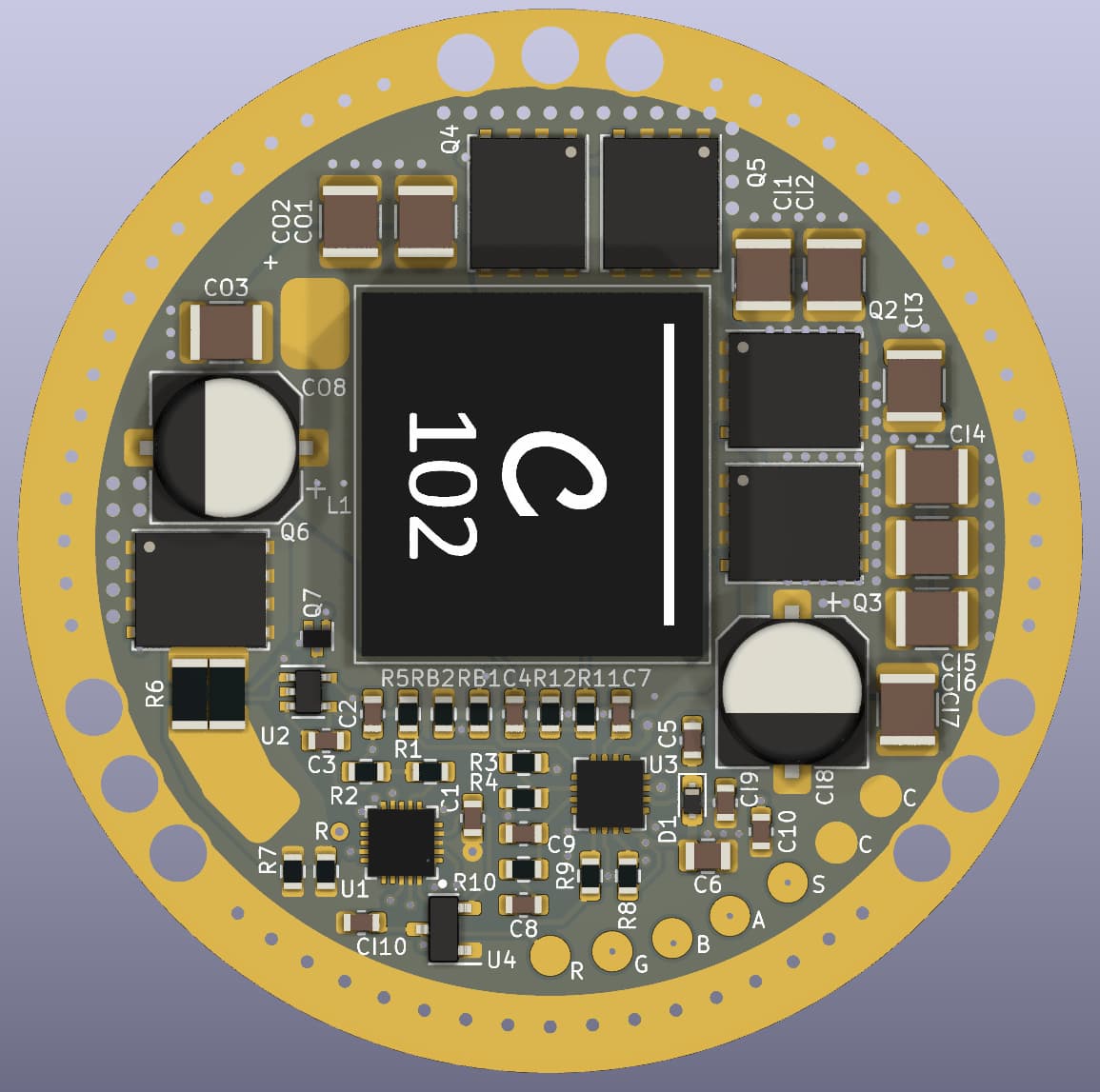
Initially I wanted to go with a dual phase controller, which means two inductors and two pairs of MOSFETS, dual phase would have allowed potentially more power and lower amount of capacitors but the available height was not enough (8mm) for suitable inductors (e.g. XAL1010, 10mm high), so I went with single phase and a XAL1580 (15x16x8mm).
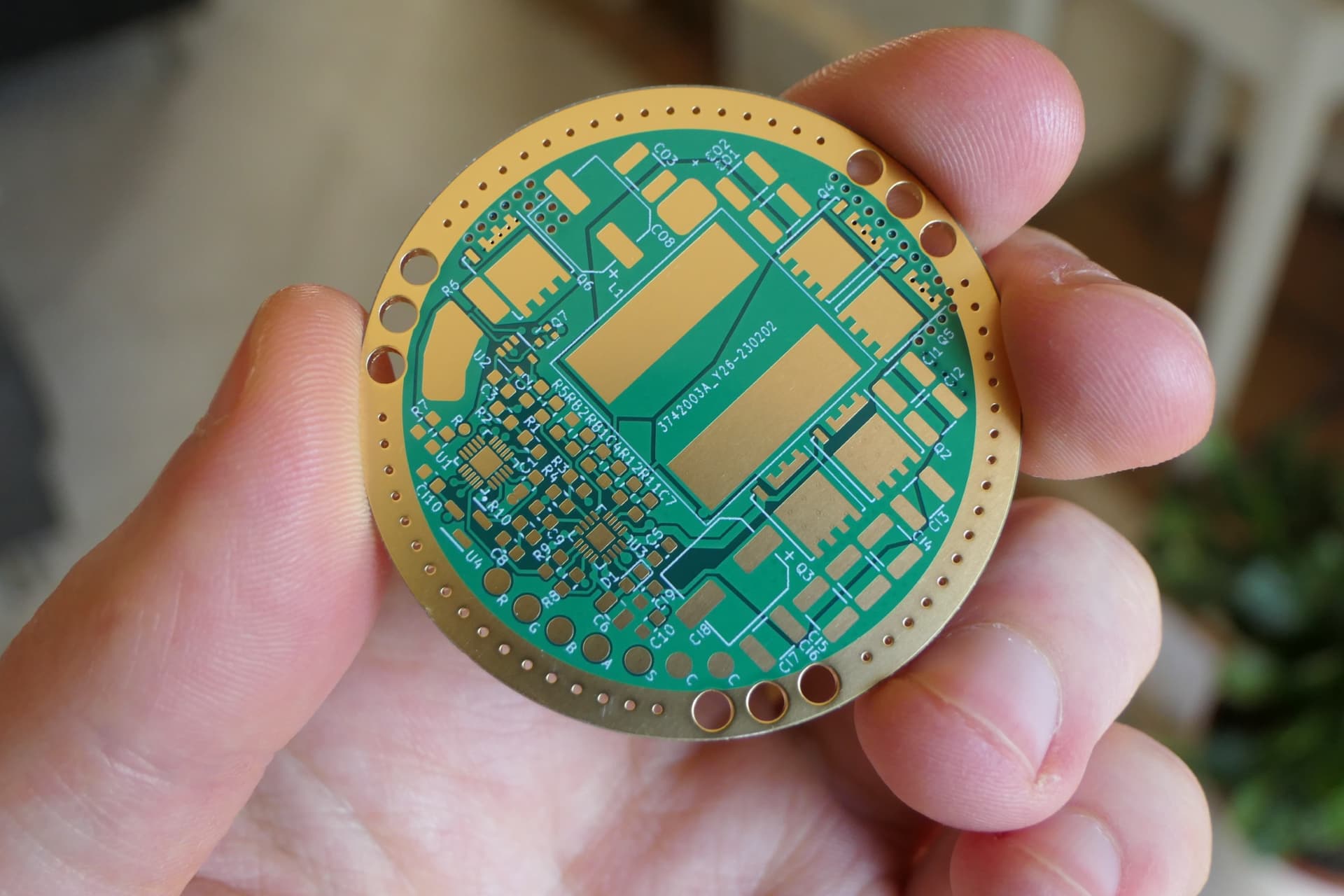
I ordered the boards from JLCPCB because they had a good promo on their high end 4/6/8layer boards, which I received 2 weeks later (pretty fast!)
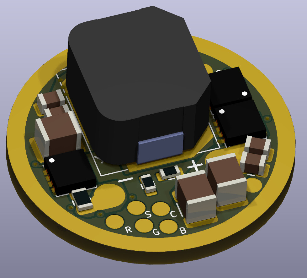
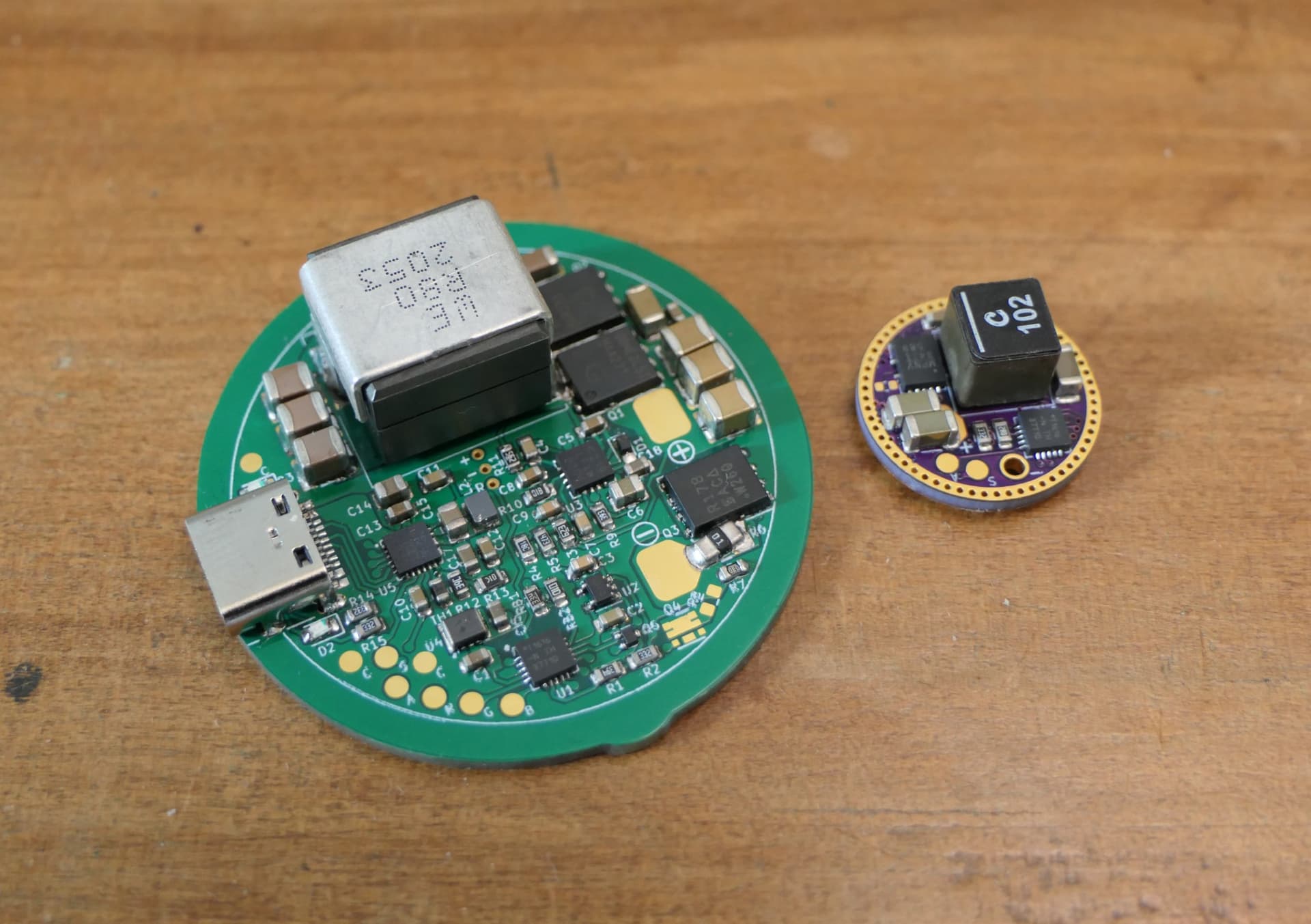
Assembled :
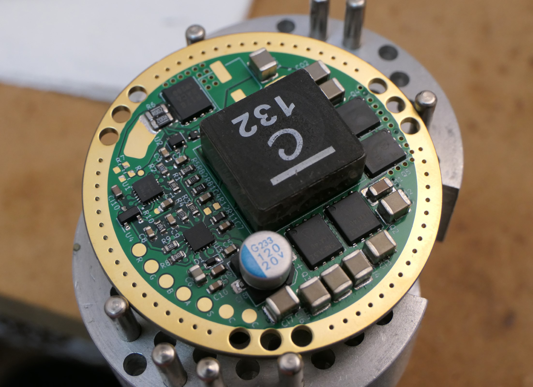
Testing :
For now I have only done a precise efficiency measurement at 10A because my lowest resistance curent shunt is 5mΩ 1W which is only good up to 14A.
11.764Vin, 5.811Ain, 6.903Vout (2P XHP50), 9.642Aout, efficiency=97.4%, LTPowercad simulation was 97.2%.
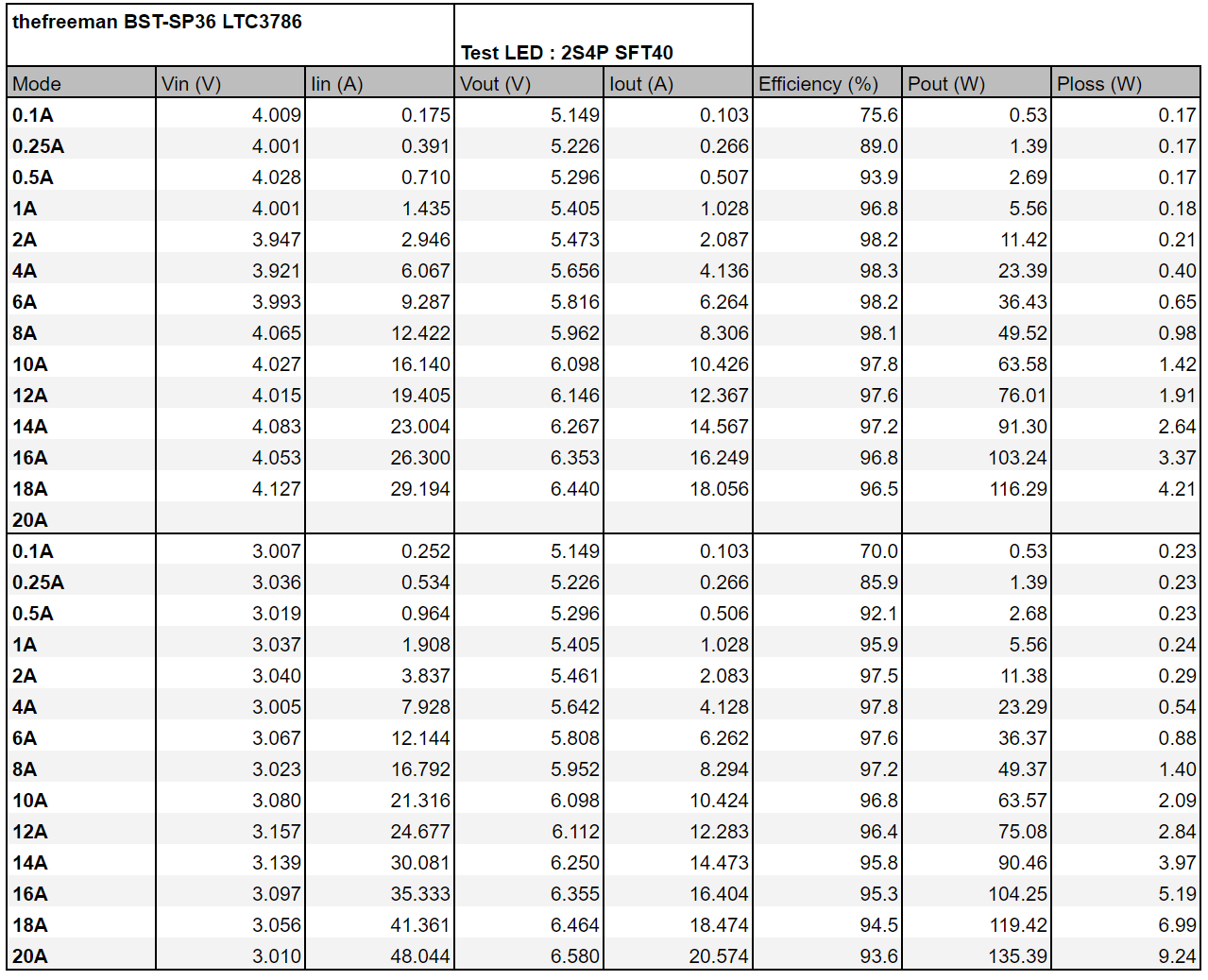
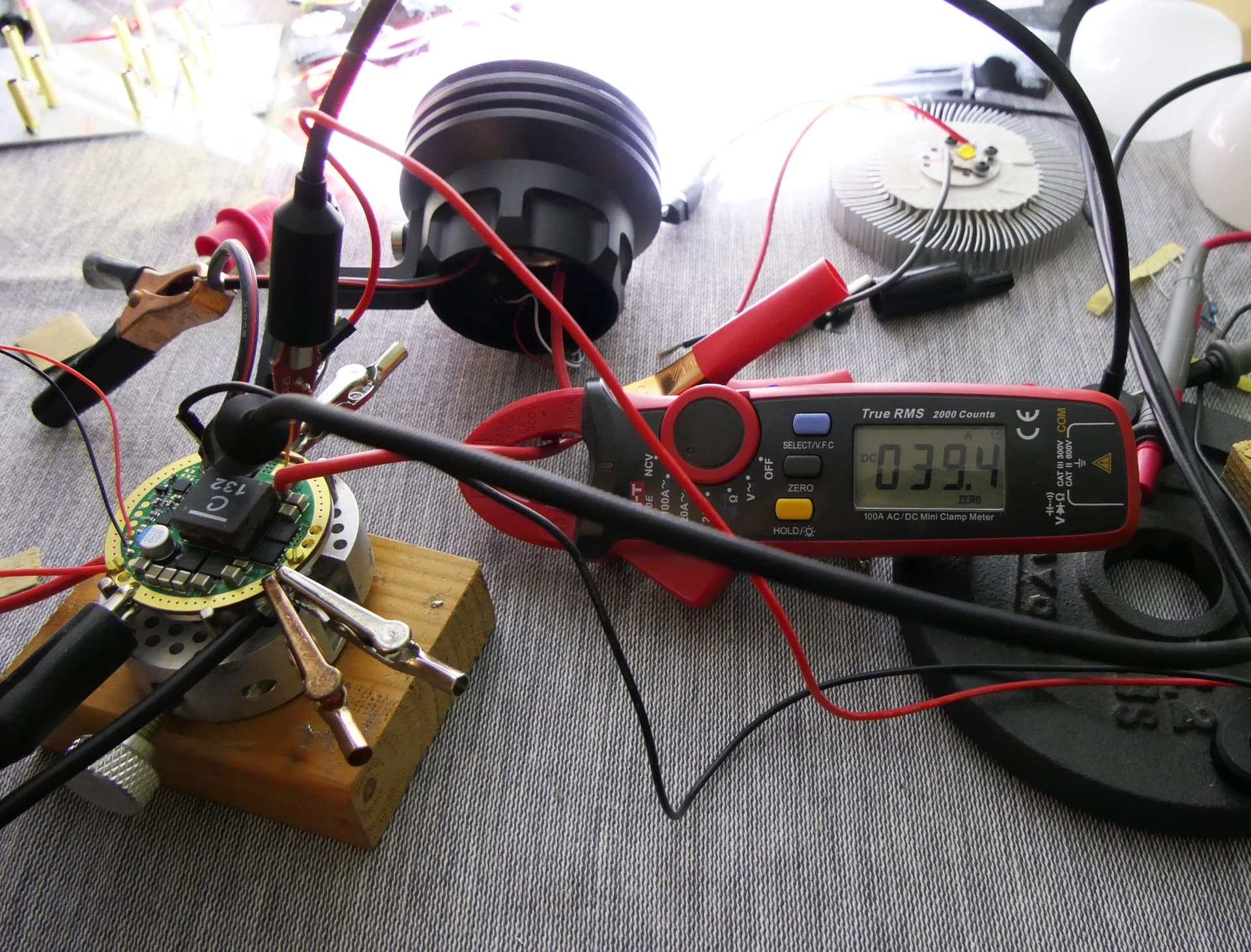
And a quick measurement with the current clamp at full power :
12.117Vin, 24.5Ain, 7.390Vout (2S4P SFT40), 39.4Aout : efficiency=98%, which again is about the same as simulated.
Next I’ll try to push it to higher output current, I need a better test load though, @haukkeli sent me XHP70.2s for that but I haven’t received them yet.
I’ll order 2 and 1mΩ precision current shunt for more accurate efficiency measurements above 14A, also I’m mising some components for low modes.