I don’t like the SC1 Plus because it will charge at up to 3A with any cell, while I want to do a 1A charge routinely and only charge higher if I need a battery urgently. Yes, I know, I could bring a weaker charger, but if I’m travelling light then I bring a compact 100 or 140W PD charger and carrying another low power one is an extra thing to need to bring.
Interesting and good to know about the charging ICs, definitely not something I know much about, I guess I’d just want a high quality choice used and not mind paying a bit extra for that.
I’m with you there - my usual travel setup is an Aukey PA-B4 65W GaN Charger used for everything.
I’ll try reading more into the offers of various chip makers, trying to see if I can find a fully software set-up-able. In theory you could even run user-defined programs instead of my current presets with some firmware editing - but I’m not sure if I’m not in over my head with software development at that point…
Was considering a small OLED screen, but since those are pretty much impossible to implement well in a cheap, 3d printable and robust housing, I’ll stick with an LED Interface.
Too bad, it would have been a unique selling point.
Then I can also use any commercial single-bay charger, which at least sometimes also have a display and a sliding mechanism which eliminates the need for an adapter. In the end, it’s the same thing. What should be the unique selling point here, apart from the fact that it is supposed to be open source (a fact that should not play a role for 95% of all people, as sad as that may be)? In a travel charger, 3 Amps charge current is not important for me. An informative screen would be great, especially if this thing should be used as power bank.
You’ve mentioned you work with nRFs, is that the plan for this too? That way the more UI-heavy features could be made accessible over bluetooth with the charger remaining compact and usable in simple mode without the need for a second device (like… without fancy charge progress graphs and whatnot but full functionality should still be doable on-device). Web bluetooth makes multi-platform BT config apps much more feasible.
Or… SK6805 LEDs come in 1515 format as used int the MicroMatrix
I’m way too stupid to do any software development on such a complex platform… I’m entry level in C, so I can do all the basic stuff, but once I have to deal with complex hardware features (even if I have a HAL to abstract it) I’m completely lost. Even clicking together a simple webui to control a few motors in Arduino on an esp32 took me a long time.
So, unless anyone here is a good embedded C dev and willing to dig into the SW side for me - no.
Also, I’m not willing to add 8-10$ to the BOM of a charger (that’s like, double the BOM or more…) just to get cellphone controls…
My aim was to have a header file that controls the profiles, and have easy flashing over USB, so people can change the major variables, recompile and flash a new FW easily.
And maybe I’ll just add pads on the PCB for a small OLED just in case somebody wants to add it eventually. Modularity is king.
I like the led matrix thing - already designed a 12x12 monochrome led dotmatrix for another project but sadly never made it happen. Dotmatrices are gorgeous to look at.
For sure, it’s an idea for a place to offload features that would warrant an OLED but keeping things simple is always preferable for something that’s meant to be used out there in the field.
Yeah, essentially I want a charger I can toss in my backback, carry around wherever I’ll go, and not worry about a few scratches, and ideally even losing it won’t hurt too much
I’ll definitely take care of proper ESD-proofing of all exposed connectors, so it won’t be zapped in a bag, and I want to make the case both sturdy and easy to replace (if you own a 3d printer to make a new one, that is) if it ends up beat-up.
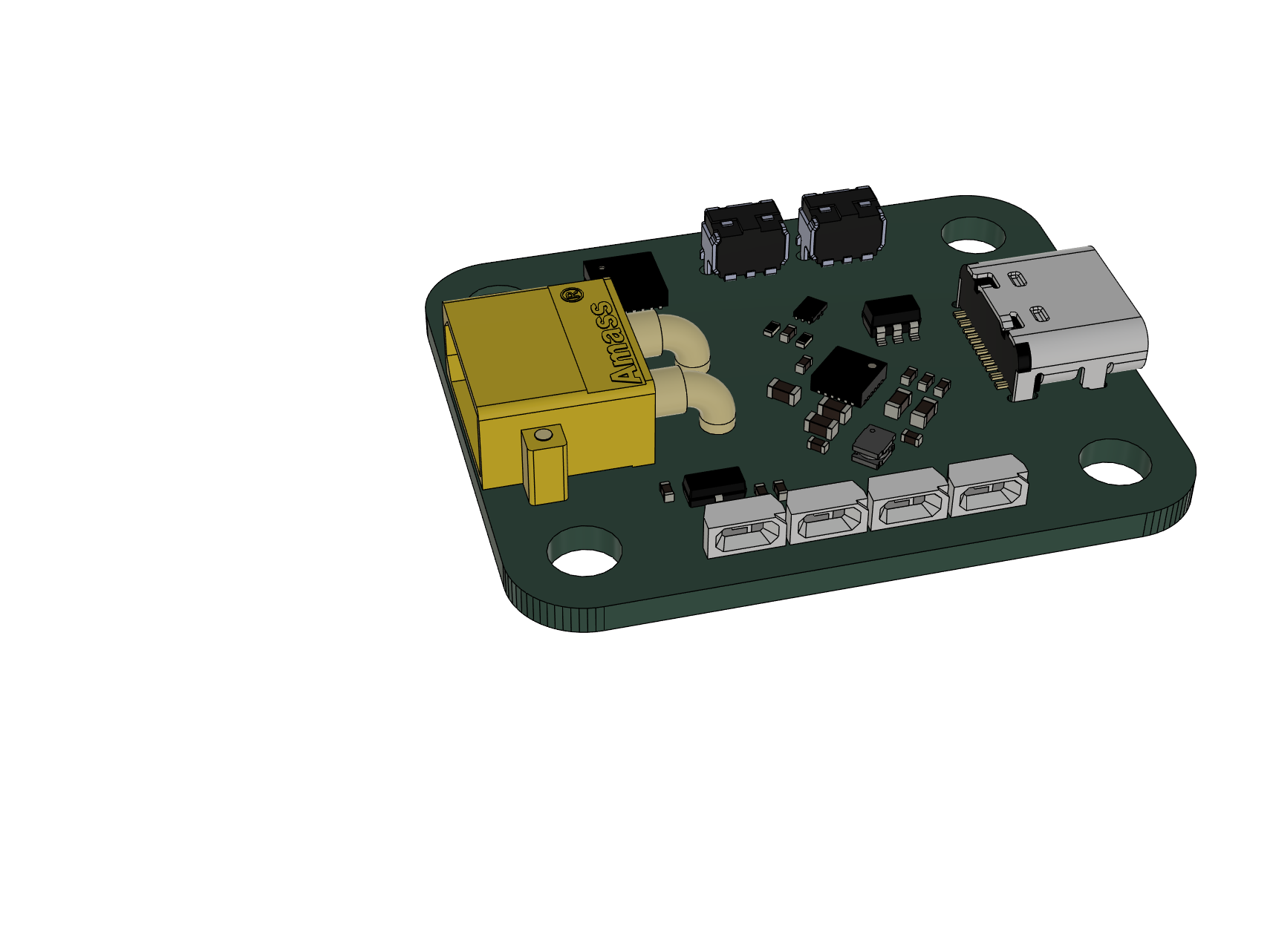
So, I spent some time tinkering. This is my current status.
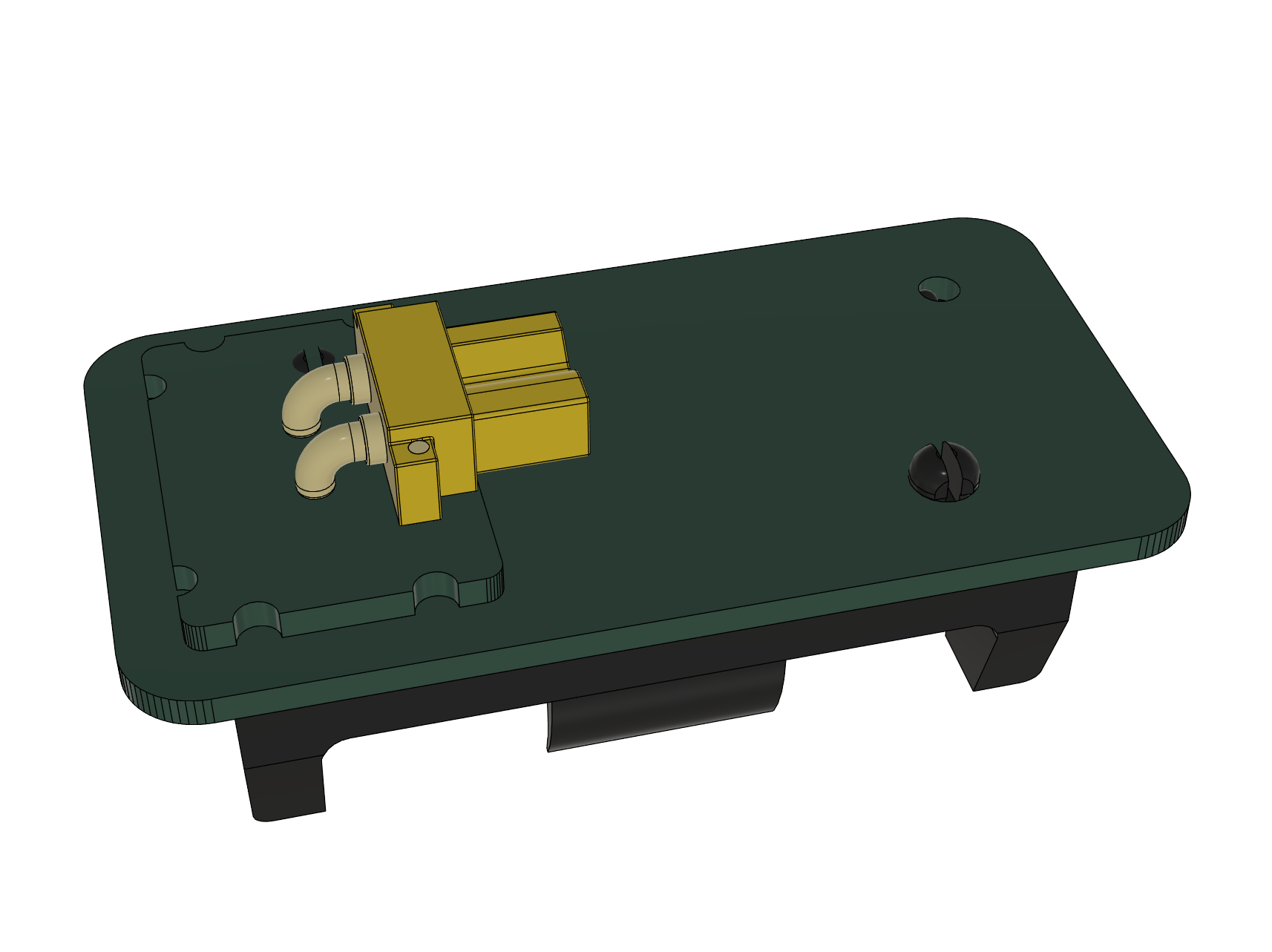
The charger now consists of a core that is the full charger. The battery holder is connected via an Amass XT30PW connector, and a tiny daughterboard soldered to the battery board as a spacer.
The current model is made for a 18350 charger, as that is the smallest formfactor I consider. 14500 is longer, and everything else is obviously longer. This allows for a single “core” charger that can be used with various battery holders, from 14500, over 18350, 18650, 21700, and in theory even larger. Additional “battery modules” are cheap to make as they need no SMD assembly - 2$ PCBs from jlcpcb, 1$ connector and 2$ battery holder is all you need to add a different cell type to your lineup.
The connector also makes it a very flexible design since somebody could develop a 3d printed spring loaded holder, or once I figure out how to make proper magnetic leads, that can be connected to the core as well.
I also upped to 2 buttons and 4 RGB LEDs and I am still trying to figure out if I can somehow add an optional OLED to this thing, but PCB component density is already annoying
Don’t mind the snap-in pins of the battery holder that clip into stuff - I will not use this particular keystone holder with snap-ins for the final design. They are just here since I found decent 3d models for them.
What’s your opinion on this design? I tried to take most of the feedback so far into account (incl @wolfgirl42 and her need for chonky cells) Any more recommendations/suggestions/criticism? In the first “wave” of protos I will only have 5 cores and 5 18350 modules made. If everything works well on those, I will add larger sized modules, and publish the PCB sources. But tbh, I am still pretty far from a functional prototype. Size will mostly stay roughly the same, but I still have to add:
Route the entire MCU
Figure if the OLED fits
If yes, add and route it
If no, see if I can at least add pads somewhere so one could hand-wire the OLED with airwires and find a way to mount it to the case
Add reverse polarity protection to make it safer to use
Route the current-setting resistors for the charging chip
Add the temperature sensor
Do lots and lots of sanity checks
EDIT: Not fun, but I should be able to squeeze one of these in: 1.36€ 28% OFF|0.66
Reverse battery protection is now added as well. Insert the wrong way round = nothing happens.
May replace the FET with a beefier type with lower R_ds,on at a later point.
My head is spinning, I’ll head to bed. Good night!
Oh, if I understood the datasheet correctly - if you want to use anything but the default 500 mA you gotta add the battery first, set the desired charge current, and then plug it into USB, otherwise it will charge with default current only and won’t be possible to change. Also, if you wish to change charge current you have to unplug and replug. So basically, current changes can only be made while the charger is only battery powered and not USB. Bit of a weird limitation… I might be wrong though. The datasheet is not really helpful in that regard. Prototypes will tell.
I can’t see any workaround with the chip I am using, and I did not find any decently specced and sufficiently small alternative for this chip either. Hope that’s not too much of a hassle to use.
On the up side: If you want to use anything but 500 mA as a default, you can make an adapted firmware, flash it, and then it will default to whatever you set.
If you set it up to 3A, but plug into a cheapo 500 mA USB supply, the charger will correctly limit itself to that. It can detect pretty much any fastcharge protocol in existence, and limit output power accordingly so it will work in all circumstances without overloading the power supply. Main reason why I picked that chip.
I ended up sticking with the MAX77757 in the end, since I could not find anything with a comparable festureset that fits this PCB… Some people got it to work, so… Hoping it’ll work on my PCB too
I’d love to use one of the bigger (feature wise) maxim chips with i2c, but those all come in some annoying BGA packages, and I’d like to stick with stuff I can put on a 2 layer PCB.
ok, a cheap alternative stocked by LCSC/JLC for JLC assembly could be IP5189T
2A charging and discharging, output is a separate port so no need to handle sink/source negotiation, no USB-C CC support, only " Apple, Samsung and BC1.2 interface’s D+ D- specification", CC pins would have 5.1k pulldown to force it as sink with a type C connector.
Current is resistor set, so you’ll have a resistor for each current setting wired to a MCU pin.
Injoinic also has PD3.0 charger ICs, except the current is not adjustable which is just weird.