Nearly a month since I have updated it. ![]()
Next weekend will be the third weekend in a row that I wont be home for most of it. Soon. Soon I hope I can update this thread. ![]()
Nearly a month since I have updated it. ![]()
Next weekend will be the third weekend in a row that I wont be home for most of it. Soon. Soon I hope I can update this thread. ![]()
Plenty of popcorn left, so for me there’s no need to rush ![]()
Was wondering where you’d been, hope all is brillig in the wabe.
I have hard enough time understanding English let alone Jabberwocky. ![]()
I’m playing with one of these again this coming weekend.
https://www.google.com.au/search?q=1928+avance+tractor&rlz=1C1CHMO_enAU566AU586&espv=2&biw=1084&bih=961&source=lnms&tbm=isch&sa=X&ved=0ahUKEwipltrQvPnOAhXGKJQKHZhnDK4Q_AUIBigB
Will I see you there?
Only if I can get free of the slithy toves. Have fun, it looks like it should be a gas. Snicker.
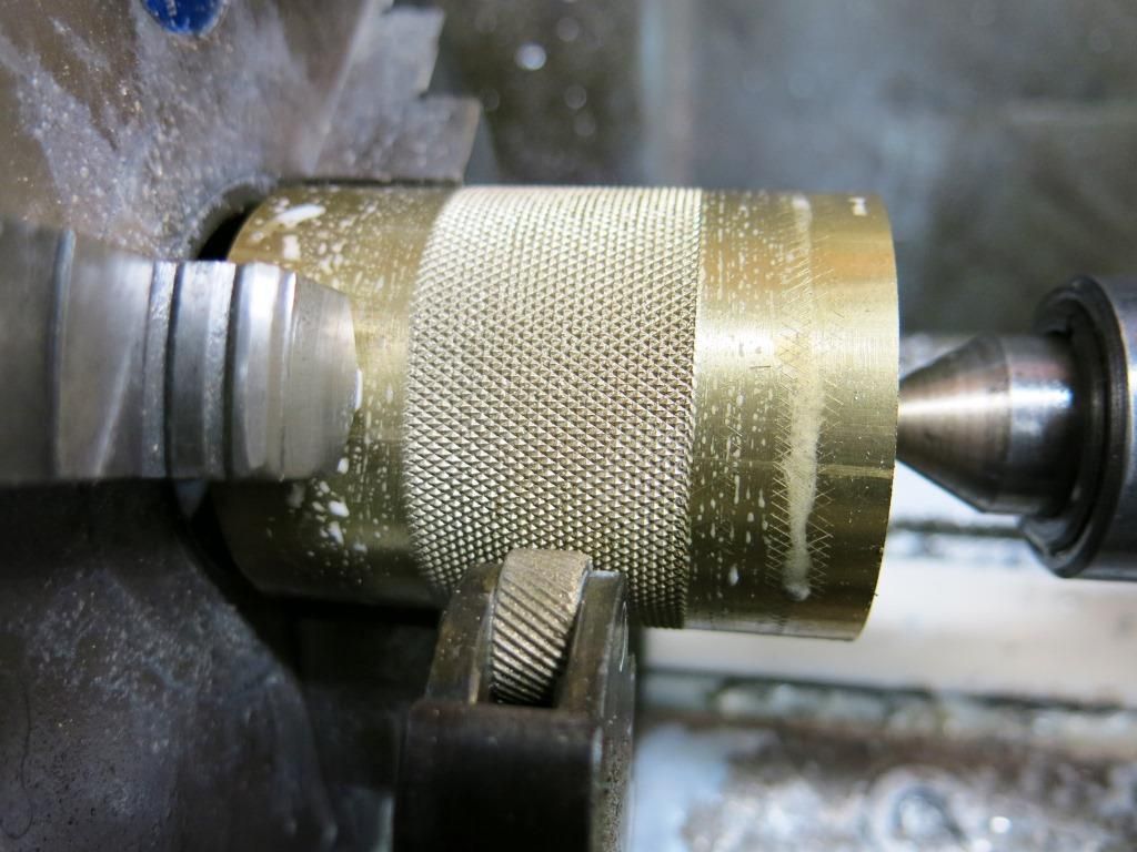
1.10.16.
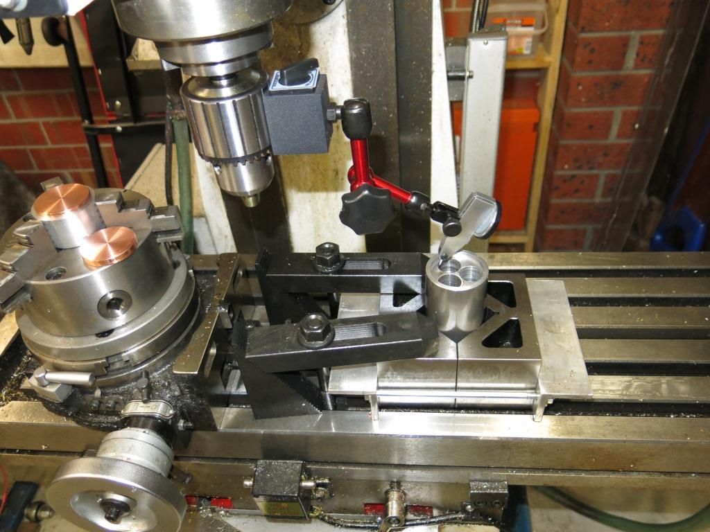
The OL comp light is finished and the dial test indicator has arrived so I’m back onto these lights.
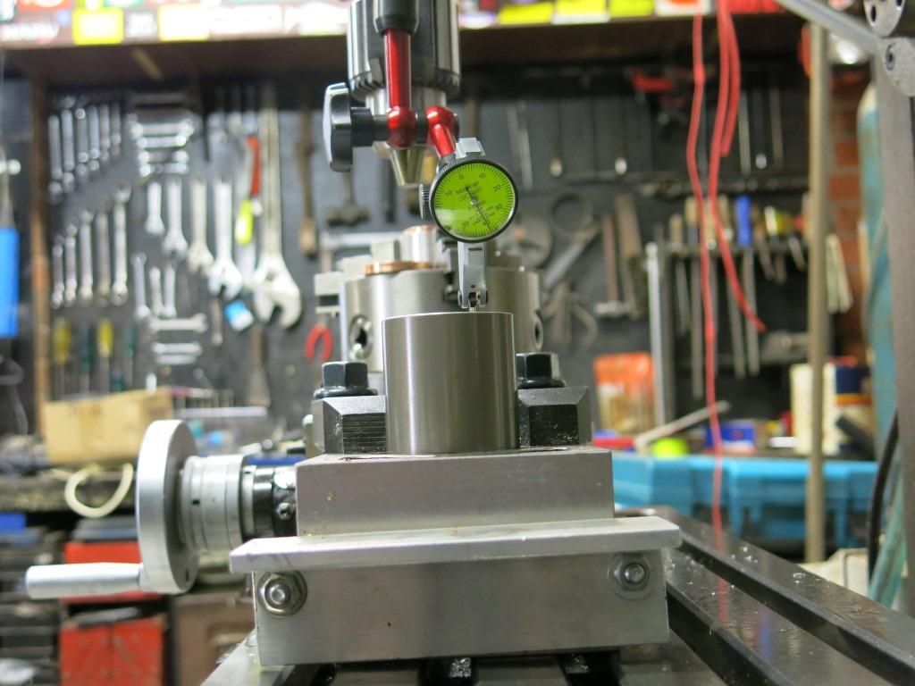
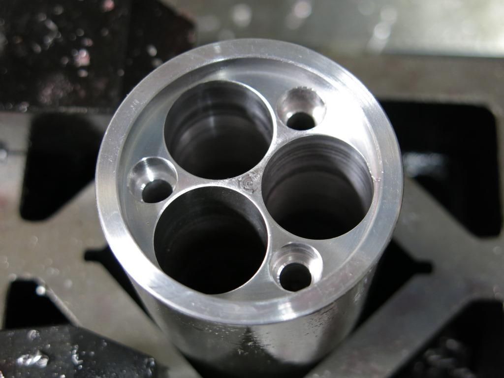
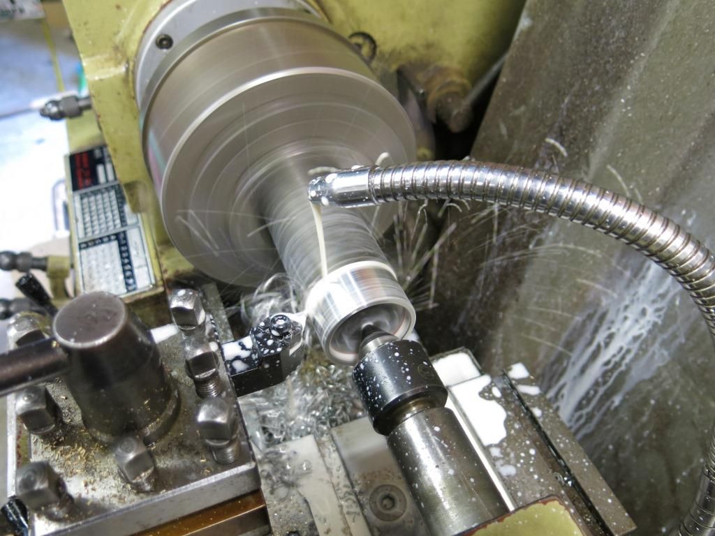
When I left of last time I was having trouble setting up the battery tube square on the bed of the mill. The dial test indicator has made this setting up a walk in the park as shown in the next couple of pictures.
With the bed in the one position on the x axis I only have to turn the battery tube until I get the same reading on the dial from one battery hole to the next.
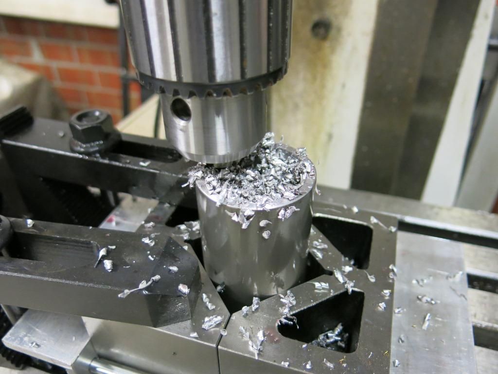
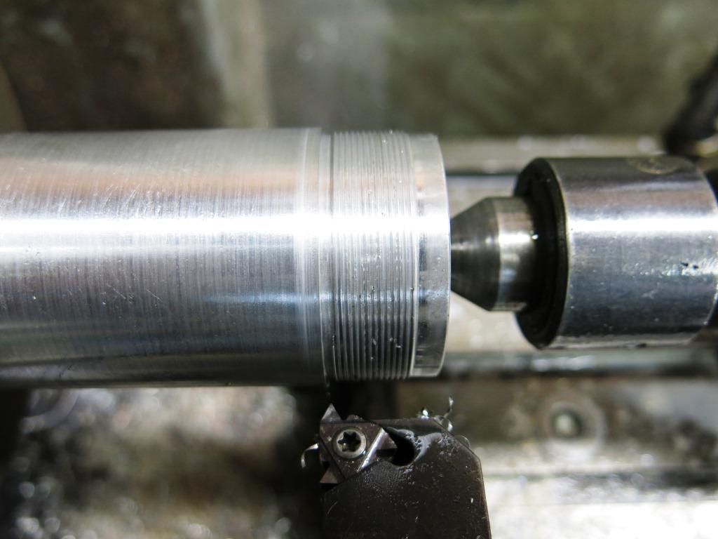
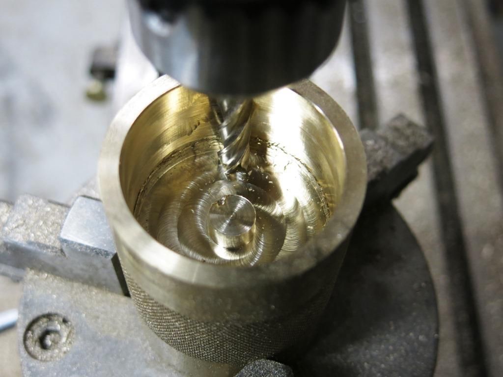
A 13/64’’ drill bit was used to drill a hole as deep as it would go (65mm) in three places around the battery tube. These are the through holes for the cap screws that will bolt the two battery tubes together. This is a style that OL uses to attach different items together instead of threads.
The three holes completed.
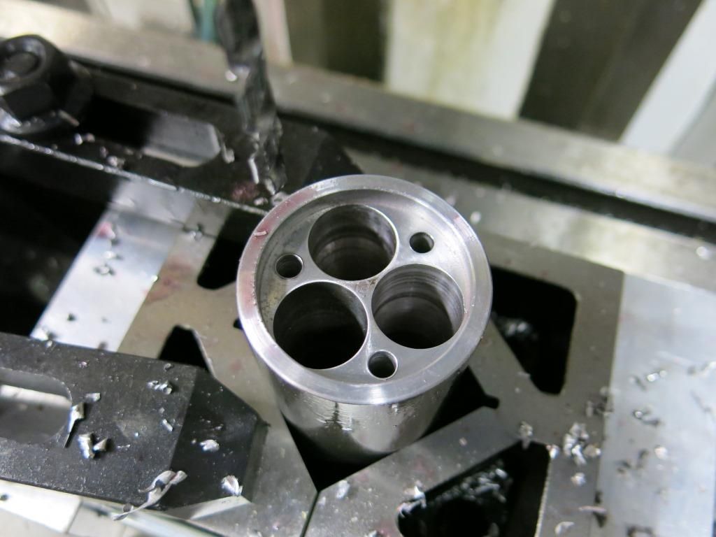
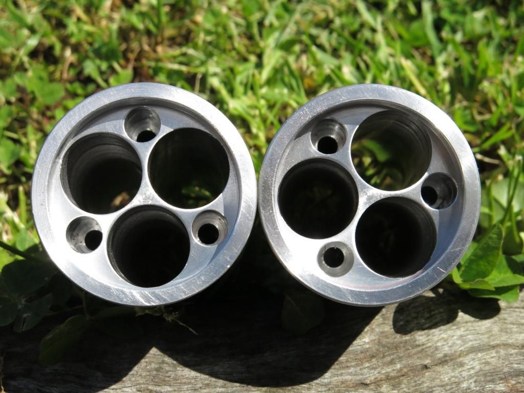
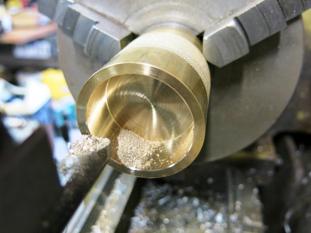
These holes are then enlarged to 5/16’’ to allow the heads of the cap screws to sit below the surface. After l had finished I realised that I’d forgotten that these holes are also used for the locating dowels on the earth plate to stop it turning when the tailcap is screwed on. The battery tubes were put back in the chuck and the holes deepened to 20mm. Silly me. :person_facepalming: I must just like making work for myself.
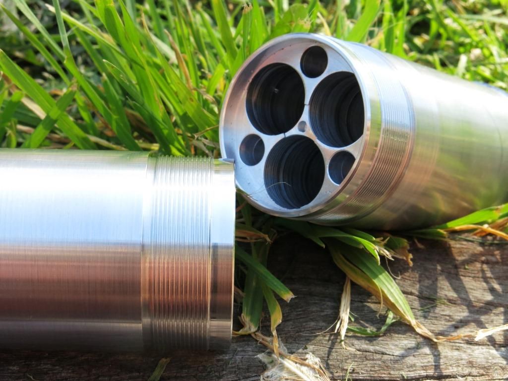
Heres a shot of the holes in both battery tubes at the correct depth.
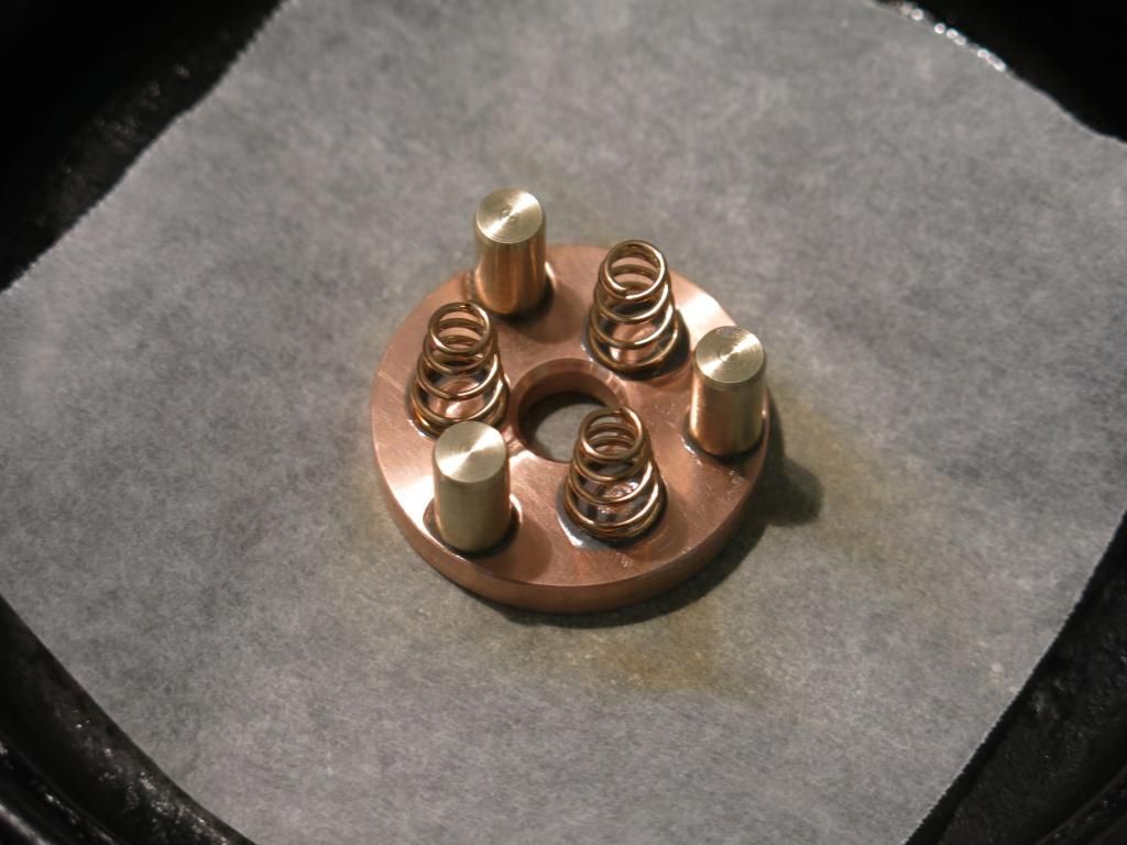
Two more (I’d already made two that would never work) plates for the locating dowels and springs to be attached to were machined up. The holes for the dowels are 1/4’’ and the spot faces for the djozz springs are 10mm (sorry for the metric and imperial measurements).
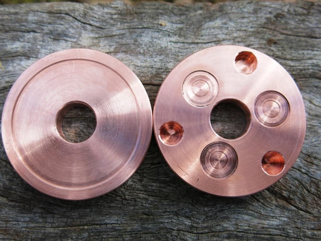
The plates along with the new dowels and djozz springs awaiting to be soldered into one piece. The dowels are 7.5mm in diameter giving around .5mm clearance on the holes in the battery tubes.
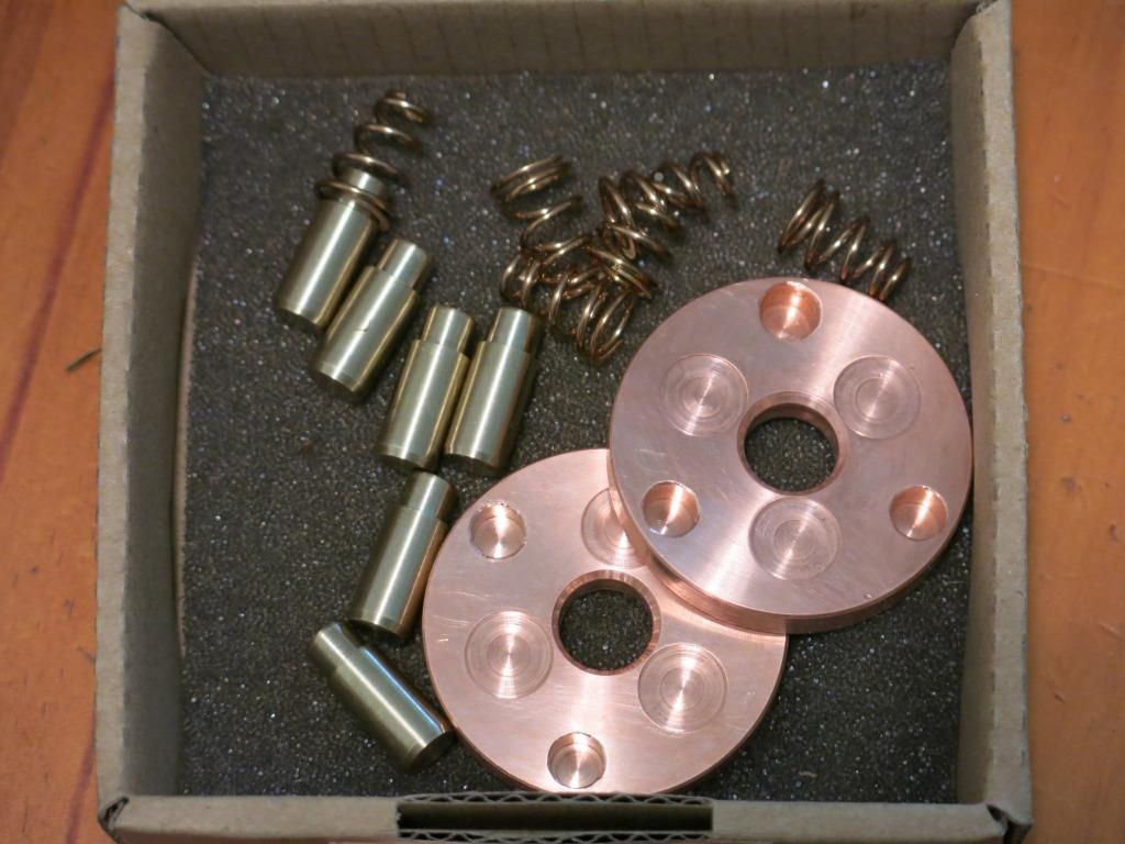
The soldering oven, well hot plate set to a temp of around 250 degreesC (the wifes at work ![]() ) with the parts heating up.
) with the parts heating up.
And doe’s it all fit together?
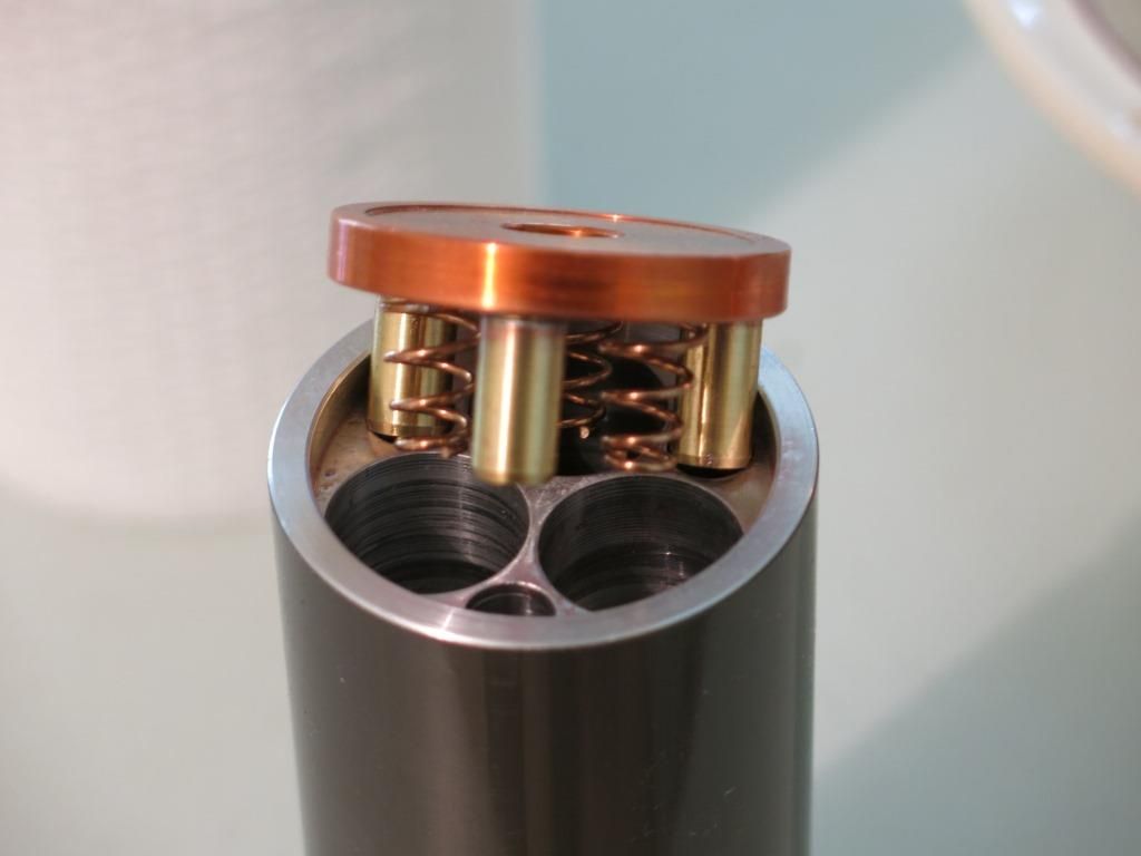
Yes. ![]()
After lots of PM’s with Richard it was decided that the driver required was not going to happen without reinventing the wheel so I revisited the original driver I tested.
To be honest I did not do the driver justice originally as after removing as much resistance as possible from the test the driver had the XHP 70 cooking at over ten amps.
I have two more of these drivers on order which should be here soon.
What this means now is that it will run on 2S3P battery set up and not the 3S3P setup as originally planned.
The second battery tube will be considerably shorter than planned.
That’s it until the next update, thanks for reading.
Nice work. Now I want a lathe ……
As usual, superb. Think you might be a machinist by trade. Hobbyist aren’t that good.
You are one funny guy southland. ![]()
I’m just glad I can get back into building the light.
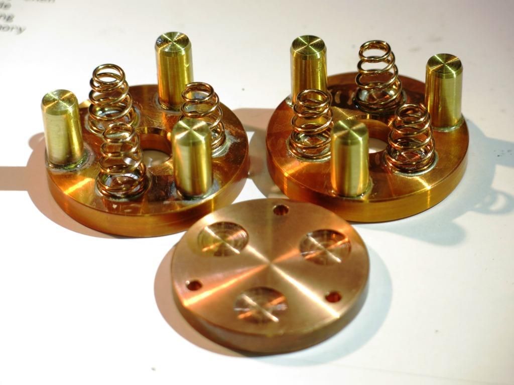
Heres a picture of the completed plates with one from the first effort out the front. The outside diameter is 42mm and 6mm in width. It is large, chunky and hopefully be held captive to the tailcap.
Cool beans!
Nice progress! ![]()
Very Nice!
Looking really good there!
Super nice clean work Steve. All those little parts are the pits to turn out aren’t they. They get tiresome after the first three or so.
Really nice!!! TL
It could of been TL but I’ve had a break from it for awhile and I do love why these are getting made.
Thanks for the comments guys. Any suggestions are more than welcome.
You’re a good egg Steve. I love why you are making them too. Suggestions…. well, when parts look like that, suggestions are tough! That is as clean of work as anyone on earth could ever ask for!! ![]() :+1:
:+1: ![]() TL
TL
Update 12.10.16.
The threads for the tailcap on the battery tube were machined next. The OD of the thread is 46.5mm.
This picture is turning the OD of the battery tube down to size and machining the oring groove.
The thread in its raw form. Pitch is my usual 1mm.
And the finished threads.
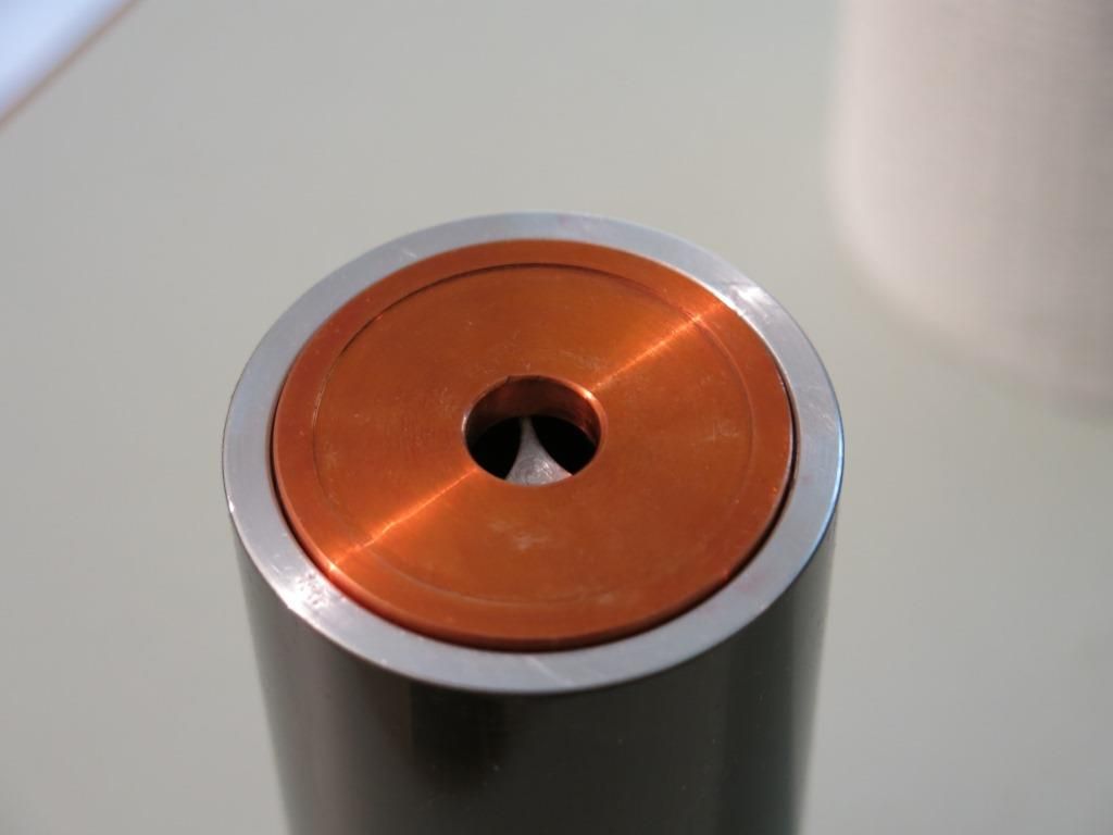
Knowing the thread on the battery tube, I could now draw up the tailcap. The spigot in the centre is what the copper negative plate will rotate on. It will be threaded 6mm and the plate held captive with a taper head cap screw.
The two tailcaps will be machined from one piece. I’m not sure of the outside look as yet but knurling had to be in the picture somewhere.
The inside was machined to the depth of the spigot here.
The tailcap spigots were then machined in the mill. The rotary table is 90 revolutions of the handle to one turn of the table.

2160 turns later we have two spigots roughed out. The tailcaps will internally be finish machined in the lathe next.
Nice Steve!!! Most of yesterday I was covered in chips! But I still super enjoy looking at your machining images. What a light this is going to be. The quality of work is just stunning!
More! More!!! :+1: TL
I have very little to add as I have none of the experience of most of those commenting here. This may come across as ignorant, but when looking at the pics of the dowel’s and battery tubes the first thing that came to mind was a revolver chamber and bullets. ![]()
PS. Beautiful work.
The first time I looked at those images, that was my thought too…. looks like my Ruger 41 Mag!!! ![]() TL
TL