Yes, very easy. Loosen 2 screws, remove the back, turn it on, hook up the leads, get your little screw driver and turn the “adjuster thing” very slowly till it reads correct.
I then turn it off & on again, recheck, & if all is still good. … put it back together.
That’s it.
~
~ EDIT: … “adjuster thing” = potentiometer
No. I wish it was UT61E, because that one is pretty easy to calibrate.
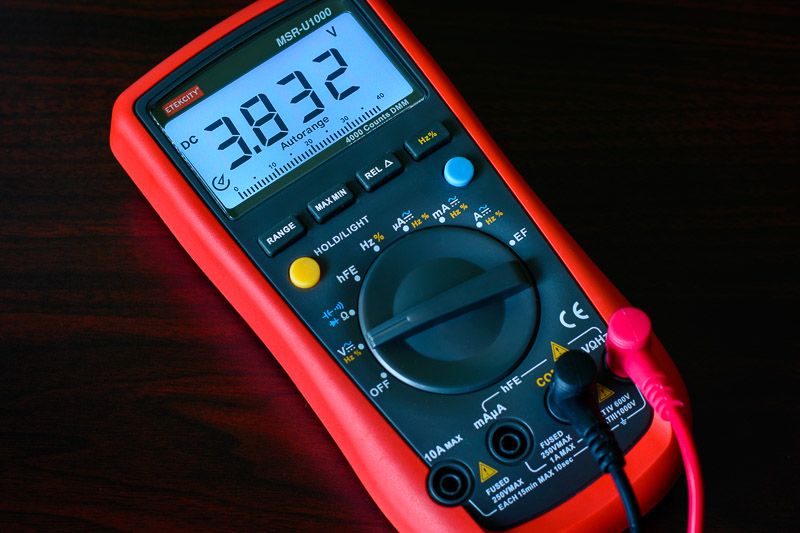
What I have is Etekcity MSR-U1000 which is a rebranded Uni-T UT61A. This one has multiple potentiometers that could potentially be used for calibration, but so far I have not been able to figure out which one does what and how they interact together, and because the error is pretty small, I decided not to mess with it. Plus, I’m not 100% sure that my voltage reference boards are dead-on accurate either.
FYI, according to my KKMOON rig (based on AD584LH board), the above Etekcity DMM reads low by about 0.22% give or take, so again, not a big deal for me.
Yeah it is Venom, to be honest I was quite pleasantly surprised.
This one has not been babied at all, I’ve used it on cars, boats, lawn mowers, you name it… plus it has been dropped and mishandled numerous times thru the years. :person_facepalming:
Yup. Someone gave me a link to a technical doc on this DMM, but it was way over my head, so I decided that if it ain’t broke (too badly), don’t fix it.
Yeah that is pretty small Pete, 6/1000th’s. Close enough for ‘gooberment work’…….
I like that “case” your VRM is in too……… :+1:
~
Now, if you don’t mind; I have a question for you about you picture below…….
Below the Voltage readout & below where it says “Autorange” there is a group of short vertical lines numbered 0 to 40. It appears as a “horizontal graph” that is reading “38”.
What does that represent or tell you/us
The VC99 is the first DMM I have ever owned that had those.
I have no earthly idea what they represent & if it tells in the “manual”… I can’t find it.
.
Yes, it is certainly within the accuracy range quoted by the manufacturer (+/- 0.5%).
Good question. The owner’s manual does not go into detail about this bar graph. I think it is meant to graphically represent where within the currently chosen measuring range your reading falls. So for example, in that photo, the DMM is in the 4V range, and since the reading is 3.832V, the bar graph illustrates that you are near the upper limit of this range. If your reading was to go above 4V, say 4.1V, the DMM would shift to the next available range (up to 40V), and the bar graph would then illustrate that you are at the lower end of that range.
But those 0, 10, 20, 30, 40 numbers on the bar graph scale are static, regardless of which range you are in, so that is kind of confusing.
Thanks for explaining this. I haven’t really paid attention to how quickly the bar graph updates. I typically check battery voltages with it, where there isn’t much if any rapid fluctuation.
That’s because your DMM is 6,000 count, I presume, which means you get 3 decimal points resolution all the way up to 6V.
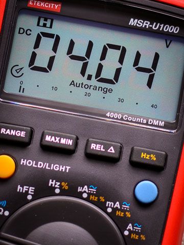
In comparison, mine is only 4,000 count. So I only get 3 decimal points resolution up to 4V. Once the measured value is above 4V, mine drops to 2 decimal points, as you can see in the last photo I posted.
OH…. OK…… I understand that. :+1:
That is why mine drops to two decimal places on the 7.50 Volt reading. I had been wondering about that.
Thanks for explaining that Pete.
—
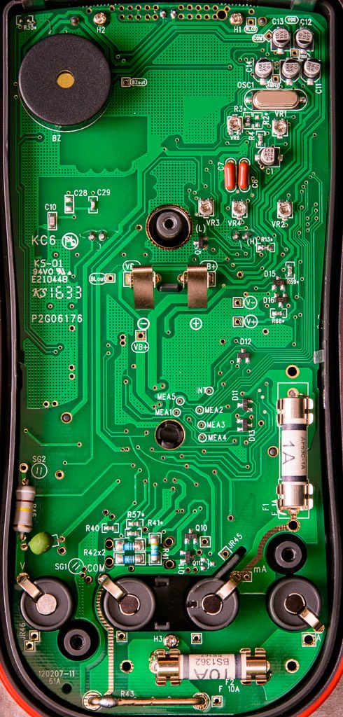
@ Pete7874 The picture of the meter in post 153. Are the glass tube looking fuse the same one that are used in automotive, if not are they hard to come by?
@ teacher Is there any way to test these voltage boards? For the battery operated voltage boards, when the battery voltage drops will affect the voltage board accuracy?
I know this was for teacher, but I’ll chime in with what I know.
You basically take a measurement with a known calibrated highly accurate DMM, and write down the result. That is the actual voltage being put out, and you can then see how your own DMM compares. That is why the one I posted above has that little sticker with actual measured values from an Agilent DMM written down. Granted, you put your trust in that someone actually did these measurements on your board and not just copied the same sticker and plastered it on hundreds of these boards without actually measuring. These things are cheap, so you never know, unless you have another perfectly calibrated DMM sitting around to verify. That is why I wrote earlier that I don’t trust it 100%, but all my other cheap/free DMMs seem to indicate it’s correct.
As for the battery, most of these voltage boards have some kind of voltage regulation circuitry to keep output voltage the same, just as long as the battery voltage is above a certain level.