If you replace the driver spring with a brass button or a spring that collapse fully protected will fit
another for the time being fix, till new 18350 tube comes, is add a copper solid wire ring or washer in the tail cap, but then the O ring can get exposed
So I am in the final stage of getting the electronics sorted out
there are basically 2 options to go:
- The charging circuit works without the old MCU, but no status indicator LEDs as they are controlled with the MCU
- Letting the old MCU active but disconnecting the switch, the light shows proper charging indication and is always in the breathing mode draining 1mA from the cell down to 2.38V, when the MCU shuts down, physical lockout needed like lighted tailcap
I'd scrap the charger, least that's what I'm gonna do. More room then - I plan on adding some copper under the shelf, least it's some added mass. Probably use thermal glue to hold it to the shelf.
thought about it, but not about extending the shelf with a copper block from inside, you can easily double the heads thermal mass
yes adding some mass helps getting a longer turbo mode
The main issue with NarsilM is it does not support timed step down plus temperature, like v1.4 did, so I stick with v1.4
it is a lot easier to get it mechanical done scrapping the slave board with MCU and charger
Still can't figure why you would want both. Don't think I ever heard of any light using both. Are there? That's why I did away with it - could not figure a reason to have both active. Shame because there are bug fixes and enhancements in NarsilM.
I probably could get a compile switch in there to enable both modes somehow, just gotta figure out the UI for it the combined version. I got a ton of other things to do on NarsilM though, and haven't spent any time on it as of late at all.
The charger is one thing that I liked about this light. Being that it’s powerful and uses 18350 cells, I’d rather be able to charge it without waiting to get home and fire up the charger. I guess I’m stuck with the light as is.
driver replacing without keeping the chargin circuit is easy, a 21mm driver fits with minor sanding
with AWG18 and SIR800 FET pulling 18.9A on cold start
instead the 9.95A with fresh Samsung 18650-30Q cell
I went with a solution I like, keeping the old drivers slave board electronics with charging
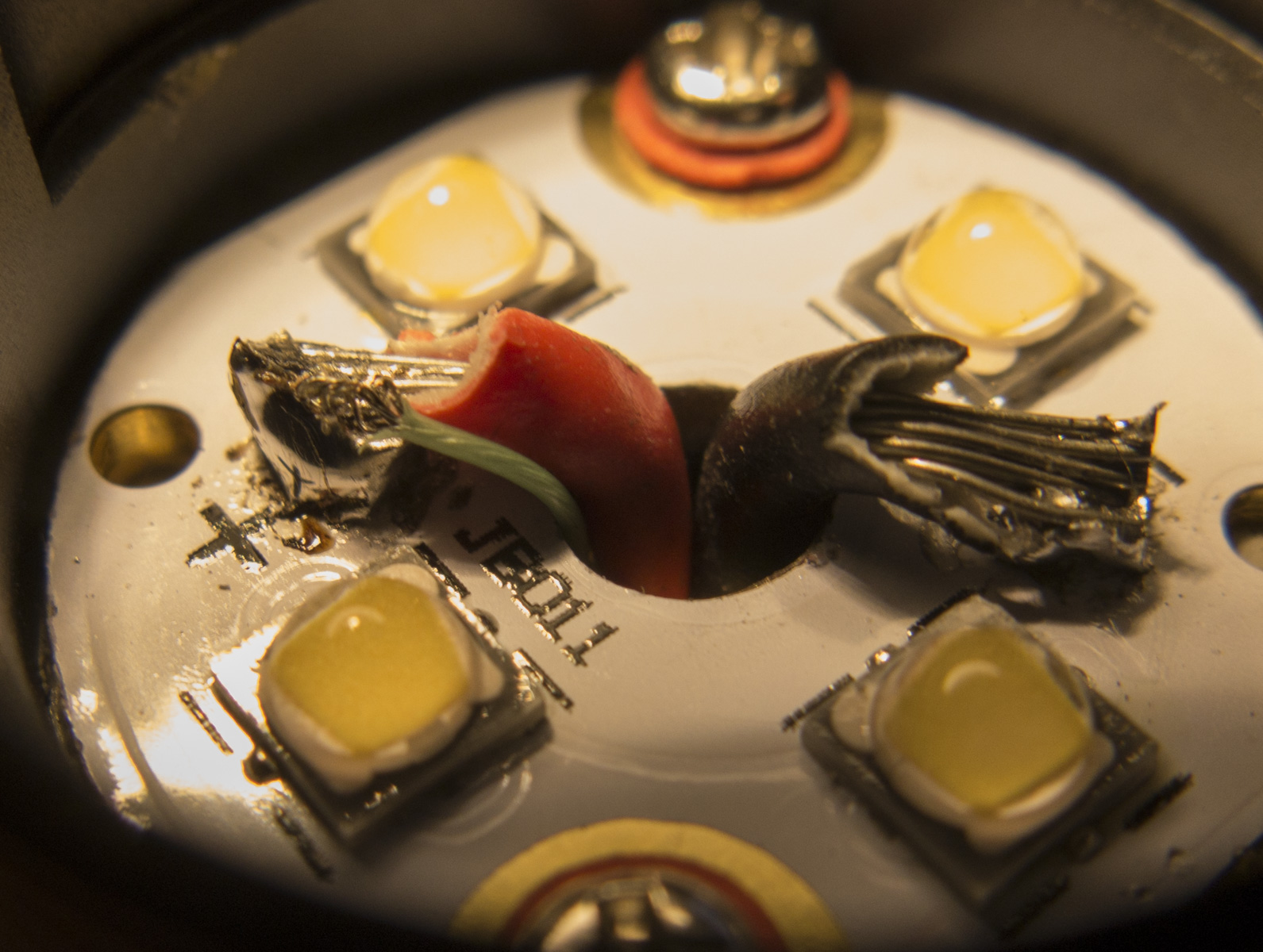
I did wire the old electronics with the LED+ wire on the star, so if I want deactivate the USB charger and breathing lighted sideswitch to get rid of the parasitic drain,
I can unsolder the thin wire on the star
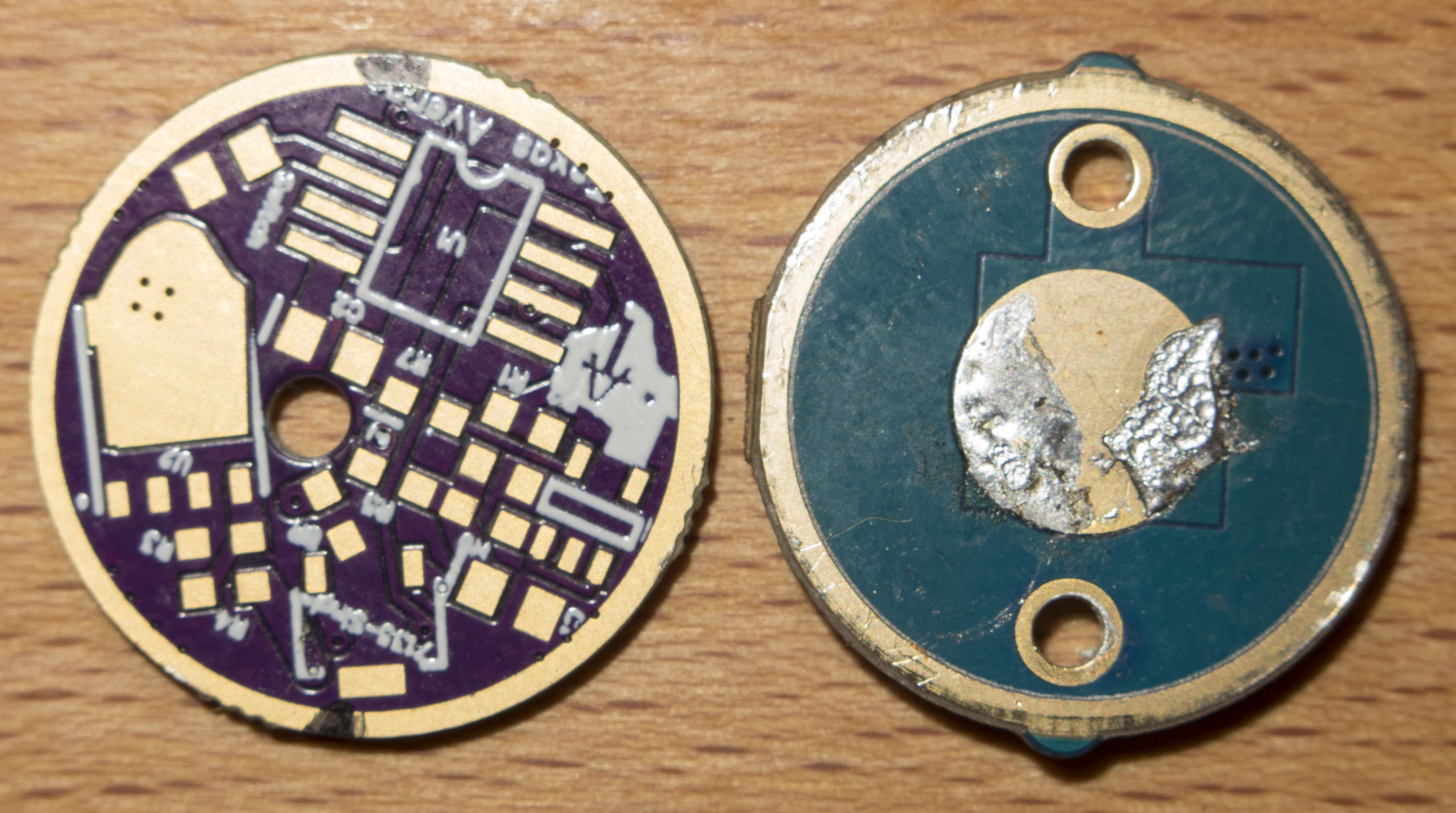
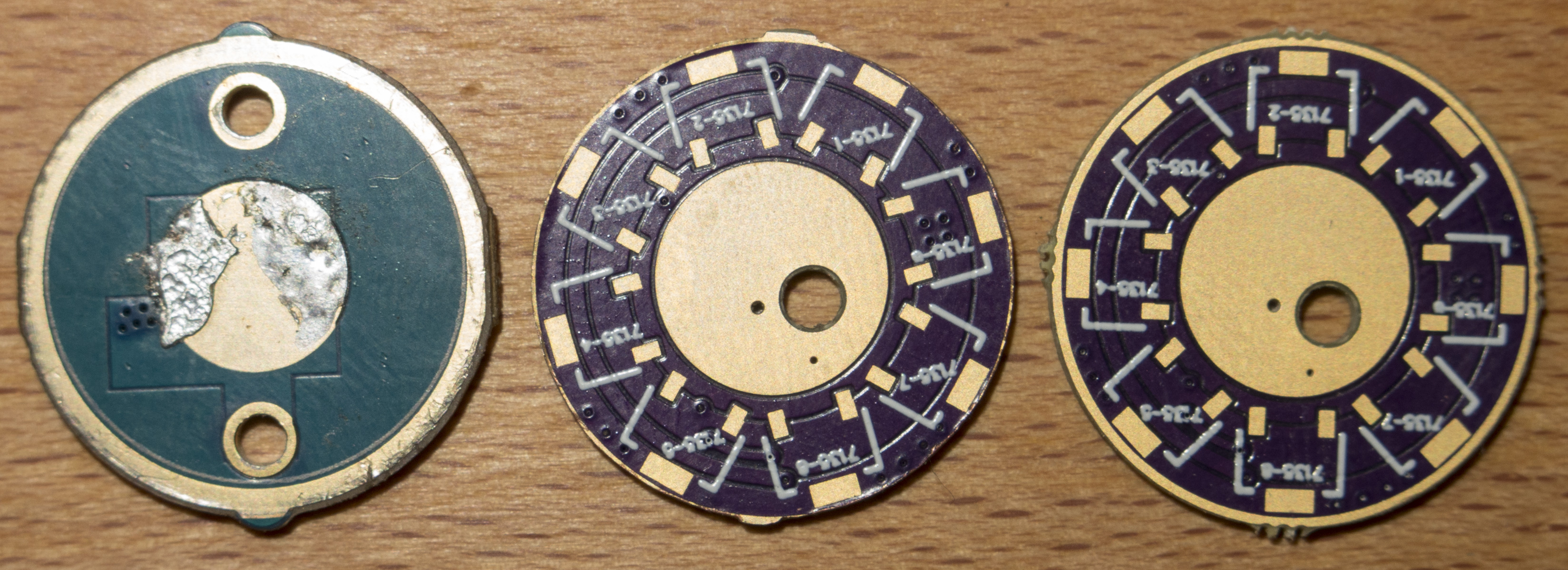
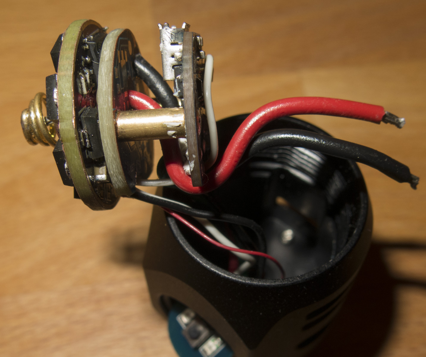
The drivers contact board and TA 21mm LDO driver
trimed the board to fit easily
used my Dremel to get rid of unsoldering the leads to the switch board
trimmed the old driver contact board to fit inside the head, cut the bolts connecting both boards by 4mm and sanded it
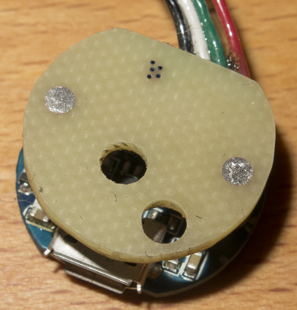
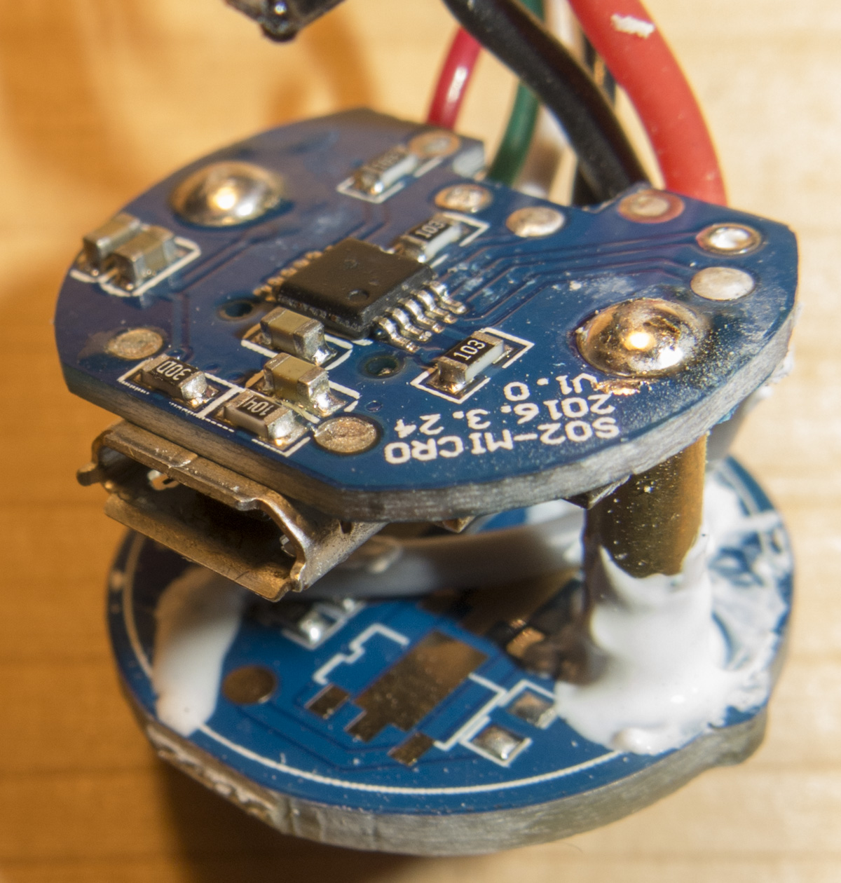
Driver assembly before gluing the old board on top of the TA driver to fix the position USB slave board
I had to cut the USB opening a bit as I trimmed not enough leng of the bolts
The lead connecting the old slave board with the battery, can be easily disconnected
thanks for the review
have you tried using the tailcap from the skilhunt h03? if the threading is the same as all the other astrolux it will match (only thing is, you need to move the oring to the threading groove)
Simple solution to the USB cover problem: I thought I would have to cover it with Gaffer tape, but there is a simpler inbuilt way: just slide the clip around, until its tip is on top of the unruly cover §;) it also gives you the right grip with switch facing you and clip locked in your fingers. - I am not a technical nerd so could someone enlighten me on the reason for the need of an unprotected battery ? - Is it only a question on physical size or will a protected battery damage the flashligt or damage itself ? - I first ordered a Soshine 18350 and it does fit, even being a protected one, - and the light seems to work. I have the recommended: Keeppower 3.7V IMR 18350 750mAh - on its way, should I also expect it to put out more power ? - as it has the very high: Max 15A discharge