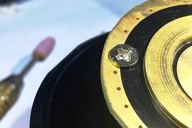
We are in total agreement, the M3 flathead/countersunk screws used in production are absolutely wrong, for several reasons.
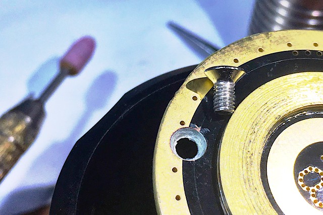
Likewise the holes in the PCB are wrong, I suspect they may have been drilled for M2.5 clearance. Whatever the reason, the screw threads should not bite into them. Apart from just being wrong, you cannot be sure of clamping the PCB against the head if both are threaded. They should be re-drilled to 3mm minimum .
I am simply expressing caution in advising the best way forward at this moment, because for the less experienced it would be better to leave them be for now, until a consensus is reached as to the best replacement, ideally to be supplied as a retrofit kit, for those who want them.
Given the risk of chewing up the heads trying to remove them (cheap screwdrivers, lack of experience in their use, etc, and generally ending up in a muddle …
But be cautious, these type of screw often use a “JIS” cross-head, which is not at-all compatible with any usual Phillips or Pozidriv screwdriver. Really badly incompatible (chews and strips), as anyone who fettles laptops, cameras etc. will know.
JIS screwdrivers are difficult and expensive to source in my experience (paid a lot for mine, from Microtools).
Amazing that you can get a Chinese kit of 300 for $7.60, but generally, you get what you pay for …
That said, this application is non-critical, really they are only there for location purposes. No need to crank them down, just nip them up gently, and in my case then put a dab of weak red locking compound between the head and the PCB.
Another tip: rub the threads on a block of beeswax first before inserting. This lubricates the threads, prevents wear and galling with repeated removal/re-insertion, and also stiffens the screw against loosening.
Mostly the cheapest screws (and threading in the head) are only expected to be assembled once, and never dis-assembled again, for which application they are adequate.
I'm sure someone has answered this, but I couldn't find anything in my scanning of this thread. Is there any problem with boring the driver mounting holes enough to clear the threads and then adding a counter sink for the screw head to fit flat?
I haven't look at the driver pics to determine if the screw holes are the only thru-holes for Batt- connection, but that seems unlikely.
Yep, that is what I'm talking about. Does that cause any problems? It all looks good from here. Plenty of thru-holes and no shorted or broken traces appear evident.
Unless I have missed something, the Batt- connection is entirely through contact between the end of the battery tube and the outer ring on the driver PCB (and all of those vias in it). The need for any contact through the screws or the reverse of the driver and the head is I think a red-herring.
So a DIY fix to countersink the PCB (and maybe a little way into the metal of the head) is a great zero-cost way to improve the mechanical integrity.
But this would not be practical for Thorfire in production. Putting a countersink into the driver PCB as a production step is just not practical.
I am hoping that we can steer Thorfire to do the right thing in future production by using a correct thin pan-head screw, in a correct sized PCB hole.