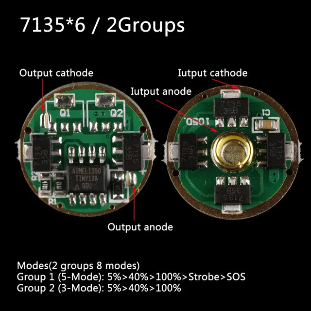
Since Osram LEDs have the anode and the center pad connected together , it is not easy to use them with DTP Boards in a flashlight
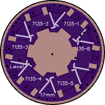
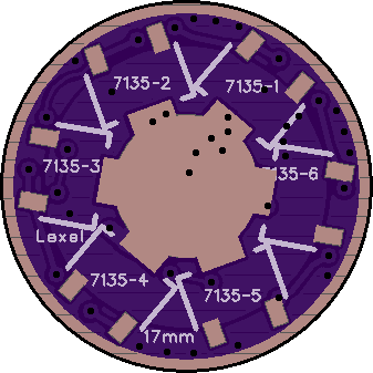
so I though of making a driver for Osram leds where the polarities are reversed , The outer ring of the driver is positive and the center of the driver is negative
(the battery needs to be inserted in the flashlight upside down)
by doing that the body of the flashlight will become postive and that will enable using Direct Thermal path with osram leds
then you can push the led harder and get MORE power while keeping the LED cool
Seems like a great idea. Many handheld laser units are positive to the body. I don't know why flashlights went negative to the body. Maybe it was for safety. Cells seem to all have negative charged cases. If the body is positive and there is a short from the cell case to the flashlight body, the cell will be direct shorted when the switch is clicked on.
Hey, that is really nice, Lexel :sunglasses: , this type of board could make me use the Black Flat again. Is an inverted BLF-A6 driver possible as well?, and if a LFPAK56-FET does not fit, a LFPAK33-FET may? (only if you like doing it of course).
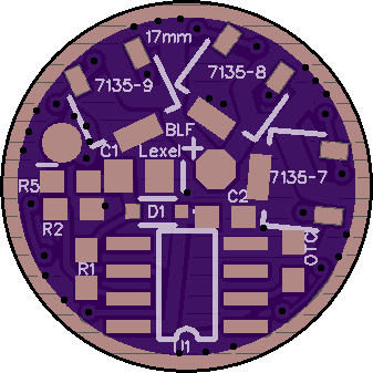
That is very quick Lexel, thanks! Are all 8 7135 chips in parallel or is this a triple channel driver with one 7135 with its own channel? It is relevant because I would like to simply transfer the components (except the FET) of a BLF-A6 driver to this board and make that work directly (I can not do anything related to flashing firmware myself).
Thank you Soooo much Lexel, you saved me alot of time and effort because I was learning to use Eagle in the past 2 days
so far this is my progress :person_facepalming: :cry:
I have many Nanjg 105D Drivers, like this one
Can I install their Components on your Driver ?
if not, Could you share the Needed Components for the Driver Please, or even a Nanjg 105D .sch file would be Greatly Appreciated
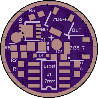
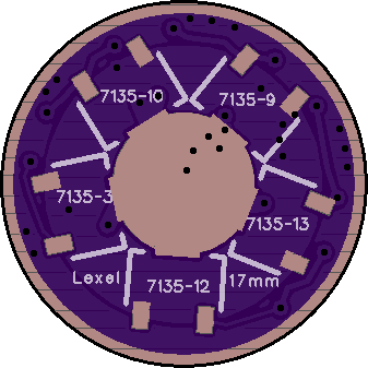
105D driver should work with Tripledown layout, same pin for the 7x AMCs
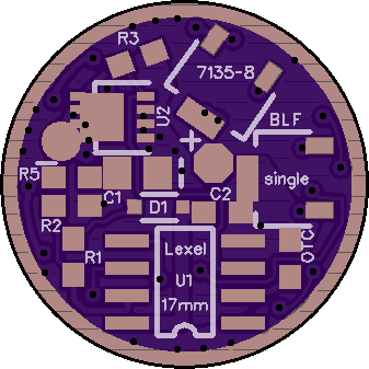
R5, C1 and C2 are to filter voltage spikes from the MCU, at least R5 you have to bridge or equip with 4.7Ohm resistor
That is wonderful Lexel, if built up one-sided I can even use 2 chips and have up to 700mA regulated (mode spacing with A6-firmware should not be too bad)! I ordered 3, will check them out, and report here.
I’m not sure if I’m a rare exception: can solder very well but can’t do computer stuff. For this board I can just rob all components off a common BLF-A6 board (or BLF X5/X6 board) and that is all there is to it.