Only this part is not correct :
2* 4.2V 5000mAh batteries in seires equal to one 8.4V 5000mAh .
Only this part is not correct :
2* 4.2V 5000mAh batteries in seires equal to one 8.4V 5000mAh .
No, it’s correct as far as actual power output.
5,000 8.4v = 10,000 4.2v
Using the lower voltage helps people to better understand and compare the power. This is a detail I left out so as not to confuse people.
Batteries in parallel you can add up the mah, but voltage does not increase.
Batteries is series you add up the voltage, but mah does not increase.
It’s a little complicated for the average person.
I just want to show the overall power differences. Does that make sense?
I understand how you think , but it thought i would mention it if anyone has the emitter as 6V in his mind while reading your post . :+1:
Convoluted, that’s what it is.
There is no 4V equation here. The XP-L’s in the Q8 pull 3.3-3.6V, even though the cells are 4.2V when charged. Similarly, there is no 6V equation in the L6 with XHP-70 or 70.2, since that emitters forward voltage is over 6V, especially when pushed, so if you’re figuring wattage of each light then a more accurate reading of voltage and amperage needs to be taken at the emitters. The Cree datasheet on the 70.2 shows that at 4.8A max current the Vf is between 5.6V and 6.1V, so figuring in 4V just to play easy with the math doesn’t actually equate to what’s going on. In the same way, Giorgo was exactly right in that 2 26650’s in the L6 are an 8.4V 5000mAh battery. Pushing the 70.2 hard with an FET driver has it’s Vf up around 6.8V or more, so there is a 6.8Vf on a falling 8.4V power supply. You can’t divide up the amperage being drawn just to satisfy easy math. 12A at 6.8V (2 parallel 2 series emitters) is 81.6 watts of power being consumed, in the same way that 21A at ~3.6V (4 parallel emitters) is 75.6 watts in an over- driven Q8. Since the 4 cells of the Q8 (all 4 cells together, a battery) are being drawn on in parallel, using 3000mAh cells will indeed give 12,000mAh of power supply, so the battery is running at a 1.75C draw, while in the L6 (at 12A) the 5000mAh battery is seeing a 2.4C draw, obviously falling faster due to the extra hit they’re taking.
Dealing with actual numbers, real time at-the-emitter voltages and amperages, makes it easier to understand where the heat is coming from and why the cells drain so fast. For me, anyway.
And for the record, merely swapping XP-L2’s into a Q8 only nets around 7300 lumens, even with spring bypasses. More needs to be done to get more output. And my Q8 with SST-40’s is making over 11,200 lumens on rested VTC5A cells.
Thanks Dale. I have a tendency to over simplify things to make it easier to understand. I’m like a elementary school teacher and your like a high school teacher. Lol
One of my L6 stopped working. Oddly enough, the one I don't use and keep in the box as new.
I have a few L6's so could swap things around to determine what is going and so far no luck.
1 Tail cap is working
2 Batteries are working
3 battery tube works on other L6's no problem.
4 Head does not work when using on my other L6's
Driver retaining ring tight?
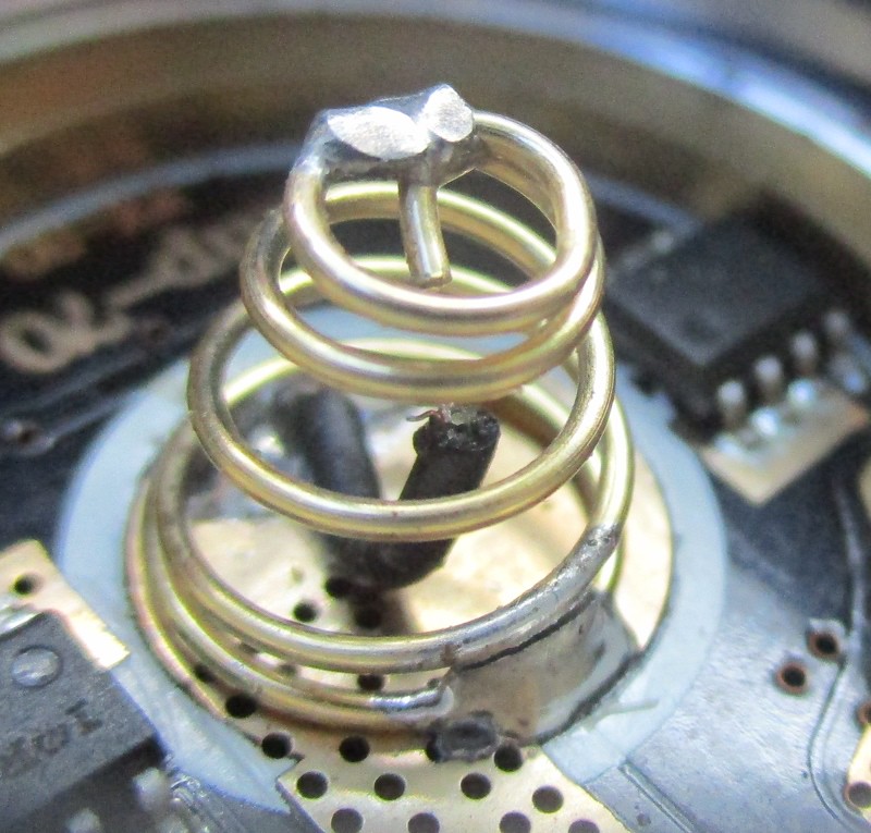
Ring was tight but you were close! Had to get out my magnifying glass and I see the spring bypass wire has dislodged. This is the L6 I posted a long time ago was causing on and off problems, but now we got it.
I'm not the best at soldering, but I'll give it a try. Looks tight in there! Any tips are more than welcome.
It should still work with out the bypass…unless the bypass touched earth (ground)!
Then it might have fried the driver, maybe…
Well, goes to show you how much I know. Maybe the driver is fried or something, but I never smelled anything when I used it in the beginning to test it.
I don't see that the wire touched ground anywhere. It was hanging loose in the middle.
Now that I think about it, wire could have touched ground when the batteries were in and the spring compressed. Are there any tests I can do to determine for sure if the driver is fried?
This usually happens when batteries are too long and the springs bottom out, breaking the bypass, like I said usually. could be a weak solder joint ,who knows?
The IC or Buck is pretty tough, some are, they can take a bit of abuse to a point, depending how long or how HOT is got during the ground short. IF this is what happened? Can you pop the driver out and take a pic of the other side?
Ok, Will give it a try now and pull the driver and post a pic. Might take a little while as this is my first time doing that.
I need to go to the hardware store and get some ring tool as the driver is really tight in their. Will post a pic tonight if I
can get it out.
Well the saving grace is by the looks of your pic, the bypass is still contained within the spring, so lets hope for the best! Not knowing the history of what has been done or tried to the light to get it to work?
It could have popped in and out of the spring during the attempts to get the light working?
It could be just a bad switch wire? I’m looking for the stock driver in the meantime, should have a bunch of them some where? :person_facepalming:
I didn't do much to get it work, just today a few minutes switching battery tubes and tail caps that's all. I also have another driver sitting in my box that I ordered from Simon for the L6 so if all fails, I can try that. Tonight some time I will have it all apart first and see how it all looks. Maybe it is just a bad switch wire in the head.
Cool check your switch wires! I found a couple of the L6 stock drivers. And going by memory and what I see on the stock driver is the Black lead going to the LED is really close to the ground ring. Now if the driver cavity pocket is oversize and the retainer ring is a bit sloppy, IT could be Possible that the Black lead going to the LED might be grounded out and the driver is not seeing the signal? A possibility….
That could explain why sometimes it would work and sometimes not possibly. I never used that particular L6 more than just testing it a few times if it would work. All of a sudden in the past it did and I thought everything was fine. I do remember someone helping me out before as I had the wrong end of the battery tube screwed into the head and they noticed it from the pic I posted.
It also could explain why the driver spring bypass is broken, bottoming out the springs puts force on the driver pcb, could have moved the driver/retaining ring over while twisting everything together. I don’t really know until I have the light in my hands, and I could test it, but I have heard of, done/seen some pretty strange/un-explainable things and shit happens! ![]()
I did some new stuff
I made it possible to run a tail light board for the L6
Best is to use very efficient LEDs to keep the bleeder and tail board parasitic drain low
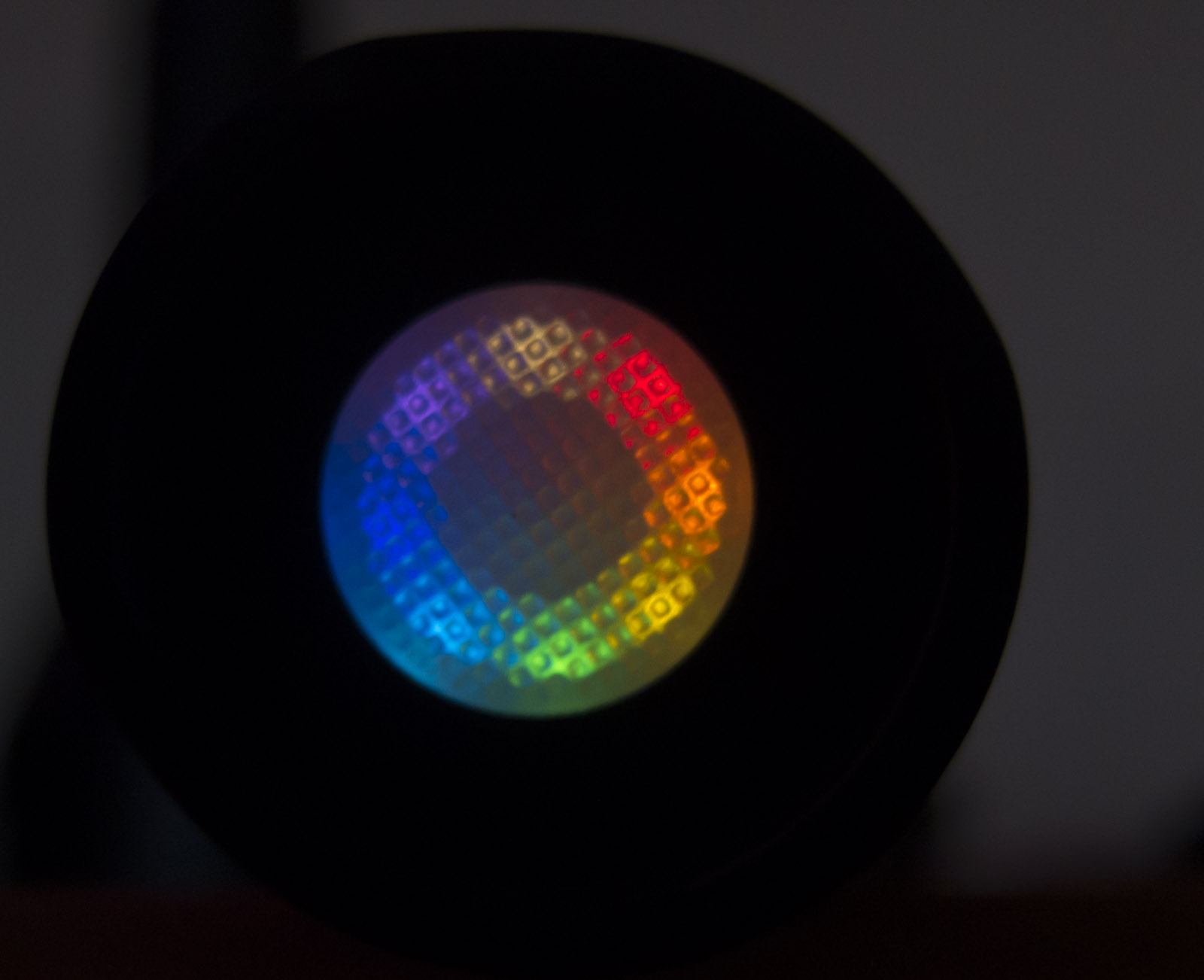
But for the sage Rainbow is also possible
Also side switch LED Board like this available now
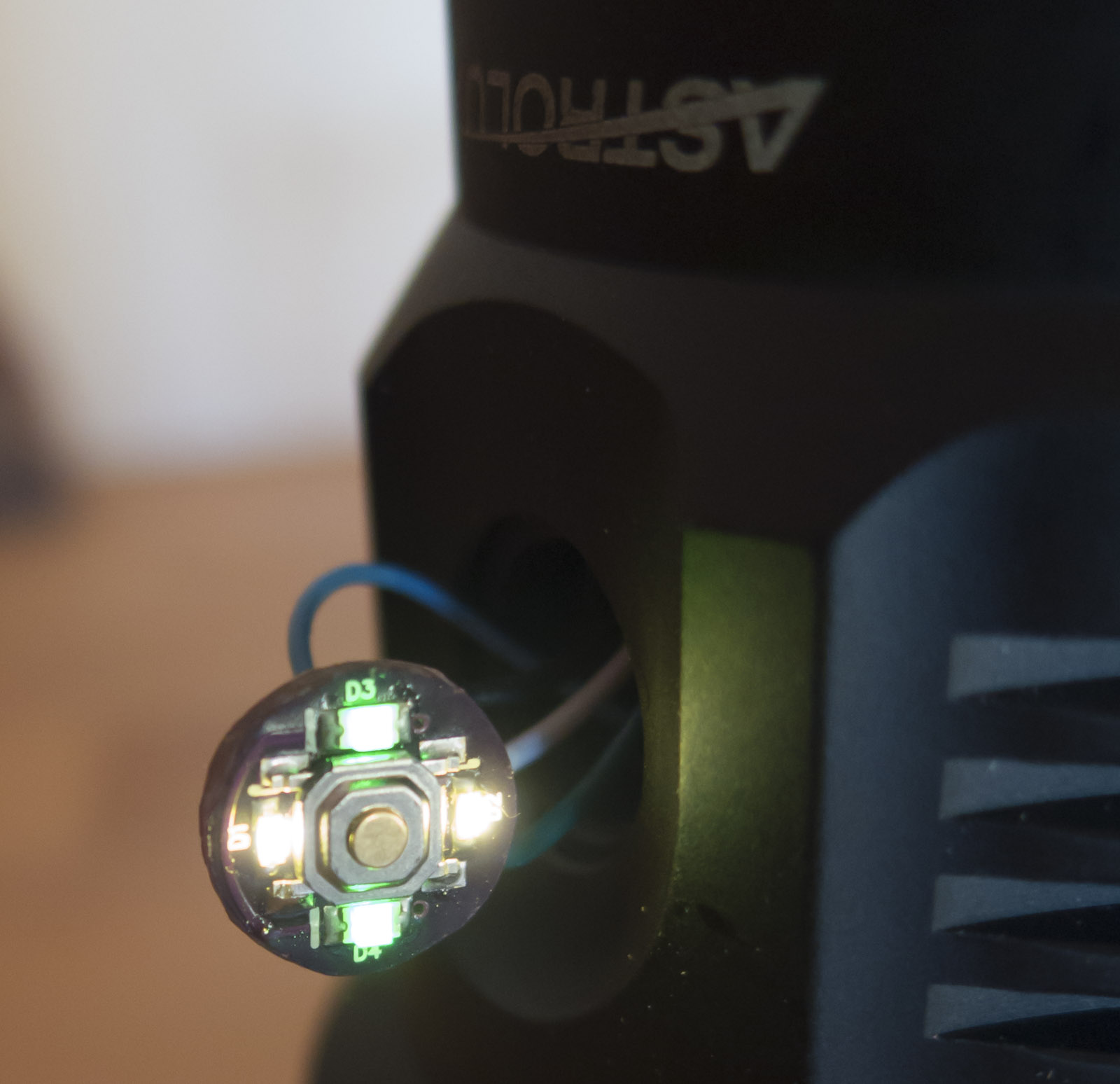
I have 10 colors of LEDs it is possible to mix all kind of them as each LED has its own balance resistor
You got me thinking there so I whipped out my digital calipers and the tail end inner ridge to the end of the threads is 11.50mm and the head end of the tube measures 12mm, so there would not have been any extra pressure on the driver, just a little less and when I insert the batteries with the tube switched, they still protrude the same amount past the tail end.
Very nice Lexel, do you have part numbers yet so we can order?