My USBasp arrived today, so I decided to take my Emisar D1 apart. Worked like a charm. Stupid thing is I’m still waiting for my SOIC8 clip. So I’ll probably order one from Amazon with evening express, cause I caaan’t waaiiiit now. ![]()


That Meteor looks awesome, ah who am I kidding, they all look awesome. ![]()
Today I wrapped 3 30Q’s from NKON with clear wrap (also from NKON), the first time I used the hot air thing for anything, it went easy ![]()
As you can see they are going to live in the ROT66, with the wraps it is a very snug fit, no rattling (was not a problem anyway).
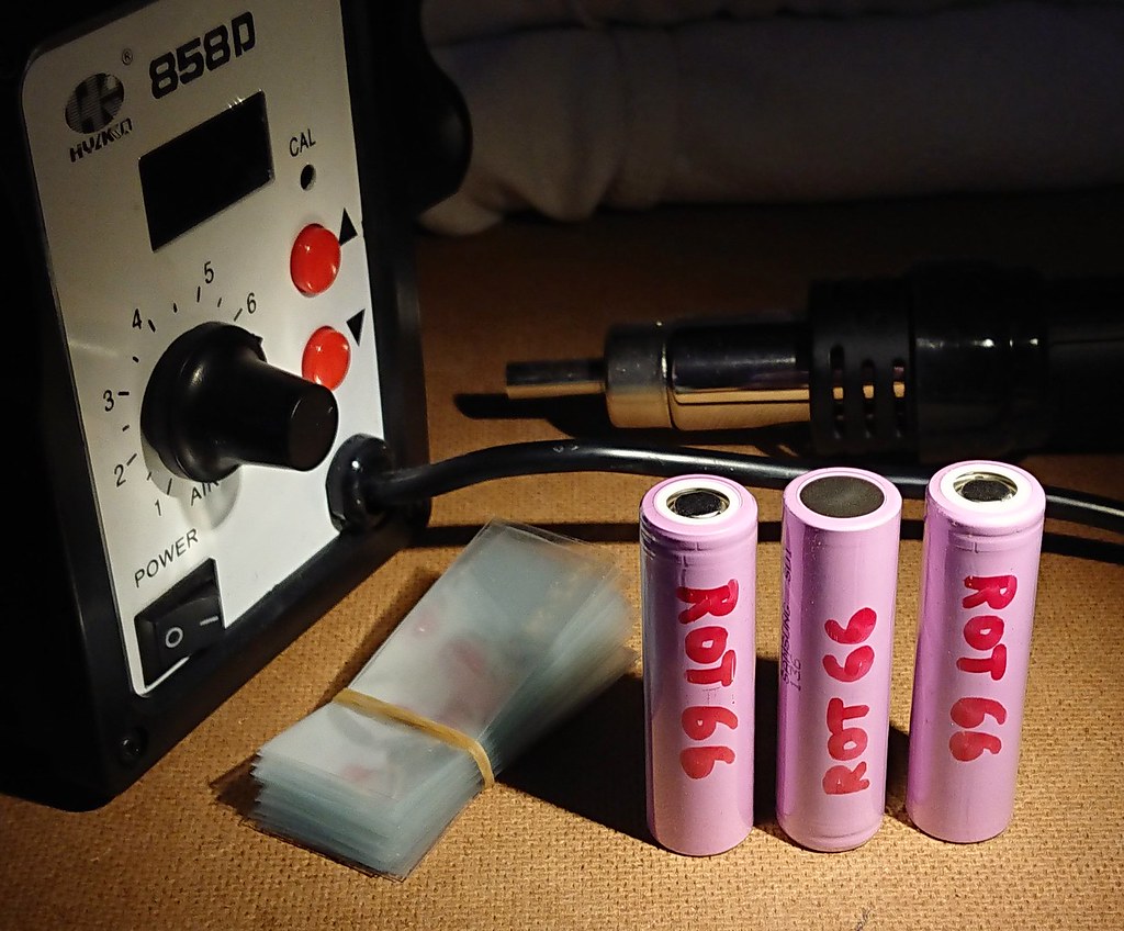
Always a good idea to number the cells and date them, so you can keep track of the characteristics and see if some rotation helps keep em balanced. I also like to write the IR on them from the first charge to be able to see if they are degrading over time and hard use. ![]()
Do you guys typically wrap over the top of the existing wrap or remove and re-wrap?
Good idea, should have done that before the wrapping. Next time I will think of that ![]()
I usually leave the factory wrap on. Almost always fits.
But then, I don’t exactly re-wrap… I cover the writing (mine) with a piece of 2” wide heavy duty packing tape and call it good. Usually works… ![]()
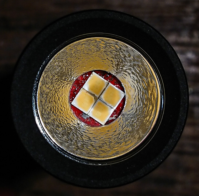
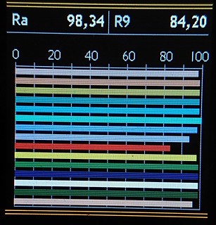
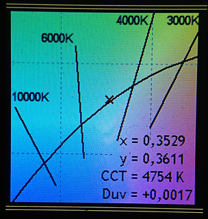
This evening a second Nichia Optisolis mod, same story as my first but now in a Convoy S9, a bit more difficult than the S2+ build but the light will be a present so it needs USB charging. A 16mm XM Noctigon was first sanded to 15mm, bottom made very flat and edges rounded, this was done because it will be glued in later with AA-adhesive and the board must not make electrical contact with the housing. Then a solder-pad to the core of the board was scratched at the side. Then the two original +and - solder pads were connected with a wire. Then four 5000k Optisolis leds were reflowed on the XM-pads, the larger minus pads all facing inwards soldered on the central thermal pad, the smaller plus pads of the leds to the plus and minus pads on the outside.
Lots of re-trying, I had one led reversed it appeared :person_facepalming: , made a dirty job of the board eventually but in the end it worked.
The reflector had to be reamed to 8.5mm diameter, and slightly sanded on the underside afterwards to remove the sharp edge. It fits tightly around the 4-led array and I will not use a centering piece. The board is thicker than the stock board, that will compensate for not using the centerpiece.
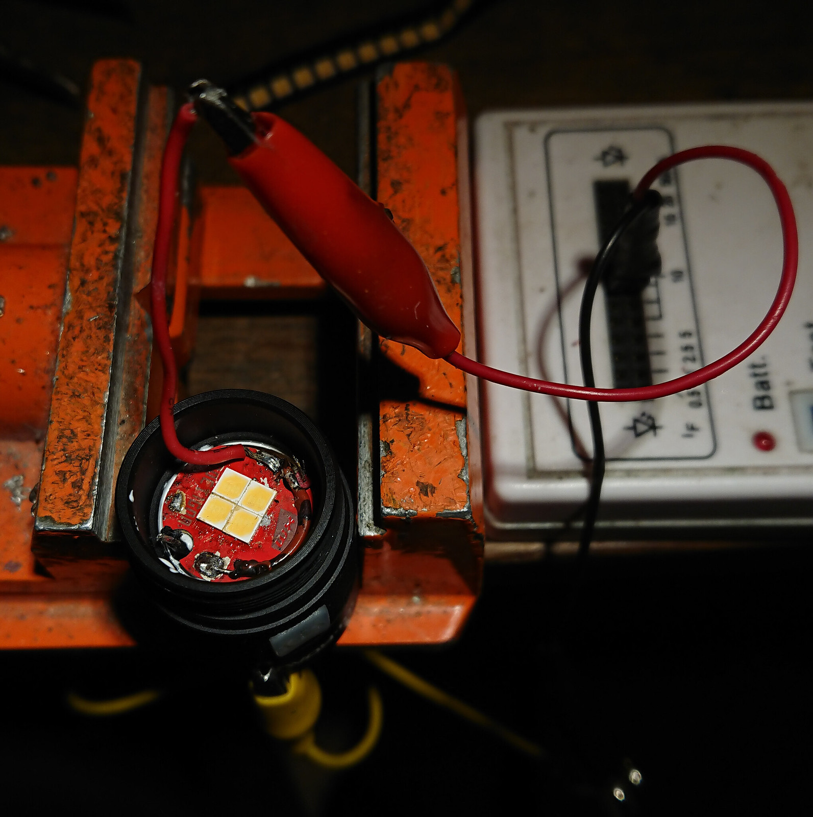
The board was glued in with a led-tester connected to leds+ and head shell, so that a short between board and head would light up the leds, so I would be able during hardening of the glue to wiggle the board to remove the short. But all went well without shorts luckily, not the greatest thermal connection from board to flashlight but the current will be under 2 amps so that should be ok. The temorary plus-wire was removed and led wires soldered to the board.
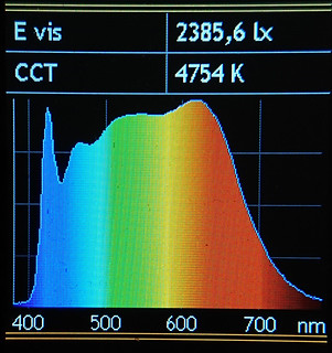
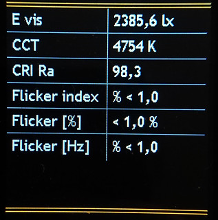
I hoped for about 400 lumen and that is what I got: 390 lumen OTF (on a Keeppower 1200mAh 18350 battery, I made a S9 shorty). So that must be about 500mA per led which is good for a build like this.
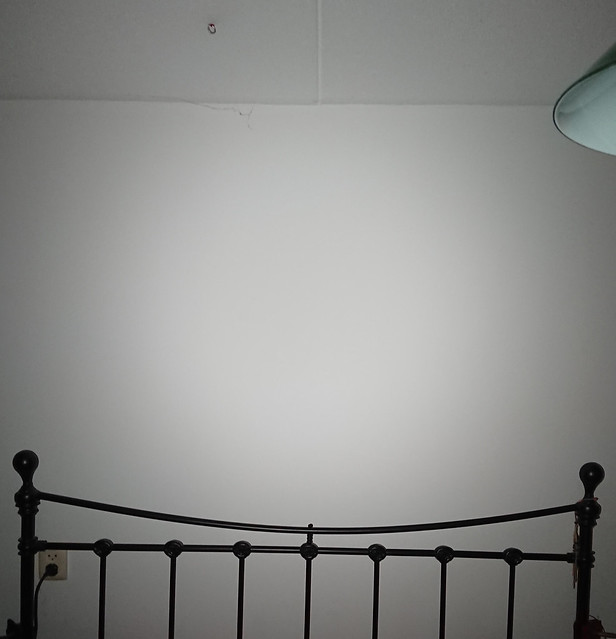
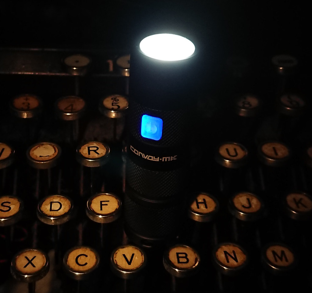
I knew the glass needed heavy frosting but I still checked the beam.
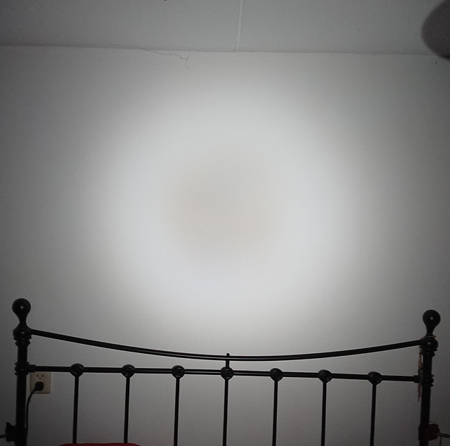
The beam is not really bad actually, but the frosting is needed. Some heavy sanding with 180 grit 3M sandpaper later.
Almost perfect! ![]()
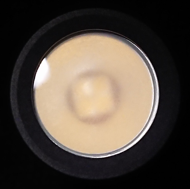
Checking the big smooth center of the beam:
The messy work did not ruin the light quality.
Finished! ![]()
Nice mod djozz. I have no idea where you get the patience from. ![]()
Thanks, I didn’t think to do that. Now I have several sets of 30Q’s, I will do this soon, i still have them separate, but not with their new characteristics. ![]()
That’s really nice Jos, good work! Someone will be extremely pleased with that one! ![]()
Today I built an Eagle eye X6 triple with Osram oslon square 4000K 96 CRI leds and BLF A17DD driver and a copper spacer from kiriba-ru.
Thanks Dale (and Steve) The someone is actually my mother in law, it is her birthday sunday. She is an artistic therapist and does not get good daylight in her studio in the cellar of the house. This is solved by some daylight fluorescent tubes but it comes in handy at times to have some floody instant real daylight to check colours.
Btw, next to my ROT66, this light looks really green. Face it guys, reality is ugly green :party:
Talking about green, which generation Oslon Square were these, and how do you like the tint?
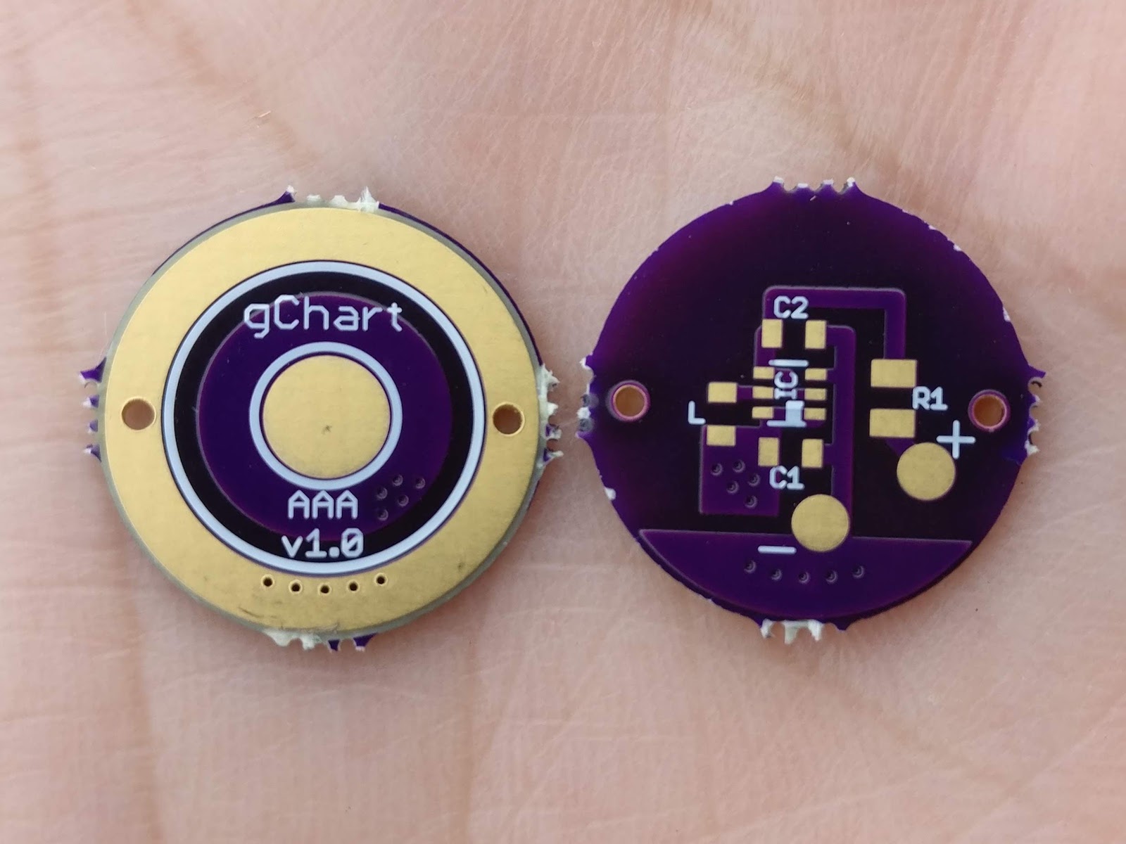
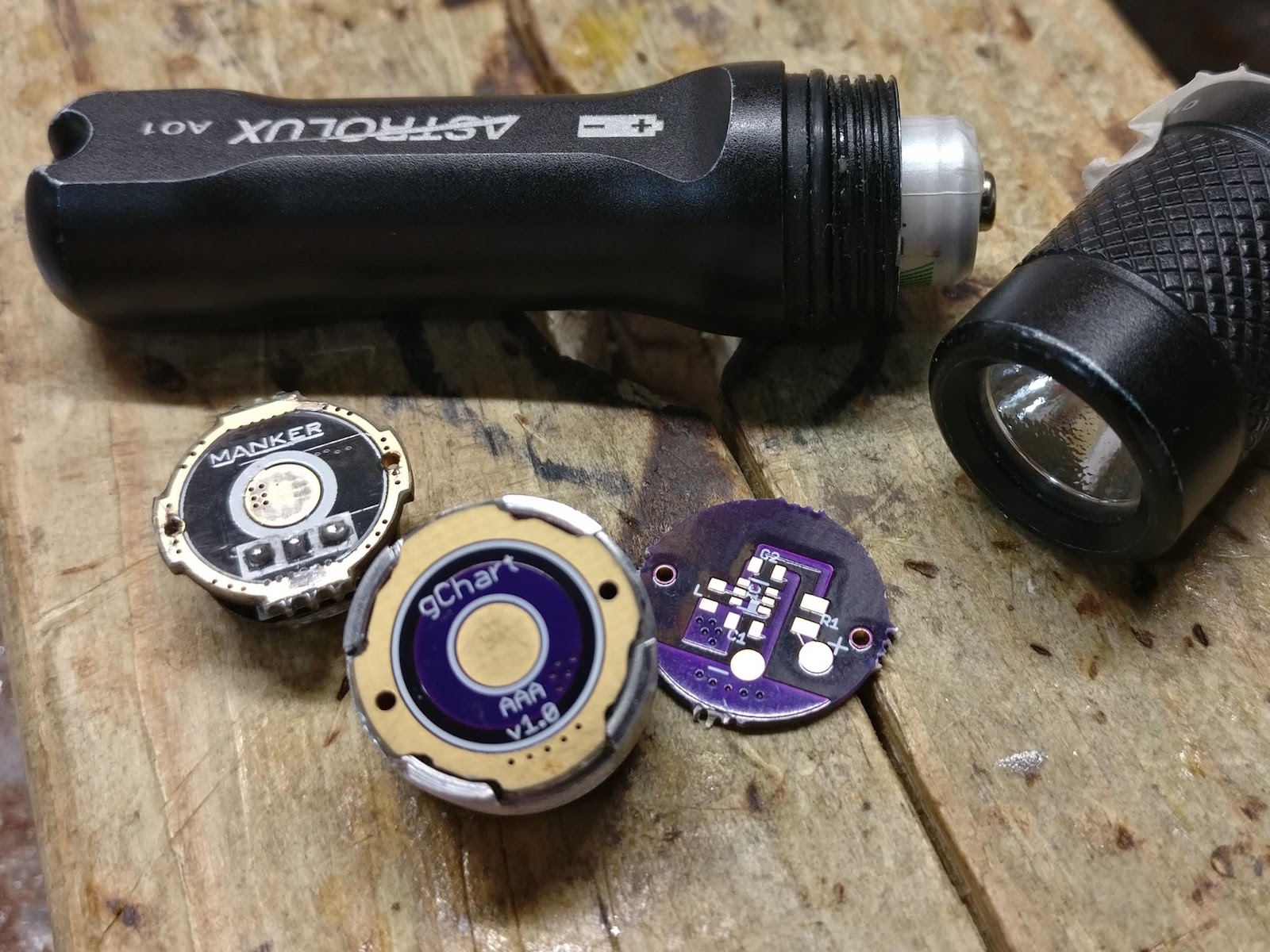
My Astrolux A01 quit working almost 2 years ago, and I had spare parts laying around from the v1.0 of my Booster Tails. So what to do? Create a basic boost driver for it! No MCU, no modes, no PWM… just nice, consistent output. It can technically handle a 10440 as well (input: 0.7 - 5.5 V), but I don’t see a need for that.
My 7yo needed a simple light for reading at night, so I dialed it down to ~6.7mA to the 219B for 3 lumens. I think that may even be too bright.
Nice one gchart! I will have to read into your booster tails, they are nice.
Thanks djozz! And that Convoy S9 Optisolis build looks very cool, good job on that!
I think it is so nice that I’m going to repeat the mod for myself (hopefully making a less dirty board), maybe in 6500K Optisolis leds. Just ordered a new S9 with short tube for that.
Can I be your son for a week or so gchart? ![]()