usually I use coils that I use are at least 3-4 times higher rated than the output current to keep losses low,
you cant use a 5A max rated coil for 5A output
also noticed on your design the input caps are missing, no wonder the inductor has a hard time
same with the capacitors there is a calculation that defines minimum which with like 10uF at 500kHz for 3S—>6V,
you can simply calculate it fromm the offtime C=I*toff(/1000000000 for ns)/1,44****(2 minimum safety value, better x4)
I doubled itat least to be on the safe side,
the more input caps the better for efficiency as the voltage stays higher so we get less current losses
you can trust the tool, the results are almost identical to my LM3409 calculation
the thing is its dynamic switching frequency like most high side sensing resistor buck controllers
no way to modify it besides Inductor selection, this leads you down more or less to measure switching frequancy and then if its not around 300-500kHz change inductor value
I took your values and calculated the fwitching frequency
I get about 800kHz with 4.7uH, which is a bit on the high side
the thing is that switching frequency should be calculated by the tool but its not, very odd
I will try it with a 3.3uH inductor and add input capacitor 3x10uF.
Shall I also add a 10uF capacitor accross the LED terminals? Or is it only optional? No calculation of it in the datasheet.
I also calculated the switching frequency according to the formula that can be found in the manual of the 16820 chip.
According to this, if you increase the inductivity the frequency gets lower.
And if you change the switching frequency in the calculator of maximintegrated the min. inductivity do not change.
I have just had time to build the modified driver.
With the modification you suggested the driver got cooler but it is still hot. Especially the FET. driver
I connected it to an adjustable power supply and measured the followings:
Input 8.4V 4.16A >> 34.9W
LED 6V 5.04A >> 30.24W
So the efficiency is about 86%
I tried out what happens if I use it without cooling (the driver was not attached to any cooling plate, only the led).
The input current increased and when the efficiency decreased to about 83%, the fet got smooking hot and died.
In this case the driver should have dissipated ~6.5W
So I think that my driver less efficient and much hotter than it should be.
And one thing that is also strange, I ajusted the input voltage from 6 to 12 V. i thought that the led current should be constant. But is changed parallel to the input voltage.
I thought that a buck driver provide constant output if the input voltage is bigger than the led voltage.
Which FET do you use, sounds it has way too high switching losses
You need one with low gate charge, usual decent fast N-Mosfets have 4-7mOhms but only about 5-10nC total gate charge
Has this regulator a fixed switsching frequency or do you need to set it with a resistor?
It likely switches way too fast
The only way to see whats going on is using a decent digital memory oscilloscope
There are 2 current sensing resistors on my drawing. Both of them are 43 mOhm. But I use only one of them. They have different sizes, I only have the option to use 1206 or 2512.Only for flexibility… And it is also written on the drawing, 1206 or 2512.
Lexel calculated the equivalant resistance of parallel resistors and he got 21.5 mOhm and from this 9A.
But the current should be only 200mV/43mOhm= 4.6A
But it could go higher and was not constant as I changed the input voltage.
If your output gets higher with more input voltage there is definately something wrong with the switching frequency or current sensing
the buck has to stay stable in output
I also see no 1uF directly connected to the buck input Vcc that is described in the datasheet
with 3.3uH I calculated 200kHz
also the driver design tool points more to 4.7uH
also too low input caps can cause a drop, but not a increase with voltage over the current that the sense resistor should give
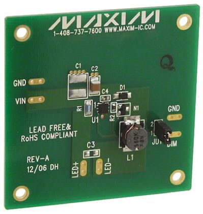
According to the datasheet, C1 and C3 are optional. “Typically, capacitor C1 is not required if the power supply is relatively close to the EV kit. If long wires are used
to connect the power supply to the EV kit, install up to
10µF of bulk capacitance at the surface-mount 2220
pads provided for C1.”
“Typically, the LED ripple current equals the inductor ripple current. To reduce the LED ripple current, install
optional output capacitor C3. The EV kit provides surfacemount 0603 pads for a capacitor nominal value of 0.1µF.”
The input capacitor you did not see, is there. This is C4 1uF capacitor on my schematics.
I recalculated the design with Maximintegrated’s design tool: Design tool
Changing the switching frequeny in the excel sheet does not really influence the L value calculated by it .
And you can also change the input voltage in quite a big range without influencing the L value.
The only new info I got from the eval kit datesheet is:
_To enter hysteretic mode, the following input requirements must be met: set VIN above 5V or above VFLED +
4V (whichever is greater), and provide 1.1A of input current to the EV kit. If low-voltage or low-current input conditions fail to meet the input requirements for hysteretic
mode, the MAX16820 controller operates in linear
mode providing DC current to the LED load._
The excel sheet does not have any warnings about it. According to it the design is feasible.
So I think it means that for a 6V led I need at least 6+4=10V input voltage. Othervise the driver will operates in linear mode. Most probably that is why my output current changed as I changed the input voltage. But if I make a simple calculation: 6V*4,8A=28,8W this is the power consumption of my XHP70. If I increase the input voltage to 10V, the input current would be around 2,8A.
If I increased the output voltage of my power supply over 7,4V (simulating a 2 cell lipo) the current was also increasing until my power supply limited it at around 5A.